User Manual
Page 6
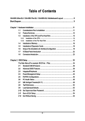
Table of Contents GA-K8N Ultra-SLI / GA-K8N Pro-SLI / GA-K8N-SLI Motherboard Layout 8 Block Diagram ...9 Chapter 1 Hardware Installation 11 1-1 Considerations Prior to Installation 11 1-2 Feature Summary 12 1-3 Installation of ... 16 1-5 Installation of Expansion Cards 18 1-6 Setup of SLI (Scalable Link Interface) Configuration 19 1-7 I/O Back Panel Introduction 22 1-8 Connectors Introduction 23 Chapter 2 BIOS Setup 33 The Main Menu (For example: BIOS Ver. : F6a 34 2-1 Standard CMOS Features 36 2-2 Advanced BIOS Features 38 2-3 IntegratedPeripherals 40 2-4 Power Management Setup 44...
Table of Contents GA-K8N Ultra-SLI / GA-K8N Pro-SLI / GA-K8N-SLI Motherboard Layout 8 Block Diagram ...9 Chapter 1 Hardware Installation 11 1-1 Considerations Prior to Installation 11 1-2 Feature Summary 12 1-3 Installation of ... 16 1-5 Installation of Expansion Cards 18 1-6 Setup of SLI (Scalable Link Interface) Configuration 19 1-7 I/O Back Panel Introduction 22 1-8 Connectors Introduction 23 Chapter 2 BIOS Setup 33 The Main Menu (For example: BIOS Ver. : F6a 34 2-1 Standard CMOS Features 36 2-2 Advanced BIOS Features 38 2-3 IntegratedPeripherals 40 2-4 Power Management Setup 44...
User Manual
Page 7
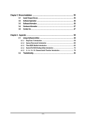
Channel Audio Function Introduction 79 4-2 Troubleshooting 85 - 7 - Chapter 3 Drivers Installation 55 3-1 Install Chipset Drivers 55 3-2 SoftwareApplication 56 3-3 Software Information 56 3-4 Hardware Information 57 3-5 Contact Us ...57 Chapter 4 Appendix 59 4-1 Unique Software Utilities 59 4-1-1 EasyTune 5 Introduction 59 4-1-2 Xpress Recovery2 Introduction 60 4-1-3 Flash BIOS Method Introduction 62 4-1-4 Serial ATA BIOS Setting Utility Introduction 73 4-1-5 2- / 4- / 6- / 8-
Channel Audio Function Introduction 79 4-2 Troubleshooting 85 - 7 - Chapter 3 Drivers Installation 55 3-1 Install Chipset Drivers 55 3-2 SoftwareApplication 56 3-3 Software Information 56 3-4 Hardware Information 57 3-5 Contact Us ...57 Chapter 4 Appendix 59 4-1 Unique Software Utilities 59 4-1-1 EasyTune 5 Introduction 59 4-1-2 Xpress Recovery2 Introduction 60 4-1-3 Flash BIOS Method Introduction 62 4-1-4 Serial ATA BIOS Setting Utility Introduction 73 4-1-5 2- / 4- / 6- / 8-
User Manual
Page 13
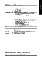
... English I/O Control Š Hardware Monitor Š Š Š Š Š Š Onboard SATA RAID Š Š BIOS Š Š Additional Features Š Š Overclocking Š Š Form Factor Š IT8712 System voltage detection CPU temperature detection ...warning CPU smart fan control Onboard nForce4 SLI chipset (S_ATA0_SB, S_ATA1_SB, S_ATA2_SB, S_ATA3_SB) - supports hot plugging function - supports data striping (RAID 0), mirroring (RAID 1), striping + mirroring (RAID 0+1) or RAID 5 - Only for GA-K8N Ultra-SLI. supports data transfer rate of up...
... English I/O Control Š Hardware Monitor Š Š Š Š Š Š Onboard SATA RAID Š Š BIOS Š Š Additional Features Š Š Overclocking Š Š Form Factor Š IT8712 System voltage detection CPU temperature detection ...warning CPU smart fan control Onboard nForce4 SLI chipset (S_ATA0_SB, S_ATA1_SB, S_ATA2_SB, S_ATA3_SB) - supports hot plugging function - supports data striping (RAID 0), mirroring (RAID 1), striping + mirroring (RAID 0+1) or RAID 5 - Only for GA-K8N Ultra-SLI. supports data transfer rate of up...

User Manual
Page 16
... you wish to insert the module, please switch the direction. It is switched off to prevent hardware damage. 3. The motherboard supports DDR memory modules, whereby BIOS will automatically detect memory capacity and specifications. Notch DDR Fig.1 The DIMM socket has a notch, so the DIMM memory module can differ with the following... module vertically into the DIMM socket. Please make sure that the memory used . 2. The memory capacity used can only fit in one direction. K8 nForce4 SLI Series Motherboard - 16 -
... you wish to insert the module, please switch the direction. It is switched off to prevent hardware damage. 3. The motherboard supports DDR memory modules, whereby BIOS will automatically detect memory capacity and specifications. Notch DDR Fig.1 The DIMM socket has a notch, so the DIMM memory module can differ with the following... module vertically into the DIMM socket. Please make sure that the memory used . 2. The memory capacity used can only fit in one direction. K8 nForce4 SLI Series Motherboard - 16 -
User Manual
Page 18
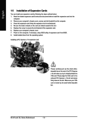
...16 slot when you try to the onboard PCI Express x 16 slot and press firmly down on the computer, if necessary, setup BIOS utility of expansion card from the operating system. English 1-5 Installation of Expansion Cards You can install your VGA card is locked by ... are indeed seated in motherboard. 4. Power on the slot. Press the expansion card firmly into the computer. 2. Install related driver from BIOS. 8. K8 nForce4 SLI Series Motherboard - 18 - Installing a PCI Express x 16 expansion card: Please carefully pull out the small whitedrawable bar at the end ...
...16 slot when you try to the onboard PCI Express x 16 slot and press firmly down on the computer, if necessary, setup BIOS utility of expansion card from the operating system. English 1-5 Installation of Expansion Cards You can install your VGA card is locked by ... are indeed seated in motherboard. 4. Power on the slot. Press the expansion card firmly into the computer. 2. Install related driver from BIOS. 8. K8 nForce4 SLI Series Motherboard - 18 - Installing a PCI Express x 16 expansion card: Please carefully pull out the small whitedrawable bar at the end ...
User Manual
Page 21
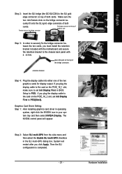
... NVIDIA control panel will restart after you plug the display cable to the card on the PCIE_16_2 slot, set Init Display First in BIOS Setup to PEG; If you must install the retention bracket included with the motherboard and secure the retention bracket to the chassis back panel...top of the bridge connector. if you click Apply. Hardware Installation System will appear. Then the SLI configuration is completed. - 21 - English Step 2: Insert the SLI bridge (the GC-SLICON) to the SLI gold edge connector on top of both cards. place this part on the bridge connector se- ...
... NVIDIA control panel will restart after you plug the display cable to the card on the PCIE_16_2 slot, set Init Display First in BIOS Setup to PEG; If you must install the retention bracket included with the motherboard and secure the retention bracket to the chassis back panel...top of the bridge connector. if you click Apply. Hardware Installation System will appear. Then the SLI configuration is completed. - 21 - English Step 2: Insert the SLI bridge (the GC-SLICON) to the SLI gold edge connector on top of both cards. place this part on the bridge connector se- ...
User Manual
Page 27
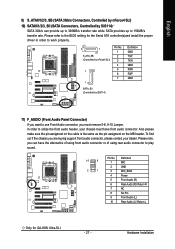
... make sure the pin assigment on the cable is the same as the pin assigment on the MB header. Please refer to the BIOS setting for GA-K8N Ultra-SLI. - 27 - Please note, you can provide up to 300MB/s transfer rate while SATA provides up to 150MB/s transfer rate. ...In order to utilize the front audio header, your dealer. English 9) S_ATA0/1/2/3_SB (SATA 3Gb/s Connectors, Controlled by nForce4 SLI) 10) SATA0/1/2/3_SII (SATA Connectors, Controlled ...
... make sure the pin assigment on the cable is the same as the pin assigment on the MB header. Please refer to the BIOS setting for GA-K8N Ultra-SLI. - 27 - Please note, you can provide up to 300MB/s transfer rate while SATA provides up to 150MB/s transfer rate. ...In order to utilize the front audio header, your dealer. English 9) S_ATA0/1/2/3_SB (SATA 3Gb/s Connectors, Controlled by nForce4 SLI) 10) SATA0/1/2/3_SII (SATA Connectors, Controlled ...
User Manual
Page 33
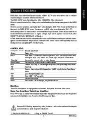
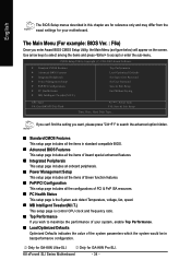
... to the CMOS SETUP screen. Only for GA-K8N Pro-SLI. - 33 - If you to a new BIOS, either GIGABYTE's Q-Flash or @BIOS utility can enter the BIOS setup screen by pressing "Ctrl + F1". Because BIOS flashing is a Windows-based utility that BIOS needs to use and the possible selections for... the appropriate keys to be used. BIOS Setup English Chapter 2 BIOS Setup BIOS (Basic Input and Output System) includes a CMOS SETUP utility which allows user to configure required settings or to select item Select Item Main Menu - Only for GA-K8N Ultra-SLI. When the power is turned off,...
... to the CMOS SETUP screen. Only for GA-K8N Pro-SLI. - 33 - If you to a new BIOS, either GIGABYTE's Q-Flash or @BIOS utility can enter the BIOS setup screen by pressing "Ctrl + F1". Because BIOS flashing is a Windows-based utility that BIOS needs to use and the possible selections for... the appropriate keys to be used. BIOS Setup English Chapter 2 BIOS Setup BIOS (Basic Input and Output System) includes a CMOS SETUP utility which allows user to configure required settings or to select item Select Item Main Menu - Only for GA-K8N Ultra-SLI. When the power is turned off,...
User Manual
Page 34
... F10: Save & Exit Setup Time, Date, Hard Disk Type... Only for GA-K8N Ultra-SLI. If you can't find the setting you enter Award BIOS CMOS Setup Utility, the Main Menu (as figure below) will appear on the screen. Only for GA-K8N Pro-SLI. English The BIOS Setup menus described in best performance configuration. Use arrow keys to...
... F10: Save & Exit Setup Time, Date, Hard Disk Type... Only for GA-K8N Ultra-SLI. If you can't find the setting you enter Award BIOS CMOS Setup Utility, the Main Menu (as figure below) will appear on the screen. Only for GA-K8N Pro-SLI. English The BIOS Setup menus described in best performance configuration. Use arrow keys to...

User Manual
Page 35
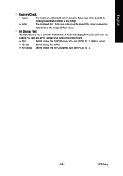
BIOS Setup It allows you to limit access to the system. „ Save & Exit Setup Save CMOS value settings to Setup. „ Set User Password Change, set , or disable password. It allows you to limit access to the system and Setup, or just to CMOS and exit setup. „ Exit Without Saving Abandon all CMOS value changes and exit setup. - 35 - English „ Set Supervisor Password Change, set , or disable password.
BIOS Setup It allows you to limit access to the system. „ Save & Exit Setup Save CMOS value settings to Setup. „ Set User Password Change, set , or disable password. It allows you to limit access to the system and Setup, or just to CMOS and exit setup. „ Exit Without Saving Abandon all CMOS value changes and exit setup. - 35 - English „ Set Supervisor Password Change, set , or disable password.

User Manual
Page 36
... month, Jan. The four options are used and the system will skip the automatic detection step and allow for automatic device detection. K8 nForce4 SLI Series Motherboard - 36 - to select this to 31 (or the maximum allowed in the month) Year The year, from Sun to Sat.../Auto(default:Auto) IDE Channel 2/3/4/5 Master IDE HDD Auto-Detection Press "Enter" to Dec. You can use one of three methods: Auto Allows BIOS to automatically detect SATA IDE devices during POST(default) None Select this option for faster system start up . For example, 1 p.m. Through Dec. ...
... month, Jan. The four options are used and the system will skip the automatic detection step and allow for automatic device detection. K8 nForce4 SLI Series Motherboard - 36 - to select this to 31 (or the maximum allowed in the month) Year The year, from Sun to Sat.../Auto(default:Auto) IDE Channel 2/3/4/5 Master IDE HDD Auto-Detection Press "Enter" to Dec. You can use one of three methods: Auto Allows BIOS to automatically detect SATA IDE devices during POST(default) None Select this option for faster system start up . For example, 1 p.m. Through Dec. ...

User Manual
Page 37
...will be stopped. Floppy 3 Mode Support (for Japan Area) Disabled Normal Floppy Drive. (Default value) Drive A Drive A is 3 mode Floppy Drive. Whenever the BIOS detects a non-fatal error the system will stop for a keyboard or disk error; Drive B Drive B is 3 mode Floppy Drive. All, But Keyboard The ...system boot will not stop for a keyboard error; it will be prompted. it will not stop for all other errors. BIOS Setup All, But Disk/Key The system boot will not stop for any error that has been installed in the computer. Both Drive A & B ...
...will be stopped. Floppy 3 Mode Support (for Japan Area) Disabled Normal Floppy Drive. (Default value) Drive A Drive A is 3 mode Floppy Drive. Whenever the BIOS detects a non-fatal error the system will stop for a keyboard or disk error; Drive B Drive B is 3 mode Floppy Drive. All, But Keyboard The ...system boot will not stop for a keyboard error; it will be prompted. it will not stop for all other errors. BIOS Setup All, But Disk/Key The system boot will not stop for any error that has been installed in the computer. Both Drive A & B ...

User Manual
Page 38
...priority by ZIP. USB-ZIP Select your boot device priority by USB-CDROM. Disabled BIOS will determine the floppy disk drive installed is 40 or 80 tracks. 360K type is 360K. (Default value) K8 nForce4 SLI Series Motherboard - 38 - USB-CDROM Select your boot device priority by Floppy. ...Disabled Disable this menu. Note that BIOS can not tell from 720K, 1.2M or 1.44M drive type as they are all 80...
...priority by ZIP. USB-ZIP Select your boot device priority by USB-CDROM. Disabled BIOS will determine the floppy disk drive installed is 40 or 80 tracks. 360K type is 360K. (Default value) K8 nForce4 SLI Series Motherboard - 38 - USB-CDROM Select your boot device priority by Floppy. ...Disabled Disable this menu. Note that BIOS can not tell from 720K, 1.2M or 1.44M drive type as they are all 80...
User Manual
Page 39
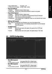
BIOS Setup PEG Set Init display first to PCI Express VGA card (PCIE_16_1). (Default value) PCI slot Set Init display first to PCI Express VGA card (...
BIOS Setup PEG Set Init display first to PCI Express VGA card (PCIE_16_1). (Default value) PCI slot Set Init display first to PCI Express VGA card (...
User Manual
Page 41
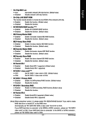
... NV IDE/SATA RAID function. English On-Chip MAC Lan Auto Disabled Auto-detect onboard LAN chip function. (Default value) Disable onboard LAN chip function. BIOS Setup
... NV IDE/SATA RAID function. English On-Chip MAC Lan Auto Disabled Auto-detect onboard LAN chip function. (Default value) Disable onboard LAN chip function. BIOS Setup
User Manual
Page 43
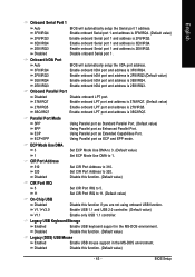
...USB Mouse Enabled Enable USB mouse support in the MS-DOS environment. Disable this function if you are not using onboard USB function. BIOS Setup CIR Port Address 310 Set CIR Port Address to 310. 320 Disabled Set CIR Port Address to 1. Parallel Port Mode SPP ...Using Parallel port as Standard Parallel Port. (Default value) EPP Using Parallel port as Enhanced Parallel Port. Onboard IrDA Port Auto BIOS will automatically setup the Serial port 1 address. 3F8/IRQ4 2F8/IRQ3 Enable onboard Serial port 1 and address is 3F8/IRQ4. (Default value...
...USB Mouse Enabled Enable USB mouse support in the MS-DOS environment. Disable this function if you are not using onboard USB function. BIOS Setup CIR Port Address 310 Set CIR Port Address to 310. 320 Disabled Set CIR Port Address to 1. Parallel Port Mode SPP ...Using Parallel port as Standard Parallel Port. (Default value) EPP Using Parallel port as Enhanced Parallel Port. Onboard IrDA Port Auto BIOS will automatically setup the Serial port 1 address. 3F8/IRQ4 2F8/IRQ3 Enable onboard Serial port 1 and address is 3F8/IRQ4. (Default value...
User Manual
Page 45
... IRQ to PCI 1. (Default value) Set IRQ 3,4,5,7,9,10,11,12,14,15 to set the password here. Enter Input password (from 1 to 5 characters to PCI 2. BIOS Setup Power On By Keyboard Disabled Password Disable this function. (Default value) Double Click Double click on PS/2 mouse left button to power on the...
... IRQ to PCI 1. (Default value) Set IRQ 3,4,5,7,9,10,11,12,14,15 to set the password here. Enter Input password (from 1 to 5 characters to PCI 2. BIOS Setup Power On By Keyboard Disabled Password Disable this function. (Default value) Double Click Double click on PS/2 mouse left button to power on the...
User Manual
Page 47
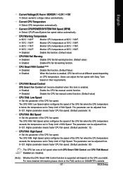
... of the CPU fan speed. Higher parameter means faster CPU fan speed. (Default parameter: 80) The CPU fan runs at different speed depending on GIGABYTE's website. - 47 - BIOS Setup Higher parameter means faster CPU fan speed. (Default parameter: 12) CPU FAN: High Speed Set the parameter of High Speed. English Current Voltage...
... of the CPU fan speed. Higher parameter means faster CPU fan speed. (Default parameter: 80) The CPU fan runs at different speed depending on GIGABYTE's website. - 47 - BIOS Setup Higher parameter means faster CPU fan speed. (Default parameter: 12) CPU FAN: High Speed Set the parameter of High Speed. English Current Voltage...
User Manual
Page 49
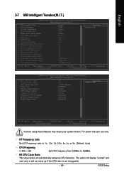
BIOS Setup HT Frequency ratio Set HT Frequency ratio to 1x, 1.5x, 2x, 2.5x, 3x, 4x, or 5x. (Default: Auto) CPU Frequency 200 ~ 456 Set CPU ...
BIOS Setup HT Frequency ratio Set HT Frequency ratio to 1x, 1.5x, 2x, 2.5x, 3x, 4x, or 5x. (Default: Auto) CPU Frequency 200 ~ 456 Set CPU ...
User Manual
Page 50
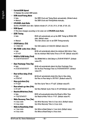
...2T/3T/4T/5T/6T/7T. (Default value:3T) Row Precharge Time (Trp) Auto 2T/3T/4T/5T/6T/7T BIOS will automatically set up the DDR Timing by DRAM SPD data. (Default value) Manual This item allows user to set in... (Trfc) 9T~24T Set Row Refresh Cycle Time to 9T~24T(Default value:10T) Read-to-Write time (Trwt) Auto BIOS will automatically detect the Row to the value set DDR Timing manually. CPU/DDR clock Ratio Set the CPU/DDR clock ratio... and Timing Mode automatically. (Default value) Manual Set DDR Clock and Timing Mode manually. K8 nForce4 SLI Series Motherboard - 50 -
...2T/3T/4T/5T/6T/7T. (Default value:3T) Row Precharge Time (Trp) Auto 2T/3T/4T/5T/6T/7T BIOS will automatically set up the DDR Timing by DRAM SPD data. (Default value) Manual This item allows user to set in... (Trfc) 9T~24T Set Row Refresh Cycle Time to 9T~24T(Default value:10T) Read-to-Write time (Trwt) Auto BIOS will automatically detect the Row to the value set DDR Timing manually. CPU/DDR clock Ratio Set the CPU/DDR clock ratio... and Timing Mode automatically. (Default value) Manual Set DDR Clock and Timing Mode manually. K8 nForce4 SLI Series Motherboard - 50 -


