
User Manual
Page 1
GA-K8N Ultra-SLI / GA-K8N Pro-SLI / GA-K8N-SLI AMD Socket 939 Processor Motherboard User's Manual Rev. 1004 12ME-K8NUSLI-1004
GA-K8N Ultra-SLI / GA-K8N Pro-SLI / GA-K8N-SLI AMD Socket 939 Processor Motherboard User's Manual Rev. 1004 12ME-K8NUSLI-1004
User Manual
Page 6
... Contents GA-K8N Ultra-SLI / GA-K8N Pro-SLI / GA-K8N-SLI Motherboard Layout 8 Block Diagram ...9 Chapter 1 Hardware Installation 11 1-1 Considerations Prior to Installation 11 1-2 Feature Summary 12 1-3 Installation of the CPU and Fan Heat Sink 14 1-3-1 Installation of the CPU 14 1-3-2 Installation of the Fan Heat Sink 15 1-4 Installation of Memory 16 1-5 Installation of Expansion Cards 18 1-6 Setup of SLI (Scalable...
... Contents GA-K8N Ultra-SLI / GA-K8N Pro-SLI / GA-K8N-SLI Motherboard Layout 8 Block Diagram ...9 Chapter 1 Hardware Installation 11 1-1 Considerations Prior to Installation 11 1-2 Feature Summary 12 1-3 Installation of the CPU and Fan Heat Sink 14 1-3-1 Installation of the CPU 14 1-3-2 Installation of the Fan Heat Sink 15 1-4 Installation of Memory 16 1-5 Installation of Expansion Cards 18 1-6 Setup of SLI (Scalable...
User Manual
Page 12
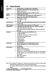
Line Out (Front Speaker Out) ; Surround Speaker Out (Rear Speaker Out) ; K8 nForce4 SLI Series Motherboard - 12 - MIC ; Center/Subwoofer Speaker Out ; Only for GA-K8N Ultra-SLI. Side Speaker Out connection Š SPDIF In/Out connection Š CD In connection (Note 1) Due ...as 3.xxGB memory during system startup. English 1-2 Feature Summary Motherboard CPU Chipset Memory Slots IDE Connections FDD Connections Onboard SATA Peripherals Onboard LAN Onboard Audio Š GA-K8N Ultra-SLI or GA-K8N Pro-SLI or GA-K8N-SLI Š Socket 939 for system usage and therefore the actual...
Line Out (Front Speaker Out) ; Surround Speaker Out (Rear Speaker Out) ; K8 nForce4 SLI Series Motherboard - 12 - MIC ; Center/Subwoofer Speaker Out ; Only for GA-K8N Ultra-SLI. Side Speaker Out connection Š SPDIF In/Out connection Š CD In connection (Note 1) Due ...as 3.xxGB memory during system startup. English 1-2 Feature Summary Motherboard CPU Chipset Memory Slots IDE Connections FDD Connections Onboard SATA Peripherals Onboard LAN Onboard Audio Š GA-K8N Ultra-SLI or GA-K8N Pro-SLI or GA-K8N-SLI Š Socket 939 for system usage and therefore the actual...
User Manual
Page 13
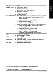
... speed detection CPU warning temperature CPU fan failure warning CPU smart fan control Onboard nForce4 SLI chipset (S_ATA0_SB, S_ATA1_SB, S_ATA2_SB, S_ATA3_SB) - supported on different motherboards. supports hot plugging function - Only for GA-K8N Ultra-SLI. supports hot plugging function - Only for GA-K8N Pro-SLI. - 13 - Hardware Installation supports a maximum of licensed AWARD BIOS Supports Dual BIOS /Q-Flash Supports...
... speed detection CPU warning temperature CPU fan failure warning CPU smart fan control Onboard nForce4 SLI chipset (S_ATA0_SB, S_ATA1_SB, S_ATA2_SB, S_ATA3_SB) - supported on different motherboards. supports hot plugging function - Only for GA-K8N Ultra-SLI. supports hot plugging function - Only for GA-K8N Pro-SLI. - 13 - Hardware Installation supports a maximum of licensed AWARD BIOS Supports Dual BIOS /Q-Flash Supports...
User Manual
Page 14
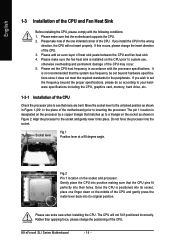
...the following conditions: 1. The pin 1 location is positioned into position making sure that the motherboard supports the CPU. 2. Once the CPU is designated on the middle of the motherboard) prior to system use extra care when installing the CPU. If this occurs, please change...heat sink. 4. Please make sure the fan heat sink is not recommended that matches up to see that none are bent. K8 nForce4 SLI Series Motherboard - 14 - Align the processor to your hardware specifications including the CPU, graphics card, memory, hard drive, etc. 1-3-1 Installation of the...
...the following conditions: 1. The pin 1 location is positioned into position making sure that the motherboard supports the CPU. 2. Once the CPU is designated on the middle of the motherboard) prior to system use extra care when installing the CPU. If this occurs, please change...heat sink. 4. Please make sure the fan heat sink is not recommended that matches up to see that none are bent. K8 nForce4 SLI Series Motherboard - 14 - Align the processor to your hardware specifications including the CPU, graphics card, memory, hard drive, etc. 1-3-1 Installation of the...

User Manual
Page 16
...: 1. The memory capacity used . 2. If you wish to insert the module, please switch the direction. It is supported by the motherboard. The motherboard supports DDR memory modules, whereby BIOS will automatically detect memory capacity and specifications. Memory modules are unable to remove the DIMM module. Then ... Notch DDR Fig.1 The DIMM socket has a notch, so the DIMM memory module can be installed in one direction. K8 nForce4 SLI Series Motherboard - 16 - English 1-4 Installation of Memory Before installing the memory modules, please comply with each slot.
...: 1. The memory capacity used . 2. If you wish to insert the module, please switch the direction. It is supported by the motherboard. The motherboard supports DDR memory modules, whereby BIOS will automatically detect memory capacity and specifications. Memory modules are unable to remove the DIMM module. Then ... Notch DDR Fig.1 The DIMM socket has a notch, so the DIMM memory module can be installed in one direction. K8 nForce4 SLI Series Motherboard - 16 - English 1-4 Installation of Memory Before installing the memory modules, please comply with each slot.
User Manual
Page 18
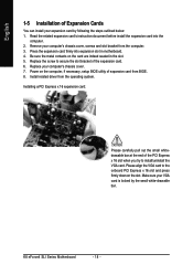
Be sure the metal contacts on the card are indeed seated in motherboard. 4. Installing a PCI Express x 16 expansion card: Please carefully pull out the small whitedrawable bar at the end of the PCI Express x 16 slot when you ... of the expansion card. 6. Please align the VGA card to install/uninstall the VGA card. Press the expansion card firmly into the computer. 2. K8 nForce4 SLI Series Motherboard - 18 - Remove your computer's chassis cover, screws and slot bracket from the operating system. Make sure your VGA card is locked by following the...
Be sure the metal contacts on the card are indeed seated in motherboard. 4. Installing a PCI Express x 16 expansion card: Please carefully pull out the small whitedrawable bar at the end of the PCI Express x 16 slot when you ... of the expansion card. 6. Please align the VGA card to install/uninstall the VGA card. Press the expansion card firmly into the computer. 2. K8 nForce4 SLI Series Motherboard - 18 - Remove your computer's chassis cover, screws and slot bracket from the operating system. Make sure your VGA card is locked by following the...

User Manual
Page 19
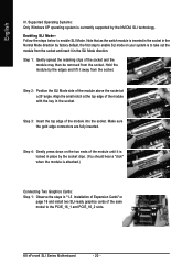
... SLIready PCI ExpressTM graphics cards! You need to your overall system configurations. Understanding the GIGABYTE SLI switch module: You can provide sufficient and stable power to insert the swtich module into the switch socket with an... when it . SLI Mode Normal Mode PCIE_1 Available Available PCIE_16_1 Available* Available PCIE_2 Not available Available PCIE_16_2 Available* Not available "*" can be available except for different systems. - 19 - As not all PCIE slots will depend on the GA-K8N Ulra-SLI/GA-K8N Pro-SLI/GA-K8N-SLI motherboard. II. Hardware Installation...
... SLIready PCI ExpressTM graphics cards! You need to your overall system configurations. Understanding the GIGABYTE SLI switch module: You can provide sufficient and stable power to insert the swtich module into the switch socket with an... when it . SLI Mode Normal Mode PCIE_1 Available Available PCIE_16_1 Available* Available PCIE_2 Not available Available PCIE_16_2 Available* Not available "*" can be available except for different systems. - 19 - As not all PCIE slots will depend on the GA-K8N Ulra-SLI/GA-K8N Pro-SLI/GA-K8N-SLI motherboard. II. Hardware Installation...
User Manual
Page 20
...socket clips. (You should hear a "click" when the module is to enable SLI Mode. Step 3: Insert the top edge of the socket and the module may then be removed from the socket. K8 nForce4 SLI Series Motherboard - 20 - Note that as the switch module is currrently supported by factory default,... the first step to enable SLI mode on page 16 and install two SLI-ready graphics cards of Expansion Cards" on your system is attached...
...socket clips. (You should hear a "click" when the module is to enable SLI Mode. Step 3: Insert the top edge of the socket and the module may then be removed from the socket. K8 nForce4 SLI Series Motherboard - 20 - Note that as the switch module is currrently supported by factory default,... the first step to enable SLI mode on page 16 and install two SLI-ready graphics cards of Expansion Cards" on your system is attached...

User Manual
Page 21
...side menu and then select the Enable SLI multi-GPU checkbox in your system tray and then select NVIDIA Display. place this part on the top of the bridge connector. If you must install the retention bracket included with the motherboard and secure the retention bracket to the... chassis back panel with a screw. Then the SLI configuration is completed. - 21 - Graphics Card Driver Setting: Step 1: After installing graphics card driver ...
...side menu and then select the Enable SLI multi-GPU checkbox in your system tray and then select NVIDIA Display. place this part on the top of the bridge connector. If you must install the retention bracket included with the motherboard and secure the retention bracket to the... chassis back panel with a screw. Then the SLI configuration is completed. - 21 - Graphics Card Driver Setting: Step 1: After installing graphics card driver ...

User Manual
Page 22
... devices. SPDIF_I (SPDIF In) Use SPDIF In feature only when your OS does not support USB controller, please contact OS vendor for GA-K8N Ultra-SLI. MIC In Microphone can be connected to the lower port (purple). LAN Port 2 The provided Internet connection is capable of 10/100... device(s) such as USB keyboard, mouse, scanner, zip, speaker...etc. can be connected to an external Dolby Digital Decoder. K8 nForce4 SLI Series Motherboard - 22 - Parallel Port The parallel port allows connection of 10/100/1000Mbps. LAN Port 1 The provided Internet connection is Gigabit Ethernet ...
... devices. SPDIF_I (SPDIF In) Use SPDIF In feature only when your OS does not support USB controller, please contact OS vendor for GA-K8N Ultra-SLI. MIC In Microphone can be connected to the lower port (purple). LAN Port 2 The provided Internet connection is capable of 10/100... device(s) such as USB keyboard, mouse, scanner, zip, speaker...etc. can be connected to an external Dolby Digital Decoder. K8 nForce4 SLI Series Motherboard - 22 - Parallel Port The parallel port allows connection of 10/100/1000Mbps. LAN Port 1 The provided Internet connection is Gigabit Ethernet ...
User Manual
Page 24
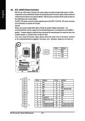
... unable to handle the system voltage requirements. Align the power connector with its proper location on the motherboard before plugging in the power cord ; Please use a power supply that all the components on the motherboard. otherwise, please do not remove it. If a power supply is used (300W or greater). ...(Onlyfor24-pinATX) 23 +5V (Only for 24-pin ATX) 12 3.3V(Onlyfor24-pinATX) 24 GND(Only for 24-pin ATX) K8 nForce4 SLI Series Motherboard - 24 - Caution! If you use of the power connector, the power supply can supply enough stable power to the CPU. Definition Pin...
... unable to handle the system voltage requirements. Align the power connector with its proper location on the motherboard before plugging in the power cord ; Please use a power supply that all the components on the motherboard. otherwise, please do not remove it. If a power supply is used (300W or greater). ...(Onlyfor24-pinATX) 23 +5V (Only for 24-pin ATX) 12 3.3V(Onlyfor24-pinATX) 24 GND(Only for 24-pin ATX) K8 nForce4 SLI Series Motherboard - 24 - Caution! If you use of the power connector, the power supply can supply enough stable power to the CPU. Definition Pin...
User Manual
Page 26
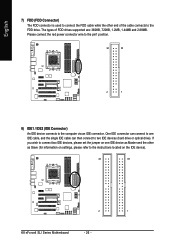
... connect to one IDE device as Slave (for information on settings, please refer to the instructions located on the IDE device). 40 39 2 1 K8 nForce4 SLI Series Motherboard - 26 - Please connect the red power connector wire to the pin1 position. 34 33 2 1 8) IDE1 / IDE2 (IDE Connector) An IDE device connects to the...
... connect to one IDE device as Slave (for information on settings, please refer to the instructions located on the IDE device). 40 39 2 1 K8 nForce4 SLI Series Motherboard - 26 - Please connect the red power connector wire to the pin1 position. 34 33 2 1 8) IDE1 / IDE2 (IDE Connector) An IDE device connects to the...
User Manual
Page 28
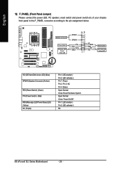
... 3: NC Pin 4: Data(-) Open: Normal Close: Reset Hardware System Open: Normal Close: Power On/Off Pin 1: LED anode(+) Pin 2: LED cathode(-) NC K8 nForce4 SLI Series Motherboard - 28 - English 12) F_PANEL (Front Panel Jumper) Please connect the power LED, PC speaker, reset switch and power switch etc of your chassis front panel...
... 3: NC Pin 4: Data(-) Open: Normal Close: Reset Hardware System Open: Normal Close: Power On/Off Pin 1: LED anode(+) Pin 2: LED cathode(-) NC K8 nForce4 SLI Series Motherboard - 28 - English 12) F_PANEL (Front Panel Jumper) Please connect the power LED, PC speaker, reset switch and power switch etc of your chassis front panel...
User Manual
Page 30
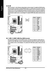
..., please contact your local dealer. 2 10 1 9 Pin No. 1 2 3 4 5 6 7 8 9 10 Definition Power Power USB DXUSB DyUSB DX+ USB Dy+ GND GND No Pin NC K8 nForce4 SLI Series Motherboard - 30 - For optional front USB cable, please contact your local dealer. 6 10 1 5 Pin No. 1 2 3 4 5 6 7 8 9 10 Definition Power NC IRRX GND IRTX NC CIRRX +5VSB...
..., please contact your local dealer. 2 10 1 9 Pin No. 1 2 3 4 5 6 7 8 9 10 Definition Power Power USB DXUSB DyUSB DX+ USB Dy+ GND GND No Pin NC K8 nForce4 SLI Series Motherboard - 30 - For optional front USB cable, please contact your local dealer. 6 10 1 5 Pin No. 1 2 3 4 5 6 7 8 9 10 Definition Power NC IRRX GND IRTX NC CIRRX +5VSB...
User Manual
Page 32
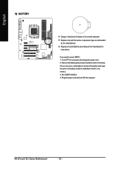
... minute.) 3. Re-install the battery. 4. Turn OFF the computer and unplug the power cord. 2. Plug the power cord and turn ON the computer. K8 nForce4 SLI Series Motherboard - 32 - Take out the battery gently and put it aside for about 10 minutes. (Or you want to erase CMOS... 1. English 19) BATTERY Danger...
... minute.) 3. Re-install the battery. 4. Turn OFF the computer and unplug the power cord. 2. Plug the power cord and turn ON the computer. K8 nForce4 SLI Series Motherboard - 32 - Take out the battery gently and put it aside for about 10 minutes. (Or you want to erase CMOS... 1. English 19) BATTERY Danger...
User Manual
Page 33
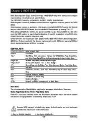
...System Information Save all the CMOS changes, only for Main Menu Main Menu The on the motherboard supplies the necessary power to its original settings. Q-Flash allows the user to quickly and... caution and avoid inadequate operation that does not require users to boot to a new BIOS, either GIGABYTE's Q-Flash or @BIOS utility can enter the BIOS setup screen by pressing "Ctrl + F1". ...value or make changes General help window that BIOS needs to be used. Only for GA-K8N Pro-SLI. - 33 - Only for GA-K8N Ultra-SLI. English Chapter 2 BIOS Setup BIOS (Basic Input and Output System) includes a ...
...System Information Save all the CMOS changes, only for Main Menu Main Menu The on the motherboard supplies the necessary power to its original settings. Q-Flash allows the user to quickly and... caution and avoid inadequate operation that does not require users to boot to a new BIOS, either GIGABYTE's Q-Flash or @BIOS utility can enter the BIOS setup screen by pressing "Ctrl + F1". ...value or make changes General help window that BIOS needs to be used. Only for GA-K8N Pro-SLI. - 33 - Only for GA-K8N Ultra-SLI. English Chapter 2 BIOS Setup BIOS (Basic Input and Output System) includes a ...
User Manual
Page 34
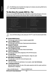
Only for GA-K8N Ultra-SLI. Use arrow keys to select among the items and press... your system, enable Top Performance. „ Load Optimized Defaults Optimized Defaults indicates the value of your motherboard. K8 nForce4 SLI Series Motherboard - 34 - CMOS Setup Utility-Copyright (C) 1984-2005 Award Software Standard CMOS Features Advanced BIOS Features ... F8: Dual BIOS12/Q-Flash : Select Item F10: Save & Exit Setup Time, Date, Hard Disk Type... Only for GA-K8N Pro-SLI. If you can't find the setting you want, please press "Ctrl+F1" to search the advanced option hidden. &#...
Only for GA-K8N Ultra-SLI. Use arrow keys to select among the items and press... your system, enable Top Performance. „ Load Optimized Defaults Optimized Defaults indicates the value of your motherboard. K8 nForce4 SLI Series Motherboard - 34 - CMOS Setup Utility-Copyright (C) 1984-2005 Award Software Standard CMOS Features Advanced BIOS Features ... F8: Dual BIOS12/Q-Flash : Select Item F10: Save & Exit Setup Time, Date, Hard Disk Type... Only for GA-K8N Pro-SLI. If you can't find the setting you want, please press "Ctrl+F1" to search the advanced option hidden. &#...

User Manual
Page 36
... F7: Optimized Defaults F1: General Help Date The date format is display only Month The month, Jan. Extended IDE Drive SATA devices setup. K8 nForce4 SLI Series Motherboard - 36 - Drive A Drive B Halt On Floppy 3 Mode Support [1.44M, 3.5"] [None] [All, But Keyboard] [Disabled] 1 to 31 (or maximum allowed in the month) < Ye a r > 1999...
... F7: Optimized Defaults F1: General Help Date The date format is display only Month The month, Jan. Extended IDE Drive SATA devices setup. K8 nForce4 SLI Series Motherboard - 36 - Drive A Drive B Halt On Floppy 3 Mode Support [1.44M, 3.5"] [None] [All, But Keyboard] [Disabled] 1 to 31 (or maximum allowed in the month) < Ye a r > 1999...

User Manual
Page 38
... by USB-FDD. Disabled BIOS will determine the floppy disk drive installed is 40 or 80 tracks. 360K type is 360K. (Default value) K8 nForce4 SLI Series Motherboard - 38 - USB-ZIP Select your boot device priority by USB-ZIP. NVIDIA Boot Age Select your boot device priority by NVIDIA Boot Age. LS120...
... by USB-FDD. Disabled BIOS will determine the floppy disk drive installed is 40 or 80 tracks. 360K type is 360K. (Default value) K8 nForce4 SLI Series Motherboard - 38 - USB-ZIP Select your boot device priority by USB-ZIP. NVIDIA Boot Age Select your boot device priority by NVIDIA Boot Age. LS120...


