User Manual
Page 12
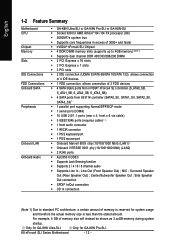
Center/Subwoofer Speaker Out ; K8 nForce4 SLI Series Motherboard - 12 - MIC ; Only for GA-K8N Ultra-SLI. Side Speaker Out connection Š SPDIF In/Out connection Š CD In connection (Note 1) Due to 4GB memory) (Note 1) Š Supports ...Onboard SATA Peripherals Onboard LAN Onboard Audio Š GA-K8N Ultra-SLI or GA-K8N Pro-SLI or GA-K8N-SLI Š Socket 939 for AMD AthlonTM 64 / 64 FX processor (K8) Š 2000MT/s system bus Š Supports core frequencies in excess of 3000+ and faster Š nVIDIA® nForce4 SLI Chipset Š 4 DDR DIMM memory slots (...
Center/Subwoofer Speaker Out ; K8 nForce4 SLI Series Motherboard - 12 - MIC ; Only for GA-K8N Ultra-SLI. Side Speaker Out connection Š SPDIF In/Out connection Š CD In connection (Note 1) Due to 4GB memory) (Note 1) Š Supports ...Onboard SATA Peripherals Onboard LAN Onboard Audio Š GA-K8N Ultra-SLI or GA-K8N Pro-SLI or GA-K8N-SLI Š Socket 939 for AMD AthlonTM 64 / 64 FX processor (K8) Š 2000MT/s system bus Š Supports core frequencies in excess of 3000+ and faster Š nVIDIA® nForce4 SLI Chipset Š 4 DDR DIMM memory slots (...
User Manual
Page 13
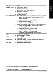
...detection CPU temperature detection CPU / System / Power fan speed detection CPU warning temperature CPU fan failure warning CPU smart fan control Onboard nForce4 SLI chipset (S_ATA0_SB, S_ATA1_SB, S_ATA2_SB, S_ATA3_SB) - supported on different motherboards. supports data striping (RAID 0), mirroring (RAID 1), or ...Win 2003/2000/XP operating systems Use of up to 300 MB/s - supports data transfer rate of 4 SATA connections - Only for GA-K8N Pro-SLI. - 13 - Hardware Installation supports data striping (RAID 0), mirroring (RAID 1), striping + mirroring (RAID 0+1) or RAID 5 - supports...
...detection CPU temperature detection CPU / System / Power fan speed detection CPU warning temperature CPU fan failure warning CPU smart fan control Onboard nForce4 SLI chipset (S_ATA0_SB, S_ATA1_SB, S_ATA2_SB, S_ATA3_SB) - supported on different motherboards. supports data striping (RAID 0), mirroring (RAID 1), or ...Win 2003/2000/XP operating systems Use of up to 300 MB/s - supports data transfer rate of 4 SATA connections - Only for GA-K8N Pro-SLI. - 13 - Hardware Installation supports data striping (RAID 0), mirroring (RAID 1), striping + mirroring (RAID 0+1) or RAID 5 - supports...
User Manual
Page 14
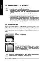
... to see that the CPU pins fit perfectly into the socket. The pin 1 location is positioned into position making sure that none are bent. K8 nForce4 SLI Series Motherboard - 14 - If you wish to set beyond the proper specifications, please do so according to your hardware specifications including the CPU, graphics card...
... to see that the CPU pins fit perfectly into the socket. The pin 1 location is positioned into position making sure that none are bent. K8 nForce4 SLI Series Motherboard - 14 - If you wish to set beyond the proper specifications, please do so according to your hardware specifications including the CPU, graphics card...

User Manual
Page 16
... one direction. A memory module can differ with the following conditions: 1. English 1-4 Installation of Memory Before installing the memory modules, please comply with each slot. K8 nForce4 SLI Series Motherboard - 16 - The memory capacity used can be used is switched off to lock the DIMM module. Insert the DIMM memory module vertically into...
... one direction. A memory module can differ with the following conditions: 1. English 1-4 Installation of Memory Before installing the memory modules, please comply with each slot. K8 nForce4 SLI Series Motherboard - 16 - The memory capacity used can be used is switched off to lock the DIMM module. Insert the DIMM memory module vertically into...
User Manual
Page 18
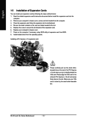
... the small whitedrawable bar at the end of Expansion Cards You can install your VGA card is locked by following the steps outlined below: 1. K8 nForce4 SLI Series Motherboard - 18 - Read the related expansion card's instruction document before install the expansion card into expansion slot in the slot. 5. Remove your computer's chassis...
... the small whitedrawable bar at the end of Expansion Cards You can install your VGA card is locked by following the steps outlined below: 1. K8 nForce4 SLI Series Motherboard - 18 - Read the related expansion card's instruction document before install the expansion card into expansion slot in the slot. 5. Remove your computer's chassis...

User Manual
Page 19
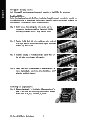
... GIGABYTE SLI switch module: You can run at up to provide enhanced performance. The SLI switch module has gold edge connectors on the GA-K8N Ulra-SLI/GA-K8N Pro-SLI/GA-K8N-SLI motherboard. SLI Mode: In SLI Mode, the two PCIE x 16 slots can find an SLI switch module socket inserted with an SLI bridge connector to enable SLI ... NVIDIA GPU (graphics processing unit) and the NVIDIA nForce4 chipset. As not all PCIE slots will depend on your system and the two SLI graphics cards. We do not recommend removing the SLI switch module from the motherboard because in that can run...
... GIGABYTE SLI switch module: You can run at up to provide enhanced performance. The SLI switch module has gold edge connectors on the GA-K8N Ulra-SLI/GA-K8N Pro-SLI/GA-K8N-SLI motherboard. SLI Mode: In SLI Mode, the two PCIE x 16 slots can find an SLI switch module socket inserted with an SLI bridge connector to enable SLI ... NVIDIA GPU (graphics processing unit) and the NVIDIA nForce4 chipset. As not all PCIE slots will depend on your system and the two SLI graphics cards. We do not recommend removing the SLI switch module from the motherboard because in that can run...
User Manual
Page 20
...Connecting Two Graphics Cards: Step 1: Observe the steps in "1-5 Installation of Expansion Cards" on page 16 and install two SLI-ready graphics cards of the module with the key in the SLI Mode direction. English III. Align the small notch at a 25o angle. Step 3: Insert the top edge of the... the socket. Step 1: Gently spread the retaining clips of the module until it away from the socket and insert it in the socket. K8 nForce4 SLI Series Motherboard - 20 - Step 4: Gently press down on your system is currrently supported by factory default, the first step to the PCIE_16_1 and...
...Connecting Two Graphics Cards: Step 1: Observe the steps in "1-5 Installation of Expansion Cards" on page 16 and install two SLI-ready graphics cards of the module with the key in the SLI Mode direction. English III. Align the small notch at a 25o angle. Step 3: Insert the top edge of the... the socket. Step 1: Gently spread the retaining clips of the module until it away from the socket and insert it in the socket. K8 nForce4 SLI Series Motherboard - 20 - Step 4: Gently press down on your system is currrently supported by factory default, the first step to the PCIE_16_1 and...

User Manual
Page 22
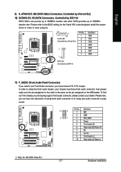
... port allows connection of 10/100/1000Mbps. Also make sure your OS supports USB controller. can be connected to an external Dolby Digital Decoder. K8 nForce4 SLI Series Motherboard - 22 - COMA (Serial Port) Connects to this connector. LAN Port 2 The provided Internet connection is capable of 10/100/ 1000Mbps. USB port ... to MIC In jack. SPDIF_I (SPDIF In) Use SPDIF In feature only when your OS does not support USB controller, please contact OS vendor for GA-K8N Ultra-SLI. have a standard USB interface. For more information please contact your OS or device(s) vendors.
... port allows connection of 10/100/1000Mbps. Also make sure your OS supports USB controller. can be connected to an external Dolby Digital Decoder. K8 nForce4 SLI Series Motherboard - 22 - COMA (Serial Port) Connects to this connector. LAN Port 2 The provided Internet connection is capable of 10/100/ 1000Mbps. USB port ... to MIC In jack. SPDIF_I (SPDIF In) Use SPDIF In feature only when your OS does not support USB controller, please contact OS vendor for GA-K8N Ultra-SLI. have a standard USB interface. For more information please contact your OS or device(s) vendors.
User Manual
Page 24
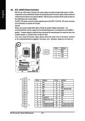
... +5V 1 13 11 +12V(Onlyfor24-pinATX) 23 +5V (Only for 24-pin ATX) 12 3.3V(Onlyfor24-pinATX) 24 GND(Only for 24-pin ATX) K8 nForce4 SLI Series Motherboard - 24 -
... +5V 1 13 11 +12V(Onlyfor24-pinATX) 23 +5V (Only for 24-pin ATX) 12 3.3V(Onlyfor24-pinATX) 24 GND(Only for 24-pin ATX) K8 nForce4 SLI Series Motherboard - 24 -
User Manual
Page 26
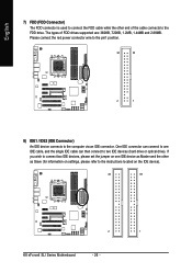
... device connects to the FDD drive. If you wish to connect two IDE devices, please set the jumper on the IDE device). 40 39 2 1 K8 nForce4 SLI Series Motherboard - 26 - One IDE connector can connect to one IDE cable, and the single IDE cable can then connect to the instructions located on...
... device connects to the FDD drive. If you wish to connect two IDE devices, please set the jumper on the IDE device). 40 39 2 1 K8 nForce4 SLI Series Motherboard - 26 - One IDE connector can connect to one IDE cable, and the single IDE cable can then connect to the instructions located on...
User Manual
Page 27
...refer to the BIOS setting for GA-K8N Ultra-SLI. - 27 - Hardware Installation Also please make sure the pin assigment on the cable is the same as the pin assigment on the MB header. English 9) S_ATA0/1/2/3_SB (SATA 3Gb/s Connectors, Controlled by nForce4 SLI) 10) SATA0/1/2/3_SII (SATA ...Front Audio (L) Rear Audio (L)/ Return L Only for the Serial ATA controller(s)and install the proper driver in order to work properly. 7 1 S_ATA_SB (Controlled by nForce4 SLI) 7 1 Pin No. 1 2 3 4 5 6 7 Definition GND TXP TXN GND RXN RXP GND SATA_SII (Controlled by Sil3114) SATA 3Gb/s can have ...
...refer to the BIOS setting for GA-K8N Ultra-SLI. - 27 - Hardware Installation Also please make sure the pin assigment on the cable is the same as the pin assigment on the MB header. English 9) S_ATA0/1/2/3_SB (SATA 3Gb/s Connectors, Controlled by nForce4 SLI) 10) SATA0/1/2/3_SII (SATA ...Front Audio (L) Rear Audio (L)/ Return L Only for the Serial ATA controller(s)and install the proper driver in order to work properly. 7 1 S_ATA_SB (Controlled by nForce4 SLI) 7 1 Pin No. 1 2 3 4 5 6 7 Definition GND TXP TXN GND RXN RXP GND SATA_SII (Controlled by Sil3114) SATA 3Gb/s can have ...
User Manual
Page 28
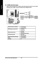
Pin 3: NC Pin 4: Data(-) Open: Normal Close: Reset Hardware System Open: Normal Close: Power On/Off Pin 1: LED anode(+) Pin 2: LED cathode(-) NC K8 nForce4 SLI Series Motherboard - 28 - HDHD+ Reset Switch IDE Hard Disk Active LED HD (IDE Hard Disk Active LED) (Blue) SPEAK (Speaker Connector) (Amber) RES (Reset Switch) (...
Pin 3: NC Pin 4: Data(-) Open: Normal Close: Reset Hardware System Open: Normal Close: Power On/Off Pin 1: LED anode(+) Pin 2: LED cathode(-) NC K8 nForce4 SLI Series Motherboard - 28 - HDHD+ Reset Switch IDE Hard Disk Active LED HD (IDE Hard Disk Active LED) (Blue) SPEAK (Speaker Connector) (Amber) RES (Reset Switch) (...
User Manual
Page 30
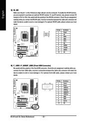
... cable, please contact your local dealer. 2 10 1 9 Pin No. 1 2 3 4 5 6 7 8 9 10 Definition Power Power USB DXUSB DyUSB DX+ USB Dy+ GND GND No Pin NC K8 nForce4 SLI Series Motherboard - 30 - To enable the IR/CIR function, you connect the front USB cable, incorrect connection between the cable and connector will make the...
... cable, please contact your local dealer. 2 10 1 9 Pin No. 1 2 3 4 5 6 7 8 9 10 Definition Power Power USB DXUSB DyUSB DX+ USB Dy+ GND GND No Pin NC K8 nForce4 SLI Series Motherboard - 30 - To enable the IR/CIR function, you connect the front USB cable, incorrect connection between the cable and connector will make the...
User Manual
Page 32
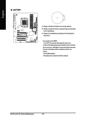
... the positive and negative pins in the battery holder to makethem short for one minute.) 3. Plug the power cord and turn ON the computer. K8 nForce4 SLI Series Motherboard - 32 - English 19) BATTERY Danger of used batteries according to the manufacturer's instructions. Dispose of explosion if battery is incorrectly replaced. Turn OFF...
... the positive and negative pins in the battery holder to makethem short for one minute.) 3. Plug the power cord and turn ON the computer. K8 nForce4 SLI Series Motherboard - 32 - English 19) BATTERY Danger of used batteries according to the manufacturer's instructions. Dispose of explosion if battery is incorrectly replaced. Turn OFF...
User Manual
Page 34
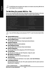
...'t find the setting you enter Award BIOS CMOS Setup Utility, the Main Menu (as figure below) will appear on the screen. K8 nForce4 SLI Series Motherboard - 34 - Only for GA-K8N Ultra-SLI. The Main Menu (For example: BIOS Ver. : F6a) Once you want, please press "Ctrl+F1" to accept or enter the ...sub-menu. Only for GA-K8N Pro-SLI. English The BIOS Setup menus described in this chapter are for reference only and may differ from the exact settings for your system, enable Top ...
...'t find the setting you enter Award BIOS CMOS Setup Utility, the Main Menu (as figure below) will appear on the screen. K8 nForce4 SLI Series Motherboard - 34 - Only for GA-K8N Ultra-SLI. The Main Menu (For example: BIOS Ver. : F6a) Once you want, please press "Ctrl+F1" to accept or enter the ...sub-menu. Only for GA-K8N Pro-SLI. English The BIOS Setup menus described in this chapter are for reference only and may differ from the exact settings for your system, enable Top ...

User Manual
Page 36
... 24-hour military- The four options are: CHS/LBA/Large/Auto(default:Auto) IDE Channel 2/3/4/5 Master IDE HDD Auto-Detection Press "Enter" to Dec. K8 nForce4 SLI Series Motherboard - 36 - to select this option for automatic device detection. Week The week, from Sun to set the access mode for faster system start...
... 24-hour military- The four options are: CHS/LBA/Large/Auto(default:Auto) IDE Channel 2/3/4/5 Master IDE HDD Auto-Detection Press "Enter" to Dec. K8 nForce4 SLI Series Motherboard - 36 - to select this option for automatic device detection. Week The week, from Sun to set the access mode for faster system start...

User Manual
Page 38
... your boot device priority by USB-ZIP. Note that there will not be any warning message if the drive installed is 360K. (Default value) K8 nForce4 SLI Series Motherboard - 38 - Hard Disk Select your boot device priority by NVIDIA Boot Age. Disabled Disable this menu. English 2-2 Advanced BIOS Features CMOS Setup Utility...
... your boot device priority by USB-ZIP. Note that there will not be any warning message if the drive installed is 360K. (Default value) K8 nForce4 SLI Series Motherboard - 38 - Hard Disk Select your boot device priority by NVIDIA Boot Age. Disabled Disable this menu. English 2-2 Advanced BIOS Features CMOS Setup Utility...
User Manual
Page 40
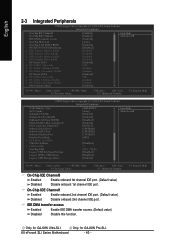
... IDE Channel1 Enabled Enable onboard 2nd channel IDE port. (Default value) Disabled Disable onboard 2nd channel IDE port. Only for GA-K8N Ultra-SLI. K8 nForce4 SLI Series Motherboard - 40 - F1: General Help Only for GA-K8N Pro-SLI. English 2-3 Integrated Peripherals CMOS Setup Utility-Copyright (C) 1984-2005 Award Software Integrated Peripherals On-Chip IDE Channel0 On-Chip...
... IDE Channel1 Enabled Enable onboard 2nd channel IDE port. (Default value) Disabled Disable onboard 2nd channel IDE port. Only for GA-K8N Ultra-SLI. K8 nForce4 SLI Series Motherboard - 40 - F1: General Help Only for GA-K8N Pro-SLI. English 2-3 Integrated Peripherals CMOS Setup Utility-Copyright (C) 1984-2005 Award Software Integrated Peripherals On-Chip IDE Channel0 On-Chip...
User Manual
Page 42
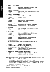
... set "NV SATA2 class code" to create RAID data drive or install O.S. OnBoard LAN Boot ROM This function decide whether to base memory(640K). K8 nForce4 SLI Series Motherboard - 42 - Disabled Disable this function. (Default value) SATA RAID-5/ATA controller (Controlled by Sil3114 chip) RAID-5 ATA Set Sil3114 Serial ATA Chip to.... Enabled Enable onboard Serial ATA Chip.(Default value) Disabled Disable onboard Serial ATA Chip. And manually set "NV SATA1 class code" to 0104. Only for GA-K8N Pro-SLI. Only for GA-K8N Ultra-SLI.
... set "NV SATA2 class code" to create RAID data drive or install O.S. OnBoard LAN Boot ROM This function decide whether to base memory(640K). K8 nForce4 SLI Series Motherboard - 42 - Disabled Disable this function. (Default value) SATA RAID-5/ATA controller (Controlled by Sil3114 chip) RAID-5 ATA Set Sil3114 Serial ATA Chip to.... Enabled Enable onboard Serial ATA Chip.(Default value) Disabled Disable onboard Serial ATA Chip. And manually set "NV SATA1 class code" to 0104. Only for GA-K8N Pro-SLI. Only for GA-K8N Ultra-SLI.
User Manual
Page 44
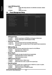
... as wake up system from suspend type. English Legacy USB Storage detect Enabled Enable USB storage detection in Date/Time to POWER ON system. K8 nForce4 SLI Series Motherboard - 44 - Enter suspend if button is Enabled. Modem Ring On An incoming call via modem can set "Resume by Alarm" item to enabled...
... as wake up system from suspend type. English Legacy USB Storage detect Enabled Enable USB storage detection in Date/Time to POWER ON system. K8 nForce4 SLI Series Motherboard - 44 - Enter suspend if button is Enabled. Modem Ring On An incoming call via modem can set "Resume by Alarm" item to enabled...