Manual
Page 6
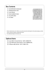
The box contents are for reference only. Box Contents GA-H67MA-D2H motherboard Motherboard driver disk User's Manual Quick Installation Guide Two SATA cables I/O Shield • The box contents above are subject to change without notice. • The motherboard image is for reference only and the actual items shall depend on the product package you obtain. Optional Items 2-port USB 2.0 bracket (Part No. 12CR1-1UB030-5*R) 2-port SATA power cable (Part No. 12CF1-2SERPW-0*R) COM port cable (Part No. 12CF1-1CM001-3*R) - 6 -
The box contents are for reference only. Box Contents GA-H67MA-D2H motherboard Motherboard driver disk User's Manual Quick Installation Guide Two SATA cables I/O Shield • The box contents above are subject to change without notice. • The motherboard image is for reference only and the actual items shall depend on the product package you obtain. Optional Items 2-port USB 2.0 bracket (Part No. 12CR1-1UB030-5*R) 2-port SATA power cable (Part No. 12CF1-2SERPW-0*R) COM port cable (Part No. 12CF1-1CM001-3*R) - 6 -
Manual
Page 8
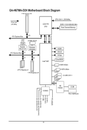
GA-H67MA-D2H Motherboard Block Diagram 1 PCI Express x16 PCIe CLK (100 MHz) LGA1155 CPU CPU CLK+/- (100 MHz) DDR3 1333/1066/800 MHz Dual Channel Memory PCI Express Bus x16 LAN 2 USB 3.0/2.0 RJ45 Realtek RTL8111E Renesas D720200 PCI Express Bus x1 x1 x1 x4 Intel® H67 2 PCI Express x1 1 PCI Express x4 DMI Interface FDI Interface HDMI DVI-D D-Sub Dual BIOS 2 SATA 6Gb/s 4 SATA 3Gb/s 12 USB 2.0/1.1 CODEC LPC Bus iTE IT8728 COM PS/2 KB/Mouse Surround Speaker Out Center/Subwoofer Speaker Out Side Speaker Out MIC Line Out Line In S/PDIF Out - 8 -
GA-H67MA-D2H Motherboard Block Diagram 1 PCI Express x16 PCIe CLK (100 MHz) LGA1155 CPU CPU CLK+/- (100 MHz) DDR3 1333/1066/800 MHz Dual Channel Memory PCI Express Bus x16 LAN 2 USB 3.0/2.0 RJ45 Realtek RTL8111E Renesas D720200 PCI Express Bus x1 x1 x1 x4 Intel® H67 2 PCI Express x1 1 PCI Express x4 DMI Interface FDI Interface HDMI DVI-D D-Sub Dual BIOS 2 SATA 6Gb/s 4 SATA 3Gb/s 12 USB 2.0/1.1 CODEC LPC Bus iTE IT8728 COM PS/2 KB/Mouse Surround Speaker Out Center/Subwoofer Speaker Out Side Speaker Out MIC Line Out Line In S/PDIF Out - 8 -
Manual
Page 11
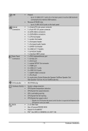
...fan header w 1 x system fan header w 1 x front panel header w 1 x front panel audio header w 1 x S/PDIF Out header w 4 x USB 2.0/1.1 headers w 1 x serial port header w 1 x clearing CMOS jumper Back Panel w 1 x PS/2 keyboard/mouse port Connectors w 1 x D-Sub port w... 1 x DVI-D port w 1 x optical S/PDIF Out connector w 1 x HDMI port w 4 x USB 2.0/1.1 ports w 2 x USB 3.0/2.0 ports w 1 x eSATA 3Gb/s connector w 1 x RJ-45 port w 6 x audio jacks (Center/Subwoofer Speaker Out/Rear Speaker...
...fan header w 1 x system fan header w 1 x front panel header w 1 x front panel audio header w 1 x S/PDIF Out header w 4 x USB 2.0/1.1 headers w 1 x serial port header w 1 x clearing CMOS jumper Back Panel w 1 x PS/2 keyboard/mouse port Connectors w 1 x D-Sub port w... 1 x DVI-D port w 1 x optical S/PDIF Out connector w 1 x HDMI port w 4 x USB 2.0/1.1 ports w 2 x USB 3.0/2.0 ports w 1 x eSATA 3Gb/s connector w 1 x RJ-45 port w 6 x audio jacks (Center/Subwoofer Speaker Out/Rear Speaker...

Manual
Page 19
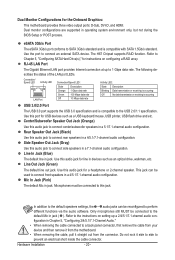
...supports D-Sub connection to an external audio system that supports digital optical audio. Hardware Installation 1-6 Back Panel Connectors USB 2.0/1.1 Port The USB port supports the USB 2.0/1.1 specification. Optical S/PDIF Out Connector This connector provides digital audio out to this port. Connect the HDMI audio... the monitor being used . • After installing the HDMI device, make sure the default device for USB devices such as a USB keyboard/mouse, USB printer, USB flash drive and etc. HDMI Port The HDMI (High-Definition Multimedia Interface) provides an all-digital audio/...
...supports D-Sub connection to an external audio system that supports digital optical audio. Hardware Installation 1-6 Back Panel Connectors USB 2.0/1.1 Port The USB port supports the USB 2.0/1.1 specification. Optical S/PDIF Out Connector This connector provides digital audio out to this port. Connect the HDMI audio... the monitor being used . • After installing the HDMI device, make sure the default device for USB devices such as a USB keyboard/mouse, USB printer, USB flash drive and etc. HDMI Port The HDMI (High-Definition Multimedia Interface) provides an all-digital audio/...
Manual
Page 20
...LED: State Description Blinking Data transmission or receiving is occurring Off No data transmission or receiving is occurring USB 3.0/2.0 Port The USB 3.0 port supports the USB 3.0 specification and is compatible with SATA 1.5Gb/s standard. The following describes the states of the LAN... connected to connect side speakers in a 4/5.1/7.1-channel audio configuration. Center/Subwoofer Speaker Out Jack (Orange) Use this audio jack to the USB 2.0/1.1 specification. Hardware Installation - 20 - Dual monitor configurations are supported in jack ( ). eSATA 3Gb/s Port The eSATA 3Gb/s port...
...LED: State Description Blinking Data transmission or receiving is occurring Off No data transmission or receiving is occurring USB 3.0/2.0 Port The USB 3.0 port supports the USB 3.0 specification and is compatible with SATA 1.5Gb/s standard. The following describes the states of the LAN... connected to connect side speakers in a 4/5.1/7.1-channel audio configuration. Center/Subwoofer Speaker Out Jack (Orange) Use this audio jack to the USB 2.0/1.1 specification. Hardware Installation - 20 - Dual monitor configurations are supported in jack ( ). eSATA 3Gb/s Port The eSATA 3Gb/s port...

Manual
Page 27
...cord from the power outlet to prevent damage to USB 2.0/1.1 specification. Definition 1 NDCD- 9 1 2 NSIN 10 2 3 NSOUT 4 NDTR- 5 GND 6 NDSR- 7 NRTS- 8 NCTS- 9 NRI- 10 No Pin - 27 - Definition 1 Power (5V) 2 Power (5V) 9 1 10 2 3 USB DX- 4 USB DY- 5 USB DX+ 6 USB DY+ 7 GND 8 GND 9 No Pin... 10 NC When the system is in S4/S5 mode, only the USB ports routed to the F_USB1 header can provide two USB ports via an optional COM port cable.
...cord from the power outlet to prevent damage to USB 2.0/1.1 specification. Definition 1 NDCD- 9 1 2 NSIN 10 2 3 NSOUT 4 NDTR- 5 GND 6 NDSR- 7 NRTS- 8 NCTS- 9 NRI- 10 No Pin - 27 - Definition 1 Power (5V) 2 Power (5V) 9 1 10 2 3 USB DX- 4 USB DY- 5 USB DX+ 6 USB DY+ 7 GND 8 GND 9 No Pin... 10 NC When the system is in S4/S5 mode, only the USB ports routed to the F_USB1 header can provide two USB ports via an optional COM port cable.
Manual
Page 32
..., advanced features available on the CPU, and the primary display adapter. Integrated Peripherals Use this menu to configure all peripheral devices, such as SATA, USB, integrated audio, and integrated LAN, etc. Power Management Setup Use this menu to configure all the power-saving functions. PC Health Status Use...
..., advanced features available on the CPU, and the primary display adapter. Integrated Peripherals Use this menu to configure all peripheral devices, such as SATA, USB, integrated audio, and integrated LAN, etc. Power Management Setup Use this menu to configure all the power-saving functions. PC Health Status Use...

Manual
Page 43
... For HDD (Secs) Full Screen LOGO Show Init Display First Onboard VGA On-Chip Frame Buffer Size [Press Enter] [Disabled] [Hard Disk] [CDROM] [USB-FDD] [Setup] [Disabled] [Disabled] [Enabled] [0] [Enabled] [PCIE x16] [Enable If No Ext PEG] [64MB+2MB for GTT] Item Help ...This feature allows your hard drive. After configuring this menu when finished. HDD S.M.A.R.T. BIOS Setup Options are: Hard Disk, CDROM, USB-FDD, USB-ZIP, USB-CDROM, USBHDD, Legacy LAN, Disabled. to accept. Password Check Specifies whether a password is required for booting the system and for...
... For HDD (Secs) Full Screen LOGO Show Init Display First Onboard VGA On-Chip Frame Buffer Size [Press Enter] [Disabled] [Hard Disk] [CDROM] [USB-FDD] [Setup] [Disabled] [Disabled] [Enabled] [0] [Enabled] [PCIE x16] [Enable If No Ext PEG] [64MB+2MB for GTT] Item Help ...This feature allows your hard drive. After configuring this menu when finished. HDD S.M.A.R.T. BIOS Setup Options are: Hard Disk, CDROM, USB-FDD, USB-ZIP, USB-CDROM, USBHDD, Legacy LAN, Disabled. to accept. Password Check Specifies whether a password is required for booting the system and for...

Manual
Page 45
...(Default: Disabled) PCH SATA Control Mode (Intel H67 Chipset) Enables or disables RAID for the SATA controllers. For details on using the GIGABYTE X.H.D utility, refer to Enabled, the PCH SATA Control Mode item below will turn off all of the integrated SATA controllers. AHCI Configures ...interface specification that do not support Native mode. SATA Port0-3 Native Mode (Intel H67 Chipset) Specifies the operating mode of the USB functionalities below. Enabled Allows the SATA controllers to enable advanced Serial ATA features such as Native Command Queuing and hot plug. ...
...(Default: Disabled) PCH SATA Control Mode (Intel H67 Chipset) Enables or disables RAID for the SATA controllers. For details on using the GIGABYTE X.H.D utility, refer to Enabled, the PCH SATA Control Mode item below will turn off all of the integrated SATA controllers. AHCI Configures ...interface specification that do not support Native mode. SATA Port0-3 Native Mode (Intel H67 Chipset) Specifies the operating mode of the USB functionalities below. Enabled Allows the SATA controllers to enable advanced Serial ATA features such as Native Command Queuing and hot plug. ...
Manual
Page 46
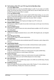
... 1-2. Example: Part1-2 Status = Short / Length = 2m Explanation: A fault or short might occur at a speed of the attached LAN cable. USB Storage Function Determines whether to detect USB storage devices, including USB flash drives and USB hard drives during the POST. (Default: Enabled) Azalia Codec Enables or disables the onboard audio function. (Default: Auto) If...
... 1-2. Example: Part1-2 Status = Short / Length = 2m Explanation: A fault or short might occur at a speed of the attached LAN cable. USB Storage Function Determines whether to detect USB storage devices, including USB flash drives and USB hard drives during the POST. (Default: Enabled) Azalia Codec Enables or disables the onboard audio function. (Default: Auto) If...

Manual
Page 47
Options are: Auto, 3F8/IRQ4 (default), 2F8/IRQ3, 3E8/IRQ4, 2E8/IRQ3, Disabled. - 47 - Onboard LAN Boot ROM Allows you to decide whether to activate the boot ROM integrated with the onboard LAN chip. (Default: Disabled) Onboard USB 3.0 Controller (Renesas D720200 USB Controller) Enables or disables the Renesas D720200 USB controller. (Default: Enabled) Onboard Serial Port 1 Enables or disables the first serial port and specifies its base I/O address and corresponding interrupt. BIOS Setup
Options are: Auto, 3F8/IRQ4 (default), 2F8/IRQ3, 3E8/IRQ4, 2E8/IRQ3, Disabled. - 47 - Onboard LAN Boot ROM Allows you to decide whether to activate the boot ROM integrated with the onboard LAN chip. (Default: Disabled) Onboard USB 3.0 Controller (Renesas D720200 USB Controller) Enables or disables the Renesas D720200 USB controller. (Default: Enabled) Onboard Serial Port 1 Enables or disables the first serial port and specifies its base I/O address and corresponding interrupt. BIOS Setup
Manual
Page 55
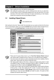
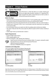
Failure to do so may affect the driver installation. • Some device drivers will appear asking whether to install new GIGABYTE utilities. After the system restart, "Xpress Install" will continue to install other drivers. • After "Xpress Install" installs all of the .... The driver Autorun screen is installing the drivers. You can click the Install All button and "Xpress Install" will then autodetect and install the USB 2.0 driver.) - 55 - the Found New Hardware Wizard) displayed when "Xpress Install" is automatically displayed which looks like that are recommended to ...
Failure to do so may affect the driver installation. • Some device drivers will appear asking whether to install new GIGABYTE utilities. After the system restart, "Xpress Install" will continue to install other drivers. • After "Xpress Install" installs all of the .... The driver Autorun screen is installing the drivers. You can click the Install All button and "Xpress Install" will then autodetect and install the USB 2.0 driver.) - 55 - the Found New Hardware Wizard) displayed when "Xpress Install" is automatically displayed which looks like that are recommended to ...
Manual
Page 59
... data and perform restoration of system memory • VESA compatible graphics card • Windows XP with Xpress Recovery cannot be restored using Xpress Recovery2. • USB hard drives are not supported. • Hard drives in the following sequence: The first SATA connector, the second SATA connector and so forth. Installation and...
... data and perform restoration of system memory • VESA compatible graphics card • Windows XP with Xpress Recovery cannot be restored using Xpress Recovery2. • USB hard drives are not supported. • Hard drives in the following sequence: The first SATA connector, the second SATA connector and so forth. Installation and...
Manual
Page 62
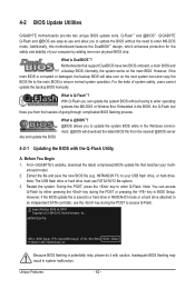
...-DOS or Window first. Unique Features - 62 - What is potentially risky, please do it with the Q-Flash Utility A. H67MAD2H.F1) to enter Q-Flash. H67MA-D2H F4j . . . . : BIOS Setup : XpressRecovery2 : Boot Menu : Qflash 11/16/2010-H67-7A89VG0AC-00 Because BIOS flashing is DualBIOS™? Normally, ... drive, or hard drive. Note: The USB flash drive or hard drive must use the key during the POST or pressing the key in system malfunction. 4-2 BIOS Update Utilities GIGABYTE motherboards provide two unique BIOS update tools, Q-Flash™ and @BIOS™. For the sake of...
...-DOS or Window first. Unique Features - 62 - What is potentially risky, please do it with the Q-Flash Utility A. H67MAD2H.F1) to enter Q-Flash. H67MA-D2H F4j . . . . : BIOS Setup : XpressRecovery2 : Boot Menu : Qflash 11/16/2010-H67-7A89VG0AC-00 Because BIOS flashing is DualBIOS™? Normally, ... drive, or hard drive. Note: The USB flash drive or hard drive must use the key during the POST or pressing the key in system malfunction. 4-2 BIOS Update Utilities GIGABYTE motherboards provide two unique BIOS update tools, Q-Flash™ and @BIOS™. For the sake of...
Manual
Page 63
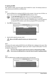
...F10:Power Off 3. Unique Features Select the BIOS update file and press . CoaodpyCMBIOOSS DcoemfapuletteEdn-aPbaless !! Select HDD 1-0 and press . B. Insert the USB flash drive containing the BIOS file into the computer. Q-Flash Utility v2.19 Flash Type/Size MXIC 25L3206E 4M Keep0 DfilMe(Is)DfaotuandEnable HDD 1-0 ... the BIOS When updating the BIOS, choose the location where the BIOS file is complete, press any key to return to a USB flash drive. The following procedure assumes that you sure to access Q-Flash. 2. In the main menu of the system reading the...
...F10:Power Off 3. Unique Features Select the BIOS update file and press . CoaodpyCMBIOOSS DcoemfapuletteEdn-aPbaless !! Select HDD 1-0 and press . B. Insert the USB flash drive containing the BIOS file into the computer. Q-Flash Utility v2.19 Flash Type/Size MXIC 25L3206E 4M Keep0 DfilMe(Is)DfaotuandEnable HDD 1-0 ... the BIOS When updating the BIOS, choose the location where the BIOS file is complete, press any key to return to a USB flash drive. The following procedure assumes that you sure to access Q-Flash. 2. In the main menu of the system reading the...

Manual
Page 78
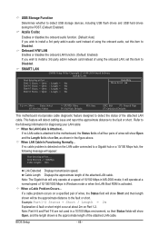
...-2010 Award Software Integrated Peripherals eXtreme Hard Drive (XHD) PCH SATA Control Mode SATA Port0-3 Native Mode USB Controllers USB Legacy Function USB Storage Function Azalia Codec Onboard H/W LAN } SMART LAN Onboard LAN Boot ROM Onboard USB 3.0 Controller Onboard Serial Port 1 [Disabled] [RAID(XHD)] [Enabled] [Enabled] [Enabled] [Enabled] [Auto] [Enabled] [Press Enter] [Disabled] [Enabled...
...-2010 Award Software Integrated Peripherals eXtreme Hard Drive (XHD) PCH SATA Control Mode SATA Port0-3 Native Mode USB Controllers USB Legacy Function USB Storage Function Azalia Codec Onboard H/W LAN } SMART LAN Onboard LAN Boot ROM Onboard USB 3.0 Controller Onboard Serial Port 1 [Disabled] [RAID(XHD)] [Enabled] [Enabled] [Enabled] [Enabled] [Auto] [Enabled] [Press Enter] [Disabled] [Enabled...
Manual
Page 85
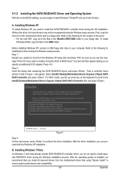
... 2: Insert the floppy disk containing the SATA RAID/AHCI driver and press . Windows Setup You have chosen to a floppy disk. Before installing Windows XP, connect a USB floppy disk drive to your floppy disk. Refer to the Intel(R) Desktop/Workstation/Server Express Chipset SATA AHCI Controller item and press . Select Intel(R) Desktop...
... 2: Insert the floppy disk containing the SATA RAID/AHCI driver and press . Windows Setup You have chosen to a floppy disk. Before installing Windows XP, connect a USB floppy disk drive to your floppy disk. Refer to the Intel(R) Desktop/Workstation/Server Express Chipset SATA AHCI Controller item and press . Select Intel(R) Desktop...


