
Manual
Page 6
Box Contents GA-H67A-UD3H-B3 motherboard Motherboard driver disk User's Manual Quick Installation Guide Four SATA cables I/O Shield • The box contents above are subject to change without notice. • The motherboard image is for reference only and the actual items shall depend on the product package you obtain. The box contents are for reference only. Optional Items 2-port USB 2.0 bracket (Part No. 12CR1-1UB030-5*R) 2-port IEEE 1394a bracket (Part No. 12CF1-1IE008-0*R) 2-port SATA power cable (Part No. 12CF1-2SERPW-0*R) COM port cable (Part No. 12CF1-1CM001-3*R) - 6 -
Box Contents GA-H67A-UD3H-B3 motherboard Motherboard driver disk User's Manual Quick Installation Guide Four SATA cables I/O Shield • The box contents above are subject to change without notice. • The motherboard image is for reference only and the actual items shall depend on the product package you obtain. The box contents are for reference only. Optional Items 2-port USB 2.0 bracket (Part No. 12CR1-1UB030-5*R) 2-port IEEE 1394a bracket (Part No. 12CF1-1IE008-0*R) 2-port SATA power cable (Part No. 12CF1-2SERPW-0*R) COM port cable (Part No. 12CF1-1CM001-3*R) - 6 -

Manual
Page 8
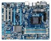
GA-H67A-UD3H-B3 Motherboard Block Diagram 1 PCI Express x16 PCIe CLK (100 MHz) LGA1155 CPU CPU CLK+/- (100 MHz) DDR3 1333/1066/800 MHz Dual Channel Memory PCI Express Bus x16 1 PCI Express x4 2 PCI Express x1 or 2 USB 3.0/2.0 x4 x1 Renesas D720200 Switch PCI Express Bus x1 x1 x1 x1 Realtek... PCI Bus TSB43AB23 Intel® H67 CODEC DMI Interface FDI Interface DisplayPort HDMI DVI-D D-Sub Dual BIOS 2 SATA 6Gb/s 4 SATA 3Gb/s 14 USB 2.0/1.1 LPC Bus iTE IT8728 COM PS/2 KB/Mouse 3 IEEE 1394a Surround Speaker Out Center/Subwoofer Speaker Out Side Speaker Out MIC Line Out Line ...
GA-H67A-UD3H-B3 Motherboard Block Diagram 1 PCI Express x16 PCIe CLK (100 MHz) LGA1155 CPU CPU CLK+/- (100 MHz) DDR3 1333/1066/800 MHz Dual Channel Memory PCI Express Bus x16 1 PCI Express x4 2 PCI Express x1 or 2 USB 3.0/2.0 x4 x1 Renesas D720200 Switch PCI Express Bus x1 x1 x1 x1 Realtek... PCI Bus TSB43AB23 Intel® H67 CODEC DMI Interface FDI Interface DisplayPort HDMI DVI-D D-Sub Dual BIOS 2 SATA 6Gb/s 4 SATA 3Gb/s 14 USB 2.0/1.1 LPC Bus iTE IT8728 COM PS/2 KB/Mouse 3 IEEE 1394a Surround Speaker Out Center/Subwoofer Speaker Out Side Speaker Out MIC Line Out Line ...

Manual
Page 11
... headers w 1 x power fan header w 1 x front panel header w 1 x front panel audio header w 1 x S/PDIF Out header w 5 x USB 2.0/1.1 headers w 2 x IEEE 1394a headers w 1 x serial port header w 1 x clearing CMOS jumper Back Panel w 1 x PS/2 keyboard/mouse port Connectors... w 1 x DVI-D port w 1 x optical S/PDIF Out connector w 1 x HDMI port w 1 x DisplayPort w 4 x USB 2.0/1.1 ports w 2 x USB 3.0/2.0 ports w 1 x IEEE 1394a port w 1 x eSATA 3Gb/s connector w 1 x RJ-45 port w 6 x audio jacks...
... headers w 1 x power fan header w 1 x front panel header w 1 x front panel audio header w 1 x S/PDIF Out header w 5 x USB 2.0/1.1 headers w 2 x IEEE 1394a headers w 1 x serial port header w 1 x clearing CMOS jumper Back Panel w 1 x PS/2 keyboard/mouse port Connectors... w 1 x DVI-D port w 1 x optical S/PDIF Out connector w 1 x HDMI port w 1 x DisplayPort w 4 x USB 2.0/1.1 ports w 2 x USB 3.0/2.0 ports w 1 x IEEE 1394a port w 1 x eSATA 3Gb/s connector w 1 x RJ-45 port w 6 x audio jacks...

Manual
Page 19
... HDMI audio output only supports AC3, DTS and 2-channel-LPCM formats. (AC3 and DTS require the use of an external decoder for USB devices such as a USB keyboard/mouse, USB printer, USB flash drive and etc. DVI-D Port (Note) The DVI-D port conforms to transmit the uncompressed audio/video signals and is the HDMI...
... HDMI audio output only supports AC3, DTS and 2-channel-LPCM formats. (AC3 and DTS require the use of an external decoder for USB devices such as a USB keyboard/mouse, USB printer, USB flash drive and etc. DVI-D Port (Note) The DVI-D port conforms to transmit the uncompressed audio/video signals and is the HDMI...

Manual
Page 20
...example, in Windows 7, go to Start>Control Panel>Hardware and Sound>Sound>Playback and set the DisplayPort device as a USB keyboard/mouse, USB printer, USB flash drive and etc. Dual monitor configurations are supported in a 7.1-channel audio configuration. eSATA 3Gb/s Port The eSATA...LED: State Description Blinking Data transmission or receiving is occurring Off No data transmission or receiving is occurring USB 3.0/2.0 Port The USB 3.0 port supports the USB 3.0 specification and is compatible to connect center/subwoofer speakers in a 4/5.1/7.1-channel audio configuration. Refer to ...
...example, in Windows 7, go to Start>Control Panel>Hardware and Sound>Sound>Playback and set the DisplayPort device as a USB keyboard/mouse, USB printer, USB flash drive and etc. Dual monitor configurations are supported in a 7.1-channel audio configuration. eSATA 3Gb/s Port The eSATA...LED: State Description Blinking Data transmission or receiving is occurring Off No data transmission or receiving is occurring USB 3.0/2.0 Port The USB 3.0 port supports the USB 3.0 specification and is compatible to connect center/subwoofer speakers in a 4/5.1/7.1-channel audio configuration. Refer to ...

Manual
Page 28
... of a single plug. If your chassis provides an AC'97 front panel audio module, refer to the instructions on how to USB 2.0/1.1 specification. Pin No. For information about connecting the front panel audio module that has separated connectors on both of the motherboard header...- For HD Front Panel Audio: For AC'97 Front Panel Audio: Pin No. Definition 1 Power (5V) 2 Power (5V) 9 1 10 2 3 USB DX- 4 USB DY- 5 USB DX+ 6 USB DY+ 7 GND 8 GND 9 No Pin 10 NC When the system is in Chapter 5, "Configuring 2/4/5.1/7.1-Channel Audio." • Audio signals will make the ...
... of a single plug. If your chassis provides an AC'97 front panel audio module, refer to the instructions on how to USB 2.0/1.1 specification. Pin No. For information about connecting the front panel audio module that has separated connectors on both of the motherboard header...- For HD Front Panel Audio: For AC'97 Front Panel Audio: Pin No. Definition 1 Power (5V) 2 Power (5V) 9 1 10 2 3 USB DX- 4 USB DY- 5 USB DX+ 6 USB DY+ 7 GND 8 GND 9 No Pin 10 NC When the system is in Chapter 5, "Configuring 2/4/5.1/7.1-Channel Audio." • Audio signals will make the ...

Manual
Page 29
...- 10 No Pin - 29 - Definition 1 TPA+ 9 1 2 TPA- 10 2 3 GND 4 GND 5 TPB+ 6 TPB- 7 Power (12V) 8 Power (12V) 9 No Pin 10 GND • Do not plug the USB bracket cable into the IEEE 1394a header. • Prior to installing the IEEE 1394a bracket, be sure to turn off your computer and unplug the...
...- 10 No Pin - 29 - Definition 1 TPA+ 9 1 2 TPA- 10 2 3 GND 4 GND 5 TPB+ 6 TPB- 7 Power (12V) 8 Power (12V) 9 No Pin 10 GND • Do not plug the USB bracket cable into the IEEE 1394a header. • Prior to installing the IEEE 1394a bracket, be sure to turn off your computer and unplug the...

Manual
Page 34
..., advanced features available on the CPU, and the primary display adapter. Integrated Peripherals Use this menu to configure all peripheral devices, such as SATA, USB, integrated audio, and integrated LAN, etc. Power Management Setup Use this menu to configure all changes and the previous settings remain in the BIOS...
..., advanced features available on the CPU, and the primary display adapter. Integrated Peripherals Use this menu to configure all peripheral devices, such as SATA, USB, integrated audio, and integrated LAN, etc. Power Management Setup Use this menu to configure all changes and the previous settings remain in the BIOS...

Manual
Page 45
... (Note) Delay For HDD (Secs) Full Screen LOGO Show Init Display First Onboard VGA On-Chip Frame Buffer Size [Press Enter] [Disabled] [Hard Disk] [CDROM] [USB-FDD] [Setup] [Disabled] [Disabled] [Enabled] [0] [Enabled] [PCI] [Enable If No Ext PEG] [64MB+2MB for daily use. BIOS Setup 2-5 Advanced BIOS Features CMOS Setup Utility... sequence of Smart 6™. (Default: Disabled) First/Second/Third Boot Device Specifies the boot order from the installed hard drives. Options are: Hard Disk, CDROM, USB-FDD, USB-ZIP, USB-CDROM, USBHDD, Legacy LAN, Disabled.
... (Note) Delay For HDD (Secs) Full Screen LOGO Show Init Display First Onboard VGA On-Chip Frame Buffer Size [Press Enter] [Disabled] [Hard Disk] [CDROM] [USB-FDD] [Setup] [Disabled] [Disabled] [Enabled] [0] [Enabled] [PCI] [Enable If No Ext PEG] [64MB+2MB for daily use. BIOS Setup 2-5 Advanced BIOS Features CMOS Setup Utility... sequence of Smart 6™. (Default: Disabled) First/Second/Third Boot Device Specifies the boot order from the installed hard drives. Options are: Hard Disk, CDROM, USB-FDD, USB-ZIP, USB-CDROM, USBHDD, Legacy LAN, Disabled.

Manual
Page 47
...SATA controllers integrated in the Intel H67 Chipset. SATA Port0-3 Native Mode (Intel H67 Chipset) Specifies the operating mode of the USB functionalities below will turn off all of the integrated SATA controllers. When set to RAID(XHD) automatically. Enabled Allows the SATA ...controllers to operate in Legacy IDE mode. For details on using the GIGABYTE X.H.D utility, refer to Chaper 4, "eXtreme Hard Drive (X.H.D)." (Default: Disabled) PCH SATA Control Mode (Intel H67 Chipset) Enables or disables...
...SATA controllers integrated in the Intel H67 Chipset. SATA Port0-3 Native Mode (Intel H67 Chipset) Specifies the operating mode of the USB functionalities below will turn off all of the integrated SATA controllers. When set to RAID(XHD) automatically. Enabled Allows the SATA ...controllers to operate in Legacy IDE mode. For details on using the GIGABYTE X.H.D utility, refer to Chaper 4, "eXtreme Hard Drive (X.H.D)." (Default: Disabled) PCH SATA Control Mode (Intel H67 Chipset) Enables or disables...

Manual
Page 48
... of using the onboard LAN, set this item to the fault or short. When LAN Cable Is Functioning Normally... USB Storage Function Determines whether to detect USB storage devices, including USB flash drives and USB hard drives during the POST. (Default: Enabled) Azalia Codec Enables or disables the onboard audio function. (Default: Auto) If...
... of using the onboard LAN, set this item to the fault or short. When LAN Cable Is Functioning Normally... USB Storage Function Determines whether to detect USB storage devices, including USB flash drives and USB hard drives during the POST. (Default: Enabled) Azalia Codec Enables or disables the onboard audio function. (Default: Auto) If...

Manual
Page 49
... field will be the approximate distance to activate the boot ROM integrated with the onboard LAN chip. (Default: Disabled) Onboard USB 3.0 Controller (Renesas D720200 USB Controller) Enables or disables the Renesas D720200 USB controller. (Default: Enabled) Onboard Serial Port 1 Enables or disables the first serial port and specifies its base I/O address and corresponding...
... field will be the approximate distance to activate the boot ROM integrated with the onboard LAN chip. (Default: Disabled) Onboard USB 3.0 Controller (Renesas D720200 USB Controller) Enables or disables the Renesas D720200 USB controller. (Default: Enabled) Onboard Serial Port 1 Enables or disables the first serial port and specifies its base I/O address and corresponding...

Manual
Page 57
...system and then list all the recommended drivers. Click Yes to install new GIGABYTE utilities. After the system restart, "Xpress Install" will continue to install on the Application Software page later. • For USB 2.0 driver support under the Windows XP operating system, please install the Windows...system, insert the motherboard driver disk into your mouse and select Uninstall) and restart the system. (The system will then autodetect and install the USB 2.0 driver.) - 57 - After installing the SP1 (or later), if a question mark still exists in Universal Serial Bus Controller in the ...
...system and then list all the recommended drivers. Click Yes to install new GIGABYTE utilities. After the system restart, "Xpress Install" will continue to install on the Application Software page later. • For USB 2.0 driver support under the Windows XP operating system, please install the Windows...system, insert the motherboard driver disk into your mouse and select Uninstall) and restart the system. (The system will then autodetect and install the USB 2.0 driver.) - 57 - After installing the SP1 (or later), if a question mark still exists in Universal Serial Bus Controller in the ...

Manual
Page 61
... data on the amount of system memory • VESA compatible graphics card • Windows XP with Xpress Recovery cannot be restored using Xpress Recovery2. • USB hard drives are not supported. • Hard drives in the following sequence: The first SATA connector, the second SATA connector and so forth. System Requirements...
... data on the amount of system memory • VESA compatible graphics card • Windows XP with Xpress Recovery cannot be restored using Xpress Recovery2. • USB hard drives are not supported. • Hard drives in the following sequence: The first SATA connector, the second SATA connector and so forth. System Requirements...

Manual
Page 64
... in the Windows environment. @BIOS will download the latest BIOS file from the hassles of going through complicated BIOS flashing process. Note: The USB flash drive or hard drive must use and allow you from the nearest @BIOS server 4-2-1 Updating the BIOS with caution. Note: You can...BIOS and a backup BIOS. However, if the main BIOS is potentially risky, please do it with the Q-Flash Utility A. GIGABYTE Q-Flash and @BIOS are easy-to-use FAT32/16/12 file system. 3. H67A-UD3H-B3 F5e . . . . : BIOS Setup : XpressRecovery2 : Boot Menu : Qflash 11/16/2010-H67-7A89UG06C-00 Because ...
... in the Windows environment. @BIOS will download the latest BIOS file from the hassles of going through complicated BIOS flashing process. Note: The USB flash drive or hard drive must use and allow you from the nearest @BIOS server 4-2-1 Updating the BIOS with caution. Note: You can...BIOS and a backup BIOS. However, if the main BIOS is potentially risky, please do it with the Q-Flash Utility A. GIGABYTE Q-Flash and @BIOS are easy-to-use FAT32/16/12 file system. 3. H67A-UD3H-B3 F5e . . . . : BIOS Setup : XpressRecovery2 : Boot Menu : Qflash 11/16/2010-H67-7A89UG06C-00 Because ...
Manual
Page 65
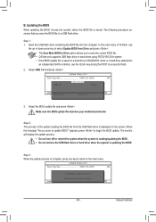
... Unique Features Step 1: 1. Select the BIOS update file and press . When the message "Are you save the current BIOS file. • Q-Flash only supports USB flash drive or hard drives using FAT32/16/12 file system. • If the BIOS update file is saved to a hard drive in RAID/AHCI...the BIOS, choose the location where the BIOS file is updating the BIOS. Select HDD 1-0 and press . The following procedure assumes that you sure to a USB flash drive. Step 2: The process of Q-Flash, use the key during the POST to Drive Enter : Run hi:Move Total size : 0 ESC:Reset Free...
... Unique Features Step 1: 1. Select the BIOS update file and press . When the message "Are you save the current BIOS file. • Q-Flash only supports USB flash drive or hard drives using FAT32/16/12 file system. • If the BIOS update file is saved to a hard drive in RAID/AHCI...the BIOS, choose the location where the BIOS file is updating the BIOS. Select HDD 1-0 and press . The following procedure assumes that you sure to a USB flash drive. Step 2: The process of Q-Flash, use the key during the POST to Drive Enter : Run hi:Move Total size : 0 ESC:Reset Free...

Manual
Page 80
... Award Software Integrated Peripherals eXtreme Hard Drive (XHD) PCH SATA Control Mode SATA Port0-3 Native Mode USB Controllers USB Legacy Function USB Storage Function Azalia Codec Onboard H/W 1394 Onboard H/W LAN } SMART LAN Onboard LAN Boot ROM Onboard USB 3.0 Controller Onboard Serial Port 1 [Disabled] [RAID(XHD)] [Enabled] [Enabled] [Enabled] [Enabled] [Auto] [Enabled] [Enabled] [Press Enter...
... Award Software Integrated Peripherals eXtreme Hard Drive (XHD) PCH SATA Control Mode SATA Port0-3 Native Mode USB Controllers USB Legacy Function USB Storage Function Azalia Codec Onboard H/W 1394 Onboard H/W LAN } SMART LAN Onboard LAN Boot ROM Onboard USB 3.0 Controller Onboard Serial Port 1 [Disabled] [RAID(XHD)] [Enabled] [Enabled] [Enabled] [Enabled] [Auto] [Enabled] [Enabled] [Press Enter...

Manual
Page 87
... the next screen, press to a floppy disk. Refer to the following for installing the driver during the Windows setup process. Before installing Windows XP, connect a USB floppy disk drive to your floppy disk. After the operating system is installed, we recommend that in Figure 1 will then appear asking you can proceed...
... the next screen, press to a floppy disk. Refer to the following for installing the driver during the Windows setup process. Before installing Windows XP, connect a USB floppy disk drive to your floppy disk. After the operating system is installed, we recommend that in Figure 1 will then appear asking you can proceed...


