Manual
Page 3
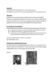
...by GIGABYTE without GIGABYTE's prior written permission. Changes to the specifications and features in the use GIGABYTE's unique features, read or download the information on/from the Support&Downloads\Motherboard\Technology Guide page on your motherboard revision before updating motherboard BIOS, ... transmitted, or published in this product, GIGABYTE provides the following types of documentations: For quick set-up of GIGABYTE. All rights reserved. For product-related information, check on our website at: http://www.gigabyte.com.tw Identifying Your Motherboard Revision The ...
...by GIGABYTE without GIGABYTE's prior written permission. Changes to the specifications and features in the use GIGABYTE's unique features, read or download the information on/from the Support&Downloads\Motherboard\Technology Guide page on your motherboard revision before updating motherboard BIOS, ... transmitted, or published in this product, GIGABYTE provides the following types of documentations: For quick set-up of GIGABYTE. All rights reserved. For product-related information, check on our website at: http://www.gigabyte.com.tw Identifying Your Motherboard Revision The ...
Manual
Page 4
Table of Contents Box Contents...6 Optional Items...6 GA-H55M-S2H Motherboard Layout 7 Block Diagram...8 Chapter 1 Hardware Installation 9 1-1 Installation Precautions 9 1-2 Product Specifications 10 1-3 Installing the CPU and CPU Cooler 13 ...1-5 Installing an Expansion Card 18 1-6 Back Panel Connectors 19 1-7 Internal Connectors 21 Chapter 2 BIOS Setup 31 2-1 Startup Screen 32 2-2 The Main Menu 33 2-3 MB Intelligent Tweaker(M.I.T 35 2-4 Standard CMOS Features 43 2-5 Advanced BIOS Features 45 2-6 Integrated Peripherals 47 2-7 Power Management Setup 50 2-8 PC Health Status 52 2-9...
Table of Contents Box Contents...6 Optional Items...6 GA-H55M-S2H Motherboard Layout 7 Block Diagram...8 Chapter 1 Hardware Installation 9 1-1 Installation Precautions 9 1-2 Product Specifications 10 1-3 Installing the CPU and CPU Cooler 13 ...1-5 Installing an Expansion Card 18 1-6 Back Panel Connectors 19 1-7 Internal Connectors 21 Chapter 2 BIOS Setup 31 2-1 Startup Screen 32 2-2 The Main Menu 33 2-3 MB Intelligent Tweaker(M.I.T 35 2-4 Standard CMOS Features 43 2-5 Advanced BIOS Features 45 2-6 Integrated Peripherals 47 2-7 Power Management Setup 50 2-8 PC Health Status 52 2-9...
Manual
Page 5
... 58 3-4 Contact...59 3-5 System...59 3-6 Download Center 60 3-7 New Utilities...60 Chapter 4 Unique Features 61 4-1 Xpress Recovery2 61 4-2 BIOS Update Utilities 64 4-2-1 Updating the BIOS with the Q-Flash Utility 64 4-2-2 Updating the BIOS with the @BIOS Utility 67 4-3 EasyTune 6...68 4-4 Dynamic Energy Saver™ 2 69 4-5 Q-Share...71 4-6 Smart 6™...72 4-7 Auto Green...75 Chapter...
... 58 3-4 Contact...59 3-5 System...59 3-6 Download Center 60 3-7 New Utilities...60 Chapter 4 Unique Features 61 4-1 Xpress Recovery2 61 4-2 BIOS Update Utilities 64 4-2-1 Updating the BIOS with the Q-Flash Utility 64 4-2-2 Updating the BIOS with the @BIOS Utility 67 4-3 EasyTune 6...68 4-4 Dynamic Energy Saver™ 2 69 4-5 Q-Share...71 4-6 Smart 6™...72 4-7 Auto Green...75 Chapter...
Manual
Page 8
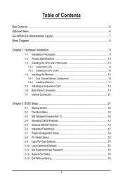
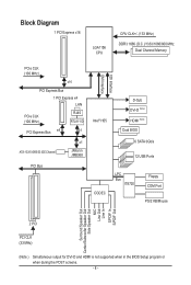
...-133/100/66/33 IDE Channel x1 JMicron JMB368 PCI Bus Intel® H55 CODEC FDI Interface DMI Interface D-Sub DVI-D (Note) HDMI (Note) Dual BIOS 6 SATA 3Gb/s 12 USB Ports LPC Bus IT8720 Floppy COM Port PS/2 KB/Mouse Surround Speaker Out Center/Subwoofer Speaker Out Side Speaker Out MIC... Out Line In S/PDIF In S/PDIF Out 2 PCI PCI CLK (33 MHz) (Note ) Simultaneous output for DVI-D and HDMI is not supported when in the BIOS Setup program or when during the POST screens. - 8 -
...-133/100/66/33 IDE Channel x1 JMicron JMB368 PCI Bus Intel® H55 CODEC FDI Interface DMI Interface D-Sub DVI-D (Note) HDMI (Note) Dual BIOS 6 SATA 3Gb/s 12 USB Ports LPC Bus IT8720 Floppy COM Port PS/2 KB/Mouse Surround Speaker Out Center/Subwoofer Speaker Out Side Speaker Out MIC... Out Line In S/PDIF In S/PDIF Out 2 PCI PCI CLK (33 MHz) (Note ) Simultaneous output for DVI-D and HDMI is not supported when in the BIOS Setup program or when during the POST screens. - 8 -
Manual
Page 12
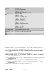
...w w w w w Bundled Software w 2 x 64 Mbit flash Use of licensed AWARD BIOS Support for DualBIOS™ PnP 1.0a, DMI 2.0, SM BIOS 2.4, ACPI 1.0b Support for @BIOS Support for Q-Flash Support for Xpress BIOS Rescue Support for Download Center Support for Xpress Install Support for Xpress Recovery2 Support for EasyTune (...does not support D-Sub connection by adapter. (Note 4) Simultaneous output for DVI-D and HDMI is not supported when in the BIOS Setup program or when during the POST screens. (Note 5) For optimum performance, if only one PCI Express graphics card is...
...w w w w w Bundled Software w 2 x 64 Mbit flash Use of licensed AWARD BIOS Support for DualBIOS™ PnP 1.0a, DMI 2.0, SM BIOS 2.4, ACPI 1.0b Support for @BIOS Support for Q-Flash Support for Xpress BIOS Rescue Support for Download Center Support for Xpress Install Support for Xpress Recovery2 Support for EasyTune (...does not support D-Sub connection by adapter. (Note 4) Simultaneous output for DVI-D and HDMI is not supported when in the BIOS Setup program or when during the POST screens. (Note 5) For optimum performance, if only one PCI Express graphics card is...
Manual
Page 16
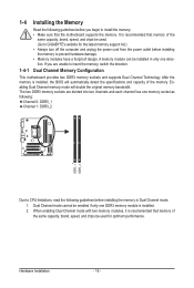
..., brand, speed, and chips be installed in only one memory socket as following: Channel 0: DDR3_1 Channel 1: DDR3_2 DDR3_1 DDR3_2 Due to GIGABYTE's website for optimum performance. It is installed, the BIOS will double the original memory bandwidth. The two DDR3 memory sockets are unable to prevent hardware damage. • Memory modules have...
..., brand, speed, and chips be installed in only one memory socket as following: Channel 0: DDR3_1 Channel 1: DDR3_2 DDR3_1 DDR3_2 Due to GIGABYTE's website for optimum performance. It is installed, the BIOS will double the original memory bandwidth. The two DDR3 memory sockets are unable to prevent hardware damage. • Memory modules have...
Manual
Page 18
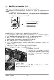
...expansion card to the chassis back panel with a screw. 5. Make sure the metal contacts on your expansion card in the slot. 3. If necessary, go to BIOS Setup to correctly install your computer. PCI Express x16 Slot (PCIEX16/PCIEX4) PCI Slot Follow the steps below to make any required... BIOS changes for your card. Turn on the card are completely inserted into the PCI Express slot. Carefully read the manual that supports your expansion card(s). 7....
...expansion card to the chassis back panel with a screw. 5. Make sure the metal contacts on your expansion card in the slot. 3. If necessary, go to BIOS Setup to correctly install your computer. PCI Express x16 Slot (PCIEX16/PCIEX4) PCI Slot Follow the steps below to make any required... BIOS changes for your card. Turn on the card are completely inserted into the PCI Express slot. Carefully read the manual that supports your expansion card(s). 7....
Manual
Page 19
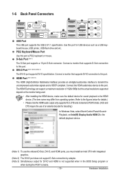
... to this port. Connect a monitor that supports DVI-D connection to this port. Refer to this port for sound playback is not supported when in the BIOS Setup program or when during the POST screens. - 19 - D-Sub Port (Note 1) The D-Sub port supports a 15-pin D-Sub connector. Connect the HDMI audio/video...
... to this port. Connect a monitor that supports DVI-D connection to this port. Refer to this port for sound playback is not supported when in the BIOS Setup program or when during the POST screens. - 19 - D-Sub Port (Note 1) The D-Sub port supports a 15-pin D-Sub connector. Connect the HDMI audio/video...
Manual
Page 20
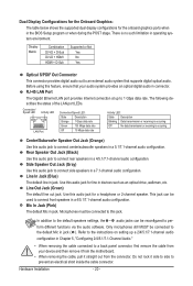
... is occurring Off No data transmission or receiving is no such limitation in a 4/5.1/7.1-channel audio configuration. Mic In Jack (Pink) The default Mic in the BIOS Setup program or when during the POST stage. Dual Display Configurations for the Onboard Graphics: The table below shows the supported dual display configurations for...
... is occurring Off No data transmission or receiving is no such limitation in a 4/5.1/7.1-channel audio configuration. Mic In Jack (Pink) The default Mic in the BIOS Setup program or when during the POST stage. Dual Display Configurations for the Onboard Graphics: The table below shows the supported dual display configurations for...
Manual
Page 25
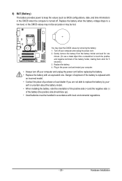
... replaced with an incorrect model. • Contact the place of purchase or local dealer if you are not able to keep the values (such as BIOS configurations, date, and time information) in the CMOS when the computer is turned off. Plug in the power cord and restart your computer. • Always...
... replaced with an incorrect model. • Contact the place of purchase or local dealer if you are not able to keep the values (such as BIOS configurations, date, and time information) in the CMOS when the computer is turned off. Plug in the power cord and restart your computer. • Always...
Manual
Page 26
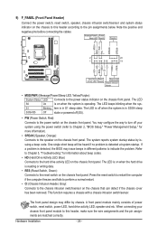
... according to the hard drive activity LED on the chassis front panel. When connecting your system using the power switch (refer to Chapter 2, "BIOS Setup," "Power Management Setup," for information about beep codes. • HD (Hard Drive Activity LED, Blue) Connects to the pin assignments below...is reading or writing data. • RES (Reset Switch, Green): Connects to the power status indicator on when the hard drive is detected, the BIOS may differ by issuing a beep code. The LED is on the chassis front panel. Hardware Installation - 26 - 9) F_PANEL (Front Panel Header) Connect...
... according to the hard drive activity LED on the chassis front panel. When connecting your system using the power switch (refer to Chapter 2, "BIOS Setup," "Power Management Setup," for information about beep codes. • HD (Hard Drive Activity LED, Blue) Connects to the pin assignments below...is reading or writing data. • RES (Reset Switch, Green): Connects to the power status indicator on when the hard drive is detected, the BIOS may differ by issuing a beep code. The LED is on the chassis front panel. Hardware Installation - 26 - 9) F_PANEL (Front Panel Header) Connect...
Manual
Page 30
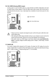
... damage to the motherboard. • After system restart, go to BIOS Setup to load factory defaults (select Load Optimized Defaults) or manually configure the BIOS settings (refer to Chapter 4, "Dynamic Energy Saver™ 2," for BIOS configurations). 17) PHASE LED The number of lighted LEDs. To enable... LED display function, please first enable Dynamic Energy Saver™ 2. The higher the CPU loading, the more details. Refer to Chapter 2, "BIOS Setup," for more the number of lighted LEDs indicates the CPU loading. Open: Normal Short: Clear CMOS Values • Always turn off your...
... damage to the motherboard. • After system restart, go to BIOS Setup to load factory defaults (select Load Optimized Defaults) or manually configure the BIOS settings (refer to Chapter 4, "Dynamic Energy Saver™ 2," for BIOS configurations). 17) PHASE LED The number of lighted LEDs. To enable... LED display function, please first enable Dynamic Energy Saver™ 2. The higher the CPU loading, the more details. Refer to Chapter 2, "BIOS Setup," for more the number of lighted LEDs indicates the CPU loading. Open: Normal Short: Clear CMOS Values • Always turn off your...

Manual
Page 31
...the power is recommended that searches and downloads the latest version of BIOS, it with caution. To see more advanced BIOS Setup menu options, you need to) to boot. To upgrade the BIOS, use either the GIGABYTE Q-Flash or @BIOS utility. • Q-Flash allows the user to keep the ...(Refer to the "Load Optimized Defaults" section in this chapter or introductions of the clearing CMOS jumper/battery in system malfunction. • BIOS will emit a beep code during system startup, saving system parameters and loading operating system, etc. Its major functions include conducting the Power-...
...the power is recommended that searches and downloads the latest version of BIOS, it with caution. To see more advanced BIOS Setup menu options, you need to) to boot. To upgrade the BIOS, use either the GIGABYTE Q-Flash or @BIOS utility. • Q-Flash allows the user to keep the ...(Refer to the "Load Optimized Defaults" section in this chapter or introductions of the clearing CMOS jumper/battery in system malfunction. • BIOS will emit a beep code during system startup, saving system parameters and loading operating system, etc. Its major functions include conducting the Power-...
Manual
Page 32
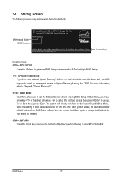
H55M-S2H E2 . . . . : BIOS Setup : XpressRecovery2 : Boot Menu : Qflash 11/16/2009-H55-7A89TG0FC-00 Function Keys Function Keys: : BIOS SETUP Press the key to enter BIOS Setup or to access the Q-Flash utility in BIOS Setup. : XPRESS RECOVERY2 If you to Xpress Recovery2 during the POST. In Boot Menu, use the ...entered Xpress Recovery2 to back up arrow key or the down arrow key to select the first boot device, then press to enter BIOS Setup first. BIOS Setup - 32 - After system restart, the device boot order will directly boot from the device configured in Boot Menu is effective...
H55M-S2H E2 . . . . : BIOS Setup : XpressRecovery2 : Boot Menu : Qflash 11/16/2009-H55-7A89TG0FC-00 Function Keys Function Keys: : BIOS SETUP Press the key to enter BIOS Setup or to access the Q-Flash utility in BIOS Setup. : XPRESS RECOVERY2 If you to Xpress Recovery2 during the POST. In Boot Menu, use the ...entered Xpress Recovery2 to back up arrow key or the down arrow key to select the first boot device, then press to enter BIOS Setup first. BIOS Setup - 32 - After system restart, the device boot order will directly boot from the device configured in Boot Menu is effective...
Manual
Page 33
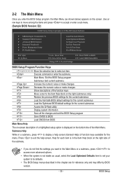
... & Exit Setup Exit Without Saving Select Item F10: Save & Exit Setup Change CPU's Clock & Voltage F11: Save CMOS to BIOS F12: Load CMOS from BIOS BIOS Setup Program Function Keys Move the selection bar to select an item Execute command or enter the submenu Main Menu: Exit the... settings for the current submenus Access the Q-Flash utility Display system information Save all the changes and exit the BIOS Setup program Save CMOS to BIOS Load CMOS from BIOS Main Menu Help The on-screen description of a highlighted setup option is displayed on the bottom line of the...
... & Exit Setup Exit Without Saving Select Item F10: Save & Exit Setup Change CPU's Clock & Voltage F11: Save CMOS to BIOS F12: Load CMOS from BIOS BIOS Setup Program Function Keys Move the selection bar to select an item Execute command or enter the submenu Main Menu: Exit the... settings for the current submenus Access the Q-Flash utility Display system information Save all the changes and exit the BIOS Setup program Save CMOS to BIOS Load CMOS from BIOS Main Menu Help The on-screen description of a highlighted setup option is displayed on the bottom line of the...
Manual
Page 34
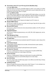
...time and date, hard drive types, floppy disk drive types, and the type of errors that stop the system boot, etc. Advanced BIOS Features Use this menu to configure the device boot order, advanced features available on the CPU, and the primary display adapter. Integrated Peripherals...LAN, etc. Power Management Setup Use this menu to configure all changes and the previous settings remain in the BIOS Setup program to the CMOS and exit BIOS Setup. (Pressing can also carry out this menu to see information about autodetected system/CPU temperature, system voltage and fan...
...time and date, hard drive types, floppy disk drive types, and the type of errors that stop the system boot, etc. Advanced BIOS Features Use this menu to configure the device boot order, advanced features available on the CPU, and the primary display adapter. Integrated Peripherals...LAN, etc. Power Management Setup Use this menu to configure all changes and the previous settings remain in the BIOS Setup program to the CMOS and exit BIOS Setup. (Pressing can also carry out this menu to see information about autodetected system/CPU temperature, system voltage and fan...
Manual
Page 35
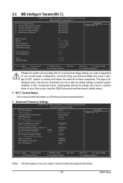
... Settings } Miscellaneous Settings [Press Enter] [Press Enter] [Press Enter] [Press Enter] [Press Enter] Item Help Menu Level BIOS Version BCLK CPU Frequency Memory Frequency Total Memory Size CPU Temperature PCH Temperature Vcore DRAM Voltage E2 133.27 MHz 3198.42 MHz 1332.80... for advanced users only and we recommend you install a memory module that supports this feature. - 35 - BIOS Setup 2-3 MB Intelligent Tweaker(M.I.T.) CMOS Setup Utility-Copyright (C) 1984-2009 Award Software MB Intelligent Tweaker(M.I.T.) } M.I .T.
... Settings } Miscellaneous Settings [Press Enter] [Press Enter] [Press Enter] [Press Enter] [Press Enter] Item Help Menu Level BIOS Version BCLK CPU Frequency Memory Frequency Total Memory Size CPU Temperature PCH Temperature Vcore DRAM Voltage E2 133.27 MHz 3198.42 MHz 1332.80... for advanced users only and we recommend you install a memory module that supports this feature. - 35 - BIOS Setup 2-3 MB Intelligent Tweaker(M.I.T.) CMOS Setup Utility-Copyright (C) 1984-2009 Award Software MB Intelligent Tweaker(M.I.T.) } M.I .T.
Manual
Page 36
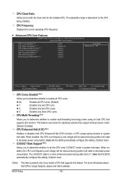
...1 Enables only one CPU core. 2 Enables only two CPU cores. 3 Enables only three CPU cores. BIOS Setup - 36 - This feature only works for the installed CPU. Auto lets the BIOS automatically configure this setting. (Default: Auto) C3/C6/C7 State Support (Note) Allows you to determine ... Multi-Threading (Note) Allows you to determine whether to alter the clock ratio for operating systems that supports this feature. Auto lets the BIOS automatically configure this setting. (Default: Auto) (Note) This item is dependent on the CPU being installed. All Enables all CPU cores...
...1 Enables only one CPU core. 2 Enables only two CPU cores. 3 Enables only three CPU cores. BIOS Setup - 36 - This feature only works for the installed CPU. Auto lets the BIOS automatically configure this setting. (Default: Auto) C3/C6/C7 State Support (Note) Allows you to determine ... Multi-Threading (Note) Allows you to determine whether to alter the clock ratio for operating systems that supports this feature. Auto lets the BIOS automatically configure this setting. (Default: Auto) (Note) This item is dependent on the CPU being installed. All Enables all CPU cores...
Manual
Page 37
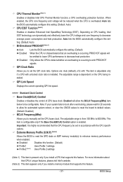
...overheating is from 100 MHz to decrease heat production. The item is adjustable only if a CPU with the CPU specifications. BIOS Setup Depending on the CPU being installed. QPI Link Speed Displays the current operating QPI link speed. >>>>> Standard Clock Control ... consumption and heat production. Auto lets the BIOS automatically configure this function. (Default) Profile1 Uses Profile 1 settings. Auto lets the BIOS automatically configure this setting. (Default: Auto) Bi-Directional PROCHOT (Note 1) Auto Lets the BIOS automatically configure this setting. (Default) Enabled...
...overheating is from 100 MHz to decrease heat production. The item is adjustable only if a CPU with the CPU specifications. BIOS Setup Depending on the CPU being installed. QPI Link Speed Displays the current operating QPI link speed. >>>>> Standard Clock Control ... consumption and heat production. Auto lets the BIOS automatically configure this function. (Default) Profile1 Uses Profile 1 settings. Auto lets the BIOS automatically configure this setting. (Default: Auto) Bi-Directional PROCHOT (Note 1) Auto Lets the BIOS automatically configure this setting. (Default) Enabled...
Manual
Page 38
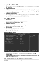
.... the second is automatically adjusted according to adjust the amplitude of the CPU and the Chipset clock. Auto sets memory multiplier according to 150 MHz. BIOS Setup - 38 - PCI Express Frequency(Mhz) Allows you to manually set the CPU clock prior to set the system memory multiplier. System Memory Multiplier (SPD...
.... the second is automatically adjusted according to adjust the amplitude of the CPU and the Chipset clock. Auto sets memory multiplier according to 150 MHz. BIOS Setup - 38 - PCI Express Frequency(Mhz) Allows you to manually set the CPU clock prior to set the system memory multiplier. System Memory Multiplier (SPD...


