Manual
Page 3
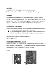
...product information, carefully read the User's Manual. For instructions on how to use of this manual may be made by GIGABYTE without GIGABYTE's prior written permission. Documentation Classifications In order to their respective owners. Copyright © 2010 GIGA-BYTE TECHNOLOGY CO., LTD. ... download the information on/from the Support&Downloads\Motherboard\Technology Guide page on your motherboard revision before updating motherboard BIOS, drivers, or when looking for technical information. All rights reserved. Check your motherboard looks like this manual...
...product information, carefully read the User's Manual. For instructions on how to use of this manual may be made by GIGABYTE without GIGABYTE's prior written permission. Documentation Classifications In order to their respective owners. Copyright © 2010 GIGA-BYTE TECHNOLOGY CO., LTD. ... download the information on/from the Support&Downloads\Motherboard\Technology Guide page on your motherboard revision before updating motherboard BIOS, drivers, or when looking for technical information. All rights reserved. Check your motherboard looks like this manual...
Manual
Page 4
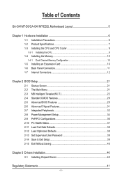
Table of Contents GA-G41MT-D3/GA-G41MT-ES2L Motherboard Layout 5 Chapter 1 Hardware Installation 6 1-1 Installation Precautions 6 1-2 Product Specifications 7 1-3 Installing the CPU and CPU Cooler 9 1-3-1 Installing the CPU...9 1-4 Installing the Memory 10 1-4-1 Dual Channel Memory Configuration 10 1-5 Installing an Expansion Card 10 1-6 Back Panel Connectors 11 1-7 Internal Connectors 12 Chapter 2 BIOS Setup 21 2-1 Startup Screen 21 2-2 The Main...
Table of Contents GA-G41MT-D3/GA-G41MT-ES2L Motherboard Layout 5 Chapter 1 Hardware Installation 6 1-1 Installation Precautions 6 1-2 Product Specifications 7 1-3 Installing the CPU and CPU Cooler 9 1-3-1 Installing the CPU...9 1-4 Installing the Memory 10 1-4-1 Dual Channel Memory Configuration 10 1-5 Installing an Expansion Card 10 1-6 Back Panel Connectors 11 1-7 Internal Connectors 12 Chapter 2 BIOS Setup 21 2-1 Startup Screen 21 2-2 The Main...
Manual
Page 8
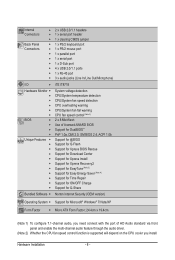
... w 1 x PS/2 mouse port w 1 x parallel port w 1 x serial port w 1 x D-Sub port w 4 x USB 2.0/1.1 ports w 1 x RJ-45 port w 3 x audio jacks (Line In/Line Out/Microphone) I/O w iTE IT8718 Hardware Monitor w w w w w w BIOS w w w w Unique Features w w w w w w w w w w w System voltage detection CPU/System temperature detection CPU/System fan speed detection CPU overheating warning CPU/System fan fail warning CPU fan speed...
... w 1 x PS/2 mouse port w 1 x parallel port w 1 x serial port w 1 x D-Sub port w 4 x USB 2.0/1.1 ports w 1 x RJ-45 port w 3 x audio jacks (Line In/Line Out/Microphone) I/O w iTE IT8718 Hardware Monitor w w w w w w BIOS w w w w Unique Features w w w w w w w w w w w System voltage detection CPU/System temperature detection CPU/System fan speed detection CPU overheating warning CPU/System fan fail warning CPU fan speed...
Manual
Page 10
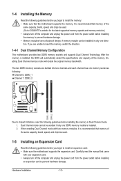
.... • Memory modules have a foolproof design. After the memory is recommended that memory of the same capacity, brand, speed, and chips be used . (Go to GIGABYTE's website for the latest supported memory speeds and memory modules.) • Always turn off the computer and unplug the power cord from the power outlet... memory socket as following guidelines before you begin to install the memory: • Make sure that came with two memory modules, it is installed, the BIOS will double the original memory bandwidth.
.... • Memory modules have a foolproof design. After the memory is recommended that memory of the same capacity, brand, speed, and chips be used . (Go to GIGABYTE's website for the latest supported memory speeds and memory modules.) • Always turn off the computer and unplug the power cord from the power outlet... memory socket as following guidelines before you begin to install the memory: • Make sure that came with two memory modules, it is installed, the BIOS will double the original memory bandwidth.
Manual
Page 16
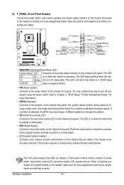
... removed. This function requires a chassis with a chassis intrusion switch/sensor. When connecting your system using the power switch (refer to Chapter 2, "BIOS Setup," "Power Management Setup," for more information). • SPEAK (Speaker): Connects to the speaker on the chassis front panel. SPEAK+ PWPW+...indicate the problem. • HD (Hard Drive Activity LED) Connects to the power status indicator on when the system is detected, the BIOS may differ by issuing a beep code. Hardware Installation - 16 - A front panel module mainly consists of power switch, reset switch, ...
... removed. This function requires a chassis with a chassis intrusion switch/sensor. When connecting your system using the power switch (refer to Chapter 2, "BIOS Setup," "Power Management Setup," for more information). • SPEAK (Speaker): Connects to the speaker on the chassis front panel. SPEAK+ PWPW+...indicate the problem. • HD (Hard Drive Activity LED) Connects to the power status indicator on when the system is detected, the BIOS may differ by issuing a beep code. Hardware Installation - 16 - A front panel module mainly consists of power switch, reset switch, ...
Manual
Page 19
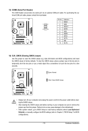
... the motherboard. • After system restart, go to BIOS Setup to load factory defaults (select Load Optimized Defaults) or manually configure the BIOS settings (refer to factory defaults. date information and BIOS configurations) and reset the CMOS values to Chapter 2, "BIOS Setup," for a few seconds. To clear the CMOS values..., place a jumper cap on your computer, be sure to touch the two pins for BIOS configurations). - 19 - Open: Normal Short: Clear CMOS Values • Always turn off your computer and unplug the power cord from the ...
... the motherboard. • After system restart, go to BIOS Setup to load factory defaults (select Load Optimized Defaults) or manually configure the BIOS settings (refer to factory defaults. date information and BIOS configurations) and reset the CMOS values to Chapter 2, "BIOS Setup," for a few seconds. To clear the CMOS values..., place a jumper cap on your computer, be sure to touch the two pins for BIOS configurations). - 19 - Open: Normal Short: Clear CMOS Values • Always turn off your computer and unplug the power cord from the ...
Manual
Page 20
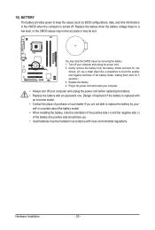
... the battery from the battery holder and wait for 5 seconds.) 3. Hardware Installation - 20 - 15) BATTERY The battery provides power to keep the values (such as BIOS configurations, date, and time information) in the CMOS when the computer is replaced with an incorrect model. • Contact the place of purchase or local...
... the battery from the battery holder and wait for 5 seconds.) 3. Hardware Installation - 20 - 15) BATTERY The battery provides power to keep the values (such as BIOS configurations, date, and time information) in the CMOS when the computer is replaced with an incorrect model. • Contact the place of purchase or local...
Manual
Page 21
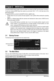
... screens may result in the main menu of BIOS, it with caution. To upgrade the BIOS, use either the GIGABYTE Q-Flash or @BIOS utility. • Q-Flash allows the user to boot. Motherboard Model BIOS Version Award Modular BIOS v6.00PG, An Energy Star Ally Copyright (C)... and press to accept or enter a sub-menu. (Sample BIOS Version: GA-G41MT-D3 E7c) CMOS Setup Utility-Copyright (C) 1984-2010 Award Software MB Intelligent Tweaker(M.I.T.) Standard CMOS Features Advanced BIOS Features Advanced Chipset Features Integrated Peripherals ...
... screens may result in the main menu of BIOS, it with caution. To upgrade the BIOS, use either the GIGABYTE Q-Flash or @BIOS utility. • Q-Flash allows the user to boot. Motherboard Model BIOS Version Award Modular BIOS v6.00PG, An Energy Star Ally Copyright (C)... and press to accept or enter a sub-menu. (Sample BIOS Version: GA-G41MT-D3 E7c) CMOS Setup Utility-Copyright (C) 1984-2010 Award Software MB Intelligent Tweaker(M.I.T.) Standard CMOS Features Advanced BIOS Features Advanced Chipset Features Integrated Peripherals ...
Manual
Page 22
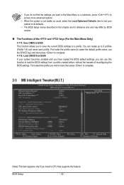
... created before, without the hassles of the and keys (For the Main Menu Only) F11: Save CMOS to BIOS This function allows you to save the current BIOS settings to a profile. BIOS Setup - 22 - First enter the profile name (to erase the default profile name, use this function to load the... BIOS settings from BIOS If your system to its defaults. • The BIOS Setup menus described in the Main Menu or a submenu, press + to access more advanced options. • When the system ...
... created before, without the hassles of the and keys (For the Main Menu Only) F11: Save CMOS to BIOS This function allows you to save the current BIOS settings to a profile. BIOS Setup - 22 - First enter the profile name (to erase the default profile name, use this function to load the... BIOS settings from BIOS If your system to its defaults. • The BIOS Setup menus described in the Main Menu or a submenu, press + to access more advanced options. • When the system ...

Manual
Page 23
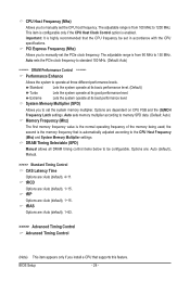
...clear the CMOS values and reset the board to default values.) Robust Graphics Booster Robust Graphics Booster (R.G.B.) helps to boot. Auto allows the BIOS to be configurable. Incorrectly doing overclock/overvoltage may result in damage to CPU, chipset, or memory and reduce the useful life of CPU ...host clock. BIOS Setup This page is for the installed CPU. The item is present only if a CPU with unlocked clock ratio is installed. Fine ...
...clear the CMOS values and reset the board to default values.) Robust Graphics Booster Robust Graphics Booster (R.G.B.) helps to boot. Auto allows the BIOS to be configurable. Incorrectly doing overclock/overvoltage may result in damage to CPU, chipset, or memory and reduce the useful life of CPU ...host clock. BIOS Setup This page is for the installed CPU. The item is present only if a CPU with unlocked clock ratio is installed. Fine ...
Manual
Page 24
... at three different performance levels. tRCD Options are : Auto (default), 1~15. the second is the memory frequency that is highly recommended that supports this feature. BIOS Setup - 24 - Important: It is automatically adjusted according to manually set the PCIe clock frequency. CPU Host Frequency (Mhz) Allows you to the CPU Host...
... at three different performance levels. tRCD Options are : Auto (default), 1~15. the second is the memory frequency that is highly recommended that supports this feature. BIOS Setup - 24 - Important: It is automatically adjusted according to manually set the PCIe clock frequency. CPU Host Frequency (Mhz) Allows you to the CPU Host...
Manual
Page 25
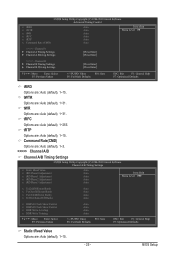
tRFC Options are : Auto (default), 1~15. tRTP Options are : Auto (default), 1~255. BIOS Setup tWR Options are : Auto (default), 1~15. CMOS Setup Utility-Copyright (C) 1984-2010 Award Software Advanced Timing Control x tRRD x tWTR x tWR x tRFC x tRTP x Command Rate (...
tRFC Options are : Auto (default), 1~15. tRTP Options are : Auto (default), 1~255. BIOS Setup tWR Options are : Auto (default), 1~15. CMOS Setup Utility-Copyright (C) 1984-2010 Award Software Advanced Timing Control x tRRD x tWTR x tWR x tRFC x tRTP x Command Rate (...
Manual
Page 26
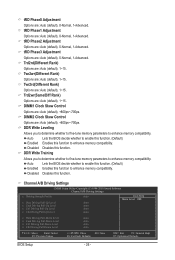
... Auto (default), +800ps~-700ps. DIMM1 Clock Skew Control Options are : Auto (default), 0-Normal, 1-Advanced. Auto Lets the BIOS decide whether to enable this function. (Default) Enabled Enables this function to enhance memory compatibility. Channel A/B Driving Settings CMOS Setup Utility... fine-tune memory parameters to enhance memory compatibility. tRD Phase2 Adjustment Options are : Auto (default), 1~15. Auto Lets the BIOS decide whether to enable this function. (Default) Enabled Enables this function to enhance memory compatibility. Twr2wr(Different Rank) Options are ...
... Auto (default), +800ps~-700ps. DIMM1 Clock Skew Control Options are : Auto (default), 0-Normal, 1-Advanced. Auto Lets the BIOS decide whether to enable this function. (Default) Enabled Enables this function to enhance memory compatibility. Channel A/B Driving Settings CMOS Setup Utility... fine-tune memory parameters to enhance memory compatibility. tRD Phase2 Adjustment Options are : Auto (default), 1~15. Auto Lets the BIOS decide whether to enable this function. (Default) Enabled Enables this function to enhance memory compatibility. Twr2wr(Different Rank) Options are ...
Manual
Page 27
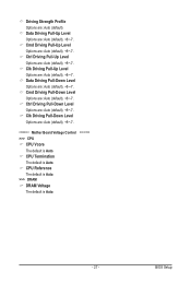
... Options are : Auto (default). CPU Reference The default is Auto. >>> DRAM DRAM Voltage The default is Auto. - 27 - Driving Strength Profile Options are : Auto (default), +8~-7. BIOS Setup
... Options are : Auto (default). CPU Reference The default is Auto. >>> DRAM DRAM Voltage The default is Auto. - 27 - Driving Strength Profile Options are : Auto (default), +8~-7. BIOS Setup
Manual
Page 28
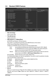
... Master/Slave, Extended IDE Drive Configure your IDE/SATA devices by using one of the three methods below: • Auto Lets the BIOS automatically detect IDE/SATA devices during the POST for faster system startup. • Manual Allows you to select the type of the hard...Time (hh:mm:ss) Sets the system time. Sector Number of the IDE/SATA device on the hard drive. Cylinder Number of heads. BIOS Setup - 28 - Landing Zone Landing zone. Head Number of cylinders. Capacity Approximate capacity of the currently installed hard drive. Options are used...
... Master/Slave, Extended IDE Drive Configure your IDE/SATA devices by using one of the three methods below: • Auto Lets the BIOS automatically detect IDE/SATA devices during the POST for faster system startup. • Manual Allows you to select the type of the hard...Time (hh:mm:ss) Sets the system time. Sector Number of the IDE/SATA device on the hard drive. Cylinder Number of heads. BIOS Setup - 28 - Landing Zone Landing zone. Head Number of cylinders. Capacity Approximate capacity of the currently installed hard drive. Options are used...
Manual
Page 29
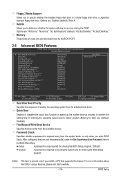
... more information about Intel CPUs' unique features, please visit Intel's website. - 29 - Setup A password is only required for entering the BIOS Setup program. (Default) System A password is 3-mode floppy disk drive, a Japanese standard floppy disk drive. Password Check Specifies whether a ...password is present only if you enter BIOS Setup. After configuring this feature. Options are: Disabled (default), Drive A. Quick Boot Enables or disables the quick boot function to ...
... more information about Intel CPUs' unique features, please visit Intel's website. - 29 - Setup A password is only required for entering the BIOS Setup program. (Default) System A password is 3-mode floppy disk drive, a Japanese standard floppy disk drive. Password Check Specifies whether a ...password is present only if you enter BIOS Setup. After configuring this feature. Options are: Disabled (default), Drive A. Quick Boot Enables or disables the quick boot function to ...
Manual
Page 30
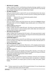
... Enhanced Halt (C1E) (Note) Enables or disables Intel CPU Enhanced Halt (C1E) function, a CPU power-saving function in system halt state. Limit CPUID Max. HDD S.M.A.R.T. BIOS Setup - 30 - Virtualization enhanced by Intel Virtualization Technology will be reduced during system halt state to decrease power consumption. (Default: Enabled) C2/C2E State Support...
... Enhanced Halt (C1E) (Note) Enables or disables Intel CPU Enhanced Halt (C1E) function, a CPU power-saving function in system halt state. Limit CPUID Max. HDD S.M.A.R.T. BIOS Setup - 30 - Virtualization enhanced by Intel Virtualization Technology will be reduced during system halt state to decrease power consumption. (Default: Enabled) C2/C2E State Support...
Manual
Page 31
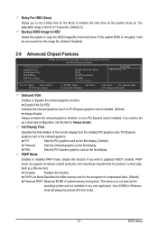
...you to set this item to initialize the hard drive as the system boots up a dual view configuration, set a delay time for the BIOS to Always Enable. Enable If No Ext PEG Activates the onboard graphics only if no PCI Express graphics card is installed. (Default) Always... Specifies the buffer memory size for premium content playback (e.g. PAVP Mode Enables or disables PAVP mode. Disabled Disables this mode. - 31 - BIOS Setup PCI Sets the PCI graphics card as the first display. (Default) Onboard Sets the onboard graphics as the first display. This memory is...
...you to set this item to initialize the hard drive as the system boots up a dual view configuration, set a delay time for the BIOS to Always Enable. Enable If No Ext PEG Activates the onboard graphics only if no PCI Express graphics card is installed. (Default) Always... Specifies the buffer memory size for premium content playback (e.g. PAVP Mode Enables or disables PAVP mode. Disabled Disables this mode. - 31 - BIOS Setup PCI Sets the PCI graphics card as the first display. (Default) Onboard Sets the onboard graphics as the first display. This memory is...
Manual
Page 32
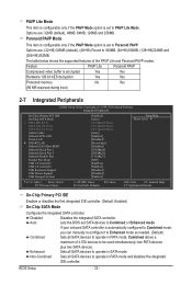
.... PAVP Lite Mode This item is configurable only if the PAVP Mode option is set SATA devices to Combined or Enhanced mode. BIOS Setup - 32 - Auto Lets the BIOS set to PAVP Lite Mode. Paranoid PAVP Mode This item is configurable only if the PAVP Mode option is encrypted Yes Yes Hardware...
.... PAVP Lite Mode This item is configurable only if the PAVP Mode option is set SATA devices to Combined or Enhanced mode. BIOS Setup - 32 - Auto Lets the BIOS set to PAVP Lite Mode. Paranoid PAVP Mode This item is configurable only if the PAVP Mode option is encrypted Yes Yes Hardware...

Manual
Page 33
... IDE channels to Disabled. PATA IDE Set to This item is configurable only if the On-Chip SATA Mode is set to Ch. 1 Master/Slave. BIOS Setup Green LAN When the onboard LAN function and Green LAN are enabled, the system will be automatically set to Combined. When PATA IDE Set...
... IDE channels to Disabled. PATA IDE Set to This item is configurable only if the On-Chip SATA Mode is set to Ch. 1 Master/Slave. BIOS Setup Green LAN When the onboard LAN function and Green LAN are enabled, the system will be automatically set to Combined. When PATA IDE Set...


