
Manual
Page 2
Installing the Smart TPM Utility 4 3. Initializing the TPM Chip with the Smart TPM Utility 5 3.2. Creating a Bluetooth Cell Phone Key 19 4.3. Installing the Infineon TPM Driver and the Smart TPM Utility 4 2.1. Installing the Infineon TPM Driver 4 2.2. Advanced Mode...8 4. Other Bluetooth Settings 21 4.4. Creating a USB Key 18 4.2. Initializing the TPM chip 5 3.1. Configuring the Smart TPM Utility 18 4.1. Other Features...21 - 2 - Table of Contents TPM Configuration Procedure 3 1. Configuring the System BIOS 3 2.
Installing the Smart TPM Utility 4 3. Initializing the TPM Chip with the Smart TPM Utility 5 3.2. Creating a Bluetooth Cell Phone Key 19 4.3. Installing the Infineon TPM Driver and the Smart TPM Utility 4 2.1. Installing the Infineon TPM Driver 4 2.2. Advanced Mode...8 4. Other Bluetooth Settings 21 4.4. Creating a USB Key 18 4.2. Initializing the TPM chip 5 3.1. Configuring the Smart TPM Utility 18 4.1. Other Features...21 - 2 - Table of Contents TPM Configuration Procedure 3 1. Configuring the System BIOS 3 2.

Manual
Page 3
...2: After completing the settings, press to back up the encrypted files first. Initializing the TPM chip 4. Configuring the System BIOS To use the Clear Security Chip setting (press + in the BIOS main menu to display this setting) to activate the TPM chip. Step 1: As the computer starts, enter the... BIOS Setup program. To activate the TPM chip, set the User Password in sequence: 1. Be sure to save changes and then exit the BIOS Setup program. It's recommended that you use the TPM functionality, first enter ...
...2: After completing the settings, press to back up the encrypted files first. Initializing the TPM chip 4. Configuring the System BIOS To use the Clear Security Chip setting (press + in the BIOS main menu to display this setting) to activate the TPM chip. Step 1: As the computer starts, enter the... BIOS Setup program. To activate the TPM chip, set the User Password in sequence: 1. Be sure to save changes and then exit the BIOS Setup program. It's recommended that you use the TPM functionality, first enter ...

Manual
Page 5
... the PSD drive letter, drive label, size, and a local drive on which indicates that is automatically provided. Initializing the TPM chip After configuring the system BIOS and installing the driver software, the Infineon Security Platform icon , which your own password. The Smart TPM Interface Set Your TPM Password A password is configured...
... the PSD drive letter, drive label, size, and a local drive on which indicates that is automatically provided. Initializing the TPM chip After configuring the system BIOS and installing the driver software, the Infineon Security Platform icon , which your own password. The Smart TPM Interface Set Your TPM Password A password is configured...

Manual
Page 6
... Your TPM User Password 1. The maximum PSD drive size on FAT16 volumes is 2 GB. Please note that you cannot use the Security Platform in the BIOS Setup program. • This password incorporates the functionalities of the "Owner Password," "User Password," "Emergency Recovery Token Password," and "Password Reset Token Password" of the...
... Your TPM User Password 1. The maximum PSD drive size on FAT16 volumes is 2 GB. Please note that you cannot use the Security Platform in the BIOS Setup program. • This password incorporates the functionalities of the "Owner Password," "User Password," "Emergency Recovery Token Password," and "Password Reset Token Password" of the...

Manual
Page 7
...stores their encrypted TPM User Passwords in . Selecting the Enable Backup to search for pairing. Enter a passkey (8~16 digits recommended) in the system BIOS. Then enter the same passkey on the left will store the encrypted TPM User Password in Passkey which will overwrite the former. 2. Create a... Bluetooth cell phone key: Select the Use Bluetooth Device check box and click Refresh to BIOS check box will appear. Then select the USB flash drive that on your cell phone. Create a USB key: Select the Use USB storage...
...stores their encrypted TPM User Passwords in . Selecting the Enable Backup to search for pairing. Enter a passkey (8~16 digits recommended) in the system BIOS. Then enter the same passkey on the left will store the encrypted TPM User Password in Passkey which will overwrite the former. 2. Create a... Bluetooth cell phone key: Select the Use Bluetooth Device check box and click Refresh to BIOS check box will appear. Then select the USB flash drive that on your cell phone. Create a USB key: Select the Use USB storage...

Manual
Page 18
... liable for loss of complicated configurations. Configuring the Smart TPM Utility GIGABYTE's unique Smart TPM (Trusted Platform Module) supports the industry's most advanced ...TPM chip and setting up . In addition, users can create more than one user uses the "Enable Bacup to BIOS" function to store their PSD data by simply connecting to create a portable user key using a Bluetooth cell phone or... so when they lost a key they still can access/close their encrypted TPM User Passwords in the BIOS, the latter will render the files encrypted via the TPM unable to be sure to store them in...
... liable for loss of complicated configurations. Configuring the Smart TPM Utility GIGABYTE's unique Smart TPM (Trusted Platform Module) supports the industry's most advanced ...TPM chip and setting up . In addition, users can create more than one user uses the "Enable Bacup to BIOS" function to store their PSD data by simply connecting to create a portable user key using a Bluetooth cell phone or... so when they lost a key they still can access/close their encrypted TPM User Passwords in the BIOS, the latter will render the files encrypted via the TPM unable to be sure to store them in...

Manual
Page 19
... you set "Security Chip" to "Enabled/Activate." • When you want to use as the Smart TPM user key on your PSD by plugging in BIOS Setup and then set earlier and click OK to complete creating the USB key. Step 3: Enter the TPM User Password that has been configured as...
... you set "Security Chip" to "Enabled/Activate." • When you want to use as the Smart TPM user key on your PSD by plugging in BIOS Setup and then set earlier and click OK to complete creating the USB key. Step 3: Enter the TPM User Password that has been configured as...
Manual
Page 3
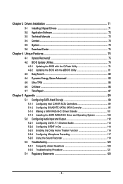
... or download the information on/from the Support\Motherboard\Technology Guide page on your motherboard revision before updating motherboard BIOS, drivers, or when looking for technical information. Disclaimer Information in any means without prior notice. Changes to ...their respective owners. Documentation Classifications In order to assist in this product, GIGABYTE provides the following types of documentations: For quick set-up of this manual may be reproduced, copied, translated, transmitted,...
... or download the information on/from the Support\Motherboard\Technology Guide page on your motherboard revision before updating motherboard BIOS, drivers, or when looking for technical information. Disclaimer Information in any means without prior notice. Changes to ...their respective owners. Documentation Classifications In order to assist in this product, GIGABYTE provides the following types of documentations: For quick set-up of this manual may be reproduced, copied, translated, transmitted,...

Manual
Page 4
Table of Contents Box Contents ...6 OptionalItems ...6 GA-EX58-UD4P Motherboard Layout 7 Block Diagram ...8 Chapter 1 Hardware Installation 9 1-1 Installation Precautions 9 1-2 Product Specifications 10 1-3 Installing the CPU and CPU Cooler 13 1-3-1... Panel Connectors 23 1-9 Onboard LEDs and Switches 25 1-10 Internal Connectors 27 Chapter 2 BIOS Setup 41 2-1 Startup Screen 42 2-2 The Main Menu 43 2-3 MB Intelligent Tweaker(M.I.T 45 2-4 Standard CMOS Features 55 2-5 Advanced BIOS Features 57 2-6 IntegratedPeripherals 59 2-7 Power Management Setup 62 2-8 PC Health Status 64 2-9...
Table of Contents Box Contents ...6 OptionalItems ...6 GA-EX58-UD4P Motherboard Layout 7 Block Diagram ...8 Chapter 1 Hardware Installation 9 1-1 Installation Precautions 9 1-2 Product Specifications 10 1-3 Installing the CPU and CPU Cooler 13 1-3-1... Panel Connectors 23 1-9 Onboard LEDs and Switches 25 1-10 Internal Connectors 27 Chapter 2 BIOS Setup 41 2-1 Startup Screen 42 2-2 The Main Menu 43 2-3 MB Intelligent Tweaker(M.I.T 45 2-4 Standard CMOS Features 55 2-5 Advanced BIOS Features 57 2-6 IntegratedPeripherals 59 2-7 Power Management Setup 62 2-8 PC Health Status 64 2-9...
Manual
Page 5
...Center 74 Chapter 4 Unique Features 75 4-1 Xpress Recovery2 75 4-2 BIOS Update Utilities 78 4-2-1 Updating the BIOS with the Q-Flash Utility 78 4-2-2 Updating the BIOS with the @BIOS Utility 81 4-3 EasyTune 6 ...82 4-4 Dynamic Energy Saver Advanced... 83 4-5 Ultra TPM ...85 4-6 Q-Share ...86 4-7 Time Repair ...87 Chapter 5 Appendix ...89 5-1 Configuring SATA Hard Drive(s 89 5-1-1 Configuring Intel ICH10R SATA Controllers 89 5-1-2 Configuring GIGABYTE...
...Center 74 Chapter 4 Unique Features 75 4-1 Xpress Recovery2 75 4-2 BIOS Update Utilities 78 4-2-1 Updating the BIOS with the Q-Flash Utility 78 4-2-2 Updating the BIOS with the @BIOS Utility 81 4-3 EasyTune 6 ...82 4-4 Dynamic Energy Saver Advanced... 83 4-5 Ultra TPM ...85 4-6 Q-Share ...86 4-7 Time Repair ...87 Chapter 5 Appendix ...89 5-1 Configuring SATA Hard Drive(s 89 5-1-1 Configuring Intel ICH10R SATA Controllers 89 5-1-2 Configuring GIGABYTE...

Manual
Page 8
... Switch x4 x16 PCI Express Bus 1 PCI Express x1 PCI CLK (33 MHz) x1 LAN1 RJ45 RTL 8111D x1 PCI Express Bus 2 SATA 3Gb/s x1 GIGABYTE SATA2 ATA-133/100/66/33 IDE Channel PCI Bus TSB43AB23 QPI Interface Intel® X58 IOH CLK (133 MHz) Intel® ICH10R Dual... BIOS 6 SATA 3Gb/s 12 USB Ports CODEC LPC Bus IT8720 Floppy PS/2 KB/Mouse 3 IEEE 1394a TPM Surround Speaker Out Center/Subwoofer Speaker Out Side Speaker ...
... Switch x4 x16 PCI Express Bus 1 PCI Express x1 PCI CLK (33 MHz) x1 LAN1 RJ45 RTL 8111D x1 PCI Express Bus 2 SATA 3Gb/s x1 GIGABYTE SATA2 ATA-133/100/66/33 IDE Channel PCI Bus TSB43AB23 QPI Interface Intel® X58 IOH CLK (133 MHz) Intel® ICH10R Dual... BIOS 6 SATA 3Gb/s 12 USB Ports CODEC LPC Bus IT8720 Floppy PS/2 KB/Mouse 3 IEEE 1394a TPM Surround Speaker Out Center/Subwoofer Speaker Out Side Speaker ...

Manual
Page 12
...in EasyTune may differ by motherboard model. GA-EX58-UD4P Motherboard - 12 - When PCIEX8_1 is populated with the PCIEX16_2 slot. BIOS Unique Features Bundled Software Operating System Form Factor 2 x 8 Mbit flash Use of licensed AWARD BIOS Support for DualBIOSTM PnP... 1.0a, DMI 2.0, SM BIOS 2.4, ACPI 1.0b Support for @BIOS Support for Q-Flash Support for Virtual Dual BIOS Support for Download Center Support for ...
...in EasyTune may differ by motherboard model. GA-EX58-UD4P Motherboard - 12 - When PCIEX8_1 is populated with the PCIEX16_2 slot. BIOS Unique Features Bundled Software Operating System Form Factor 2 x 8 Mbit flash Use of licensed AWARD BIOS Support for DualBIOSTM PnP... 1.0a, DMI 2.0, SM BIOS 2.4, ACPI 1.0b Support for @BIOS Support for Q-Flash Support for Virtual Dual BIOS Support for Download Center Support for ...

Manual
Page 16
... A memory module can be enabled if only one DDR3 memory module is installed, the BIOS will appear during the POST. Dual or 3 Channel memory mode may double or triple ... mode cannot be installed in the DDR3_1, DDR3_2, DDR3_3 and DDR3_5 sockets. • If only one direction. GA-EX58-UD4P Motherboard - 16 - When enabling Dual Channel mode with three memory modules, be sure to chipset limitation, read...that memory of the same capacity, brand, speed, and chips be used . (Go to GIGABYTE's website for the latest memory support list.) • Always turn off the computer and unplug...
... A memory module can be enabled if only one DDR3 memory module is installed, the BIOS will appear during the POST. Dual or 3 Channel memory mode may double or triple ... mode cannot be installed in the DDR3_1, DDR3_2, DDR3_3 and DDR3_5 sockets. • If only one direction. GA-EX58-UD4P Motherboard - 16 - When enabling Dual Channel mode with three memory modules, be sure to chipset limitation, read...that memory of the same capacity, brand, speed, and chips be used . (Go to GIGABYTE's website for the latest memory support list.) • Always turn off the computer and unplug...

Manual
Page 18
... to install an expansion card: • Make sure the motherboard supports the expansion card. If necessary, go to BIOS Setup to make any required BIOS changes for your expansion card in the slot. 3. GA-EX58-UD4P Motherboard - 18 - PCI Express x1 Slot PCI Express x4 Slot PCI Express x16 Slot PCI Slot Follow the steps...
... to install an expansion card: • Make sure the motherboard supports the expansion card. If necessary, go to BIOS Setup to make any required BIOS changes for your expansion card in the slot. 3. GA-EX58-UD4P Motherboard - 18 - PCI Express x1 Slot PCI Express x4 Slot PCI Express x16 Slot PCI Slot Follow the steps...

Manual
Page 33
... switch, reset switch, power LED, hard drive activity LED, speaker and etc. When connecting your system using the power switch (refer to Chapter 2, "BIOS Setup," "Power Management Setup," for information about beep codes. • HD (Hard Drive Activity LED, Blue) Connects to the power switch on the ...when the hard drive is reading or writing data. • RES (Reset Switch, Green): Connects to turn off when the system is detected, the BIOS may differ by issuing a beep code. If a problem is in S1 sleep state. Message/Power/ Power Sleep LED Switch Speaker MSG+ MSG- The...
... switch, reset switch, power LED, hard drive activity LED, speaker and etc. When connecting your system using the power switch (refer to Chapter 2, "BIOS Setup," "Power Management Setup," for information about beep codes. • HD (Hard Drive Activity LED, Blue) Connects to the power switch on the ...when the hard drive is reading or writing data. • RES (Reset Switch, Green): Connects to turn off when the system is detected, the BIOS may differ by issuing a beep code. If a problem is in S1 sleep state. Message/Power/ Power Sleep LED Switch Speaker MSG+ MSG- The...
Manual
Page 37
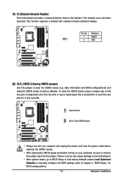
... chassis intrusion detection design. Definition 1 Signal 1 2 GND 20) CLR_CMOS (Clearing CMOS Jumper) Use this jumper to touch the two pins for BIOS configurations). - 37 - Hardware Installation Pin No. To clear the CMOS values, place a jumper cap on your computer and unplug the power cord ...jumper. Open: Normal Short: Clear CMOS Values • Always turn off your computer, be sure to factory defaults. date information and BIOS configurations) and reset the CMOS values to remove the jumper cap from the power outlet before clearing the CMOS values. • After...
... chassis intrusion detection design. Definition 1 Signal 1 2 GND 20) CLR_CMOS (Clearing CMOS Jumper) Use this jumper to touch the two pins for BIOS configurations). - 37 - Hardware Installation Pin No. To clear the CMOS values, place a jumper cap on your computer and unplug the power cord ...jumper. Open: Normal Short: Clear CMOS Values • Always turn off your computer, be sure to factory defaults. date information and BIOS configurations) and reset the CMOS values to remove the jumper cap from the power outlet before clearing the CMOS values. • After...

Manual
Page 38
... negative side (-) of the battery (the positive side should face up). • Used batteries must be lost. GA-EX58-UD4P Motherboard - 38 - 21) BAT (BATTERY) The battery provides power to keep the values (such as BIOS configurations, date, and time information) in the CMOS when the computer is replaced with an incorrect model. •...
... negative side (-) of the battery (the positive side should face up). • Used batteries must be lost. GA-EX58-UD4P Motherboard - 38 - 21) BAT (BATTERY) The battery provides power to keep the values (such as BIOS configurations, date, and time information) in the CMOS when the computer is replaced with an incorrect model. •...

Manual
Page 41
... the current version of BIOS from the Internet and updates the BIOS. BIOS Setup To access the BIOS Setup program, press the key during system startup, saving system parameters and loading operating system, etc. To upgrade the BIOS, use either the GIGABYTE Q-Flash or @BIOS utility. • Q-Flash... allows the user to boot. If this chapter or introductions of the BIOS Setup program. Its major functions include conducting the Power-On Self-...
... the current version of BIOS from the Internet and updates the BIOS. BIOS Setup To access the BIOS Setup program, press the key during system startup, saving system parameters and loading operating system, etc. To upgrade the BIOS, use either the GIGABYTE Q-Flash or @BIOS utility. • Q-Flash... allows the user to boot. If this chapter or introductions of the BIOS Setup program. Its major functions include conducting the Power-On Self-...
Manual
Page 42
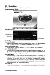
...order will directly boot from the device configured in Boot Menu. A. To exit Boot Menu, press . The LOGO Screen (Default) B. Function Keys : BIOS Setup : XpressRecovery2 : Boot Menu : Qflash 11/17/2008-X58-ICH10-7A89QG08C-00 Function Keys Function Keys: : POST SCREEN Press the key to access ...system will still be used for one time only. GA-EX58-UD4P Motherboard - 42 - 2-1 Startup Screen The following screens may appear when the computer boots. You can be based on page 58. : BIOS SETUP\Q-FLASH Press the key to enter BIOS Setup or to access the Q-Flash utility in Boot...
...order will directly boot from the device configured in Boot Menu. A. To exit Boot Menu, press . The LOGO Screen (Default) B. Function Keys : BIOS Setup : XpressRecovery2 : Boot Menu : Qflash 11/17/2008-X58-ICH10-7A89QG08C-00 Function Keys Function Keys: : POST SCREEN Press the key to access ...system will still be used for one time only. GA-EX58-UD4P Motherboard - 42 - 2-1 Startup Screen The following screens may appear when the computer boots. You can be based on page 58. : BIOS SETUP\Q-FLASH Press the key to enter BIOS Setup or to access the Q-Flash utility in Boot...

Manual
Page 43
...Saving Security Chip Configuration ESC: Quit F8: Q-Flash Select Item F10: Save & Exit Setup F11: Save CMOS to BIOS F12: Load CMOS from BIOS Main Menu Help The onscreen description of a highlighted setup option is not stable as shown below) appears on the bottom line ...current submenus Access the Q-Flash utility Display system information Save all the changes and exit the BIOS Setup program Save CMOS to BIOS Load CMOS from BIOS Change CPU's Clock & Voltage BIOS Setup Program Function Keys Move the selection bar to select an item Execute command or enter...
...Saving Security Chip Configuration ESC: Quit F8: Q-Flash Select Item F10: Save & Exit Setup F11: Save CMOS to BIOS F12: Load CMOS from BIOS Main Menu Help The onscreen description of a highlighted setup option is not stable as shown below) appears on the bottom line ...current submenus Access the Q-Flash utility Display system information Save all the changes and exit the BIOS Setup program Save CMOS to BIOS Load CMOS from BIOS Change CPU's Clock & Voltage BIOS Setup Program Function Keys Move the selection bar to select an item Execute command or enter...


