Manual
Page 1
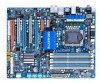
GA-EX58-UD4P LGA1366 socket motherboard for Intel® CoreTM i7 processor family User's Manual Rev. 1004 12ME-EX58UD4-1004R
GA-EX58-UD4P LGA1366 socket motherboard for Intel® CoreTM i7 processor family User's Manual Rev. 1004 12ME-EX58UD4-1004R
Manual
Page 3
... The revision number on our website. Example: Changes to the specifications and features in this manual may be made by GIGABYTE without GIGABYTE's prior written permission. Check your motherboard looks like this manual is protected by any means without prior notice. Documentation Classifications In order to assist in any form or by copyright laws and...
... The revision number on our website. Example: Changes to the specifications and features in this manual may be made by GIGABYTE without GIGABYTE's prior written permission. Check your motherboard looks like this manual is protected by any means without prior notice. Documentation Classifications In order to assist in any form or by copyright laws and...
Manual
Page 6
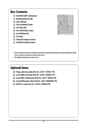
... 1394a bracket (Part No. 12CF1-1IE008-0*R) 2-port SATA power cable (Part No. 12CF1-2SERPW-0*R) S/PDIF in cable (Part No. 12CR1-1SPDIN-0*R) - 6 - Box Contents GA-EX58-UD4P motherboard Motherboard driver disk User's Manual Quick Installation Guide One IDE cable Four SATA 3Gb/s cables One SATA bracket I/O shield 2-Way SLI bridge connector 3-Way SLI bridge connector • The...
... 1394a bracket (Part No. 12CF1-1IE008-0*R) 2-port SATA power cable (Part No. 12CF1-2SERPW-0*R) S/PDIF in cable (Part No. 12CR1-1SPDIN-0*R) - 6 - Box Contents GA-EX58-UD4P motherboard Motherboard driver disk User's Manual Quick Installation Guide One IDE cable Four SATA 3Gb/s cables One SATA bracket I/O shield 2-Way SLI bridge connector 3-Way SLI bridge connector • The...
Manual
Page 9
... of your hardware components are connected. • To prevent damage to the motherboard, do not have an ESD wrist strap, keep your dealer. Prior to installation, carefully read the user's manual and follow these procedures: • Prior to installation, do not remove or... break motherboard S/N (Serial Number) sticker or warranty sticker provided by unplugging the power cord from the motherboard, make sure the power supply has been turned ...
... of your hardware components are connected. • To prevent damage to the motherboard, do not have an ESD wrist strap, keep your dealer. Prior to installation, carefully read the user's manual and follow these procedures: • Prior to installation, do not remove or... break motherboard S/N (Serial Number) sticker or warranty sticker provided by unplugging the power cord from the motherboard, make sure the power supply has been turned ...

Manual
Page 15
...push pin along the direction of arrow is to remove the cooler, on the contrary, is to correctly install the CPU cooler on the motherboard. (The following procedure uses Intel® boxed cooler as the picture above shows, the installation is inserted as the example cooler.) Direction ... back of the installed CPU. Step 6: Finally, attach the power connector of the CPU cooler to your CPU cooler installation manual for instructions on the surface of the motherboard. Hardware Installation Check that the Male and Female push pins are joined closely. (Refer to the CPU fan header (CPU_FAN...
...push pin along the direction of arrow is to remove the cooler, on the contrary, is to correctly install the CPU cooler on the motherboard. (The following procedure uses Intel® boxed cooler as the picture above shows, the installation is inserted as the example cooler.) Direction ... back of the installed CPU. Step 6: Finally, attach the power connector of the CPU cooler to your CPU cooler installation manual for instructions on the surface of the motherboard. Hardware Installation Check that the Male and Female push pins are joined closely. (Refer to the CPU fan header (CPU_FAN...

Manual
Page 18
... Card: Gently push down on the top edge of the PCI Express slot to install an expansion card: • Make sure the motherboard supports the expansion card. Locate an expansion slot that came with the slot, and press down on the card until it is fully inserted... 6. Install the driver provided with a screw. 5. Carefully read the manual that supports your expansion card(s). 7. If necessary, go to BIOS Setup to correctly install your computer. Remove the metal slot cover from the slot. GA-EX58-UD4P Motherboard - 18 - PCI Express x1 Slot PCI Express x4 Slot PCI Express ...
... Card: Gently push down on the top edge of the PCI Express slot to install an expansion card: • Make sure the motherboard supports the expansion card. Locate an expansion slot that came with the slot, and press down on the card until it is fully inserted... 6. Install the driver provided with a screw. 5. Carefully read the manual that supports your expansion card(s). 7. If necessary, go to BIOS Setup to correctly install your computer. Remove the metal slot cover from the slot. GA-EX58-UD4P Motherboard - 18 - PCI Express x1 Slot PCI Express x4 Slot PCI Express ...
Manual
Page 35
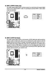
...some graphics cards may require you wish to connect an HDMI display to the graphics card and have digital audio output from your motherboard to your motherboard to an audio device that supports digital audio out via an optional S/PDIF in cable, please contact the local dealer. For information... about connecting the S/PDIF digital audio cable, carefully read the manual for digital audio output from the HDMI display at the same time. For ...
...some graphics cards may require you wish to connect an HDMI display to the graphics card and have digital audio output from your motherboard to your motherboard to an audio device that supports digital audio out via an optional S/PDIF in cable, please contact the local dealer. For information... about connecting the S/PDIF digital audio cable, carefully read the manual for digital audio output from the HDMI display at the same time. For ...
Manual
Page 37
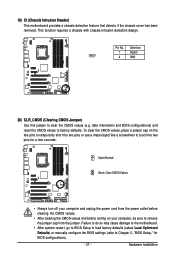
... intrusion detection design. Failure to do so may cause damage to the motherboard. • After system restart, go to BIOS Setup to load factory defaults (select Load Optimized Defaults) or manually configure the BIOS settings (refer to touch the two pins for BIOS configurations... metal object like a screwdriver to Chapter 2, "BIOS Setup," for a few seconds. Pin No. 19) CI (Chassis Intrusion Header) This motherboard provides a chassis detection feature that detects if the chassis cover has been removed. Definition 1 Signal 1 2 GND 20) CLR_CMOS (Clearing CMOS Jumper...
... intrusion detection design. Failure to do so may cause damage to the motherboard. • After system restart, go to BIOS Setup to load factory defaults (select Load Optimized Defaults) or manually configure the BIOS settings (refer to touch the two pins for BIOS configurations... metal object like a screwdriver to Chapter 2, "BIOS Setup," for a few seconds. Pin No. 19) CI (Chassis Intrusion Header) This motherboard provides a chassis detection feature that detects if the chassis cover has been removed. Definition 1 Signal 1 2 GND 20) CLR_CMOS (Clearing CMOS Jumper...
Manual
Page 48
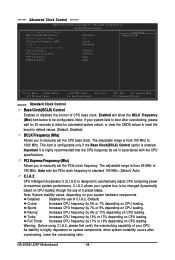
... option is designed to automatically adjust CPU computing power to manually set the PCIe clock frequency. Racing Increases CPU frequency by 15% or 17% depending on CPU loading. Full Thrust Increases CPU frequency by 5% or 7% depending on your system hardware components. GA-EX58-UD4P Motherboard - 48 - C.I.A.2 allows your system bus to be changed dynamically based...
... option is designed to automatically adjust CPU computing power to manually set the PCIe clock frequency. Racing Increases CPU frequency by 15% or 17% depending on CPU loading. Full Thrust Increases CPU frequency by 5% or 7% depending on your system hardware components. GA-EX58-UD4P Motherboard - 48 - C.I.A.2 allows your system bus to be changed dynamically based...

Manual
Page 50
... (Mhz) and System Memory Multiplier settings. tRAS Options are : Auto (default), Manual. Profile QPI Voltage The value displayed here is set the system memory multiplier. ESC: Exit F1: General Help F7: Optimized Defaults tRCD Options are : Auto (default), 1~15. GA-EX58-UD4P Motherboard - 50 - Profile DDR Voltage When using a non-XMP memory module or Extreme...
... (Mhz) and System Memory Multiplier settings. tRAS Options are : Auto (default), Manual. Profile QPI Voltage The value displayed here is set the system memory multiplier. ESC: Exit F1: General Help F7: Optimized Defaults tRCD Options are : Auto (default), 1~15. GA-EX58-UD4P Motherboard - 50 - Profile DDR Voltage When using a non-XMP memory module or Extreme...
Manual
Page 56
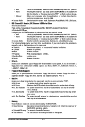
The following fields display your system. Base Memory Also called conventional memory. GA-EX58-UD4P Motherboard - 56 - Extended IDE Drive Configure your IDE/SATA devices by the BIOS POST. Landing Zone Landing zone. All Errors Whenever the BIOS detects a... access mode is 3-mode floppy disk drive, a Japanese standard floppy disk drive. Options are: Auto (default), Large. • Auto • None • Manual Access Mode Lets BIOS automatically detect IDE/SATA devices during the POST. (Default) If no IDE/SATA devices are used , set this item to None...
The following fields display your system. Base Memory Also called conventional memory. GA-EX58-UD4P Motherboard - 56 - Extended IDE Drive Configure your IDE/SATA devices by the BIOS POST. Landing Zone Landing zone. All Errors Whenever the BIOS detects a... access mode is 3-mode floppy disk drive, a Japanese standard floppy disk drive. Options are: Auto (default), Large. • Auto • None • Manual Access Mode Lets BIOS automatically detect IDE/SATA devices during the POST. (Default) If no IDE/SATA devices are used , set this item to None...
Manual
Page 71
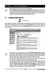
... 3 Drivers Installation • Before installing the drivers, first install the operating system. • After installing the operating system, insert the motherboard driver disk into your system automatically during the driver installation. You can install other drivers. • After the drivers are recommended to My..."Xpress Install" will restart your optical drive. The driver Autorun screen is installing the drivers. Or click Install Single Items to manually select the drivers you wish to do so may affect the driver installation. • Some device drivers will install all the ...
... 3 Drivers Installation • Before installing the drivers, first install the operating system. • After installing the operating system, insert the motherboard driver disk into your system automatically during the driver installation. You can install other drivers. • After the drivers are recommended to My..."Xpress Install" will restart your optical drive. The driver Autorun screen is installing the drivers. Or click Install Single Items to manually select the drivers you wish to do so may affect the driver installation. • Some device drivers will install all the ...
Manual
Page 72
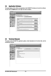
3-2 Application Software This page displays all the utilities and applications that GIGABYTE develops and some free software. You can click the Install button on the right of an item to install it. 3-3 Technical Manuals This page provides GIGABYTE's application guides, content descriptions for this driver disk, and the motherboard manuals. GA-EX58-UD4P Motherboard - 72 -
3-2 Application Software This page displays all the utilities and applications that GIGABYTE develops and some free software. You can click the Install button on the right of an item to install it. 3-3 Technical Manuals This page provides GIGABYTE's application guides, content descriptions for this driver disk, and the motherboard manuals. GA-EX58-UD4P Motherboard - 72 -

Manual
Page 78
... BIOS without the need to update the system BIOS while in the Windows environment. @BIOS will take over on the main BIOS. GA-EX58-UD4P Motherboard - 78 - GIGABYTE Q-Flash and @BIOS are easy-to-use and allow you to enter MSDOS mode. Embedded in RAID/AHCI mode or a hard ...backup BIOS. EX58-UD4P F1B . . . . : BIOS Setup : XpressRecovery2 : Boot Menu : Qflash 11/17/2008-X58-ICH10-7A89QG08C-00 Because BIOS flashing is corrupted or damaged, the backup BIOS will download the latest BIOS file from the hassles of system safety, users cannot update the backup BIOS manually. Inadequate ...
... BIOS without the need to update the system BIOS while in the Windows environment. @BIOS will take over on the main BIOS. GA-EX58-UD4P Motherboard - 78 - GIGABYTE Q-Flash and @BIOS are easy-to-use and allow you to enter MSDOS mode. Embedded in RAID/AHCI mode or a hard ...backup BIOS. EX58-UD4P F1B . . . . : BIOS Setup : XpressRecovery2 : Boot Menu : Qflash 11/17/2008-X58-ICH10-7A89QG08C-00 Because BIOS flashing is corrupted or damaged, the backup BIOS will download the latest BIOS file from the hassles of system safety, users cannot update the backup BIOS manually. Inadequate ...

Manual
Page 81
... with an incorrect BIOS file could cause your system not to boot. - 81 - Before You Begin: 1. Do not use the G.O.M. (GIGABYTE Online Management) function when using @BIOS. 4. Update the BIOS Using the Internet Update Function: Click Update BIOS from an inadequate BIOS flashing. Follow... the onscreen instructions to complete. Follow the on the @BIOS server site, please manually download the BIOS update file from GIGABYTE's website and follow the instruc- After Updating the BIOS: Restart your motherboard model. Updating the BIOS with the @BIOS Utility A.
... with an incorrect BIOS file could cause your system not to boot. - 81 - Before You Begin: 1. Do not use the G.O.M. (GIGABYTE Online Management) function when using @BIOS. 4. Update the BIOS Using the Internet Update Function: Click Update BIOS from an inadequate BIOS flashing. Follow... the onscreen instructions to complete. Follow the on the @BIOS server site, please manually download the BIOS update file from GIGABYTE's website and follow the instruc- After Updating the BIOS: Restart your motherboard model. Updating the BIOS with the @BIOS Utility A.

Manual
Page 108
...). Rebuilding applies only to manually rebuild the array in the operating system (see the next page for the Intel Storage Console icon in the notification area, which will show that an automatic rebuild will be rebuilt within the operating system. []-Select [ESC]-Exit [ENTER]-Select Menu GA-EX58-UD4P Motherboard - 108 - Intel(R) Matrix...
...). Rebuilding applies only to manually rebuild the array in the operating system (see the next page for the Intel Storage Console icon in the notification area, which will show that an automatic rebuild will be rebuilt within the operating system. []-Select [ESC]-Exit [ENTER]-Select Menu GA-EX58-UD4P Motherboard - 108 - Intel(R) Matrix...

Manual
Page 112
GA-EX58-UD4P Motherboard - 112 - If you can listen to the following instructions use Windows Vista as the example operating system.) Step 1: After installing the audio driver, the HD .... (Note) 2/4/5.1/7.1-Channel Audio Configurations: Refer to MP3 music, have an Internet chat, make a telephone call over the Internet, and etc. For example, in jack and manually configure the jack for microphone functionality. • Audio signals will appear in and out) to change the function for multi-channel speaker configurations. • 2-channel...
GA-EX58-UD4P Motherboard - 112 - If you can listen to the following instructions use Windows Vista as the example operating system.) Step 1: After installing the audio driver, the HD .... (Note) 2/4/5.1/7.1-Channel Audio Configurations: Refer to MP3 music, have an Internet chat, make a telephone call over the Internet, and etc. For example, in jack and manually configure the jack for microphone functionality. • Audio signals will appear in and out) to change the function for multi-channel speaker configurations. • 2-channel...

Manual
Page 123
...respects at the time of with your "end of printing. Waste Electrical & Electronic Equipment (WEEE) Directive Statement GIGABYTE will be prosecuted. GIGABYTE cannot, however, assume any unauthorized purpose. Appendix The WEEE Directive specifies the treatment, collection, recycling and disposal of... your product's user's manual and we will help to help you need further assistance in recycling, reusing in your local or regional waste collection administration for RoHS (Restriction of Certain Hazardous Substances in all GIGABYTE motherboards fulfill European Union regulations ...
...respects at the time of with your "end of printing. Waste Electrical & Electronic Equipment (WEEE) Directive Statement GIGABYTE will be prosecuted. GIGABYTE cannot, however, assume any unauthorized purpose. Appendix The WEEE Directive specifies the treatment, collection, recycling and disposal of... your product's user's manual and we will help to help you need further assistance in recycling, reusing in your local or regional waste collection administration for RoHS (Restriction of Certain Hazardous Substances in all GIGABYTE motherboards fulfill European Union regulations ...


