Manual
Page 1
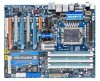
GA-EX58-EXTREME LGA1366 socket motherboard for Intel® CoreTM i7 processor family User's Manual Rev. 1004 12ME-EX58EX-1004R
GA-EX58-EXTREME LGA1366 socket motherboard for Intel® CoreTM i7 processor family User's Manual Rev. 1004 12ME-EX58EX-1004R
Manual
Page 3
..., drivers, or when looking for technical information. No part of this manual are legally registered to use of this product, GIGABYTE provides the following types of documentations: For quick set-up of GIGABYTE. For example, "REV: 1.0" means the revision of the motherboard is... to the specifications and features in this manual may be made by GIGABYTE without GIGABYTE's prior written permission. Copyright © 2009 GIGA-BYTE TECHNOLOGY CO., LTD. For product-related information, check on our website at: http://www.gigabyte.com.tw Identifying Your Motherboard Revision The ...
..., drivers, or when looking for technical information. No part of this manual are legally registered to use of this product, GIGABYTE provides the following types of documentations: For quick set-up of GIGABYTE. For example, "REV: 1.0" means the revision of the motherboard is... to the specifications and features in this manual may be made by GIGABYTE without GIGABYTE's prior written permission. Copyright © 2009 GIGA-BYTE TECHNOLOGY CO., LTD. For product-related information, check on our website at: http://www.gigabyte.com.tw Identifying Your Motherboard Revision The ...
Manual
Page 5
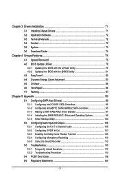
Chapter 3 Drivers Installation 71 3-1 Installing Chipset Drivers 71 3-2 Application Software 72 3-3 Technical Manuals 72 3-4 Contact ...73 3-5 System ...73 3-6 Download Center 74 Chapter 4 Unique Features 75 4-1 Xpress Recovery2 75 4-2 BIOS Update ... Time Repair ...86 4-7 Teaming ...87 Chapter 5 Appendix ...89 5-1 Configuring SATA Hard Drive(s 89 5-1-1 Configuring Intel ICH10R SATA Controllers 89 5-1-2 Configuring GIGABYTE SATA2/JMB322 SATA Controller 95 5-1-3 Making a SATA RAID/AHCI Driver Diskette 97 5-1-4 Installing the SATA RAID/AHCI Driver and Operating System 99 5-1-5 Smart ...
Chapter 3 Drivers Installation 71 3-1 Installing Chipset Drivers 71 3-2 Application Software 72 3-3 Technical Manuals 72 3-4 Contact ...73 3-5 System ...73 3-6 Download Center 74 Chapter 4 Unique Features 75 4-1 Xpress Recovery2 75 4-2 BIOS Update ... Time Repair ...86 4-7 Teaming ...87 Chapter 5 Appendix ...89 5-1 Configuring SATA Hard Drive(s 89 5-1-1 Configuring Intel ICH10R SATA Controllers 89 5-1-2 Configuring GIGABYTE SATA2/JMB322 SATA Controller 95 5-1-3 Making a SATA RAID/AHCI Driver Diskette 97 5-1-4 Installing the SATA RAID/AHCI Driver and Operating System 99 5-1-5 Smart ...
Manual
Page 6
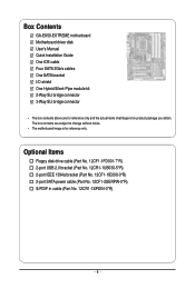
... power cable (Part No. 12CF1-2SERPW-0*R) S/PDIF in cable (Part No. 12CR1-1SPDIN-0*R) - 6 - The box contents are for reference only. Box Contents GA-EX58-EXTREME motherboard Motherboard driver disk User's Manual Quick Installation Guide One IDE cable Four SATA 3Gb/s cables One SATA bracket I/O shield One Hybrid Silent-Pipe module kit 2-Way SLI bridge...
... power cable (Part No. 12CF1-2SERPW-0*R) S/PDIF in cable (Part No. 12CR1-1SPDIN-0*R) - 6 - The box contents are for reference only. Box Contents GA-EX58-EXTREME motherboard Motherboard driver disk User's Manual Quick Installation Guide One IDE cable Four SATA 3Gb/s cables One SATA bracket I/O shield One Hybrid Silent-Pipe module kit 2-Way SLI bridge...
Manual
Page 9
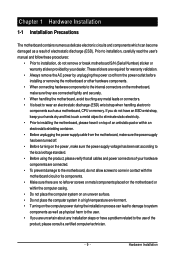
Prior to installation, carefully read the user's manual and follow these procedures: • Prior to installation, do not remove or break motherboard S/N (Serial Number) sticker or warranty sticker provided by unplugging the power ...
Prior to installation, carefully read the user's manual and follow these procedures: • Prior to installation, do not remove or break motherboard S/N (Serial Number) sticker or warranty sticker provided by unplugging the power ...
Manual
Page 15
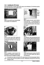
Check that the Male and Female push pins are joined closely. (Refer to your CPU cooler installation manual for instructions on installing the cooler.) Step 5: After the installation, check the back of arrow is to remove the cooler, on the contrary, is to ... an even and thin layer of thermal grease on the surface of the CPU cooler to the CPU fan header (CPU_FAN) on the motherboard. Use extreme care when removing the CPU cooler because the thermal grease/tape between the CPU cooler and CPU may damage the CPU. - 15 - Step 2: Before installing...
Check that the Male and Female push pins are joined closely. (Refer to your CPU cooler installation manual for instructions on installing the cooler.) Step 5: After the installation, check the back of arrow is to remove the cooler, on the contrary, is to ... an even and thin layer of thermal grease on the surface of the CPU cooler to the CPU fan header (CPU_FAN) on the motherboard. Use extreme care when removing the CPU cooler because the thermal grease/tape between the CPU cooler and CPU may damage the CPU. - 15 - Step 2: Before installing...
Manual
Page 19
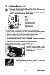
... in the slot. 3. Hardware Installation 1-6 Installing an Expansion Card Read the following guidelines before installing an expansion card to prevent hardware damage. Carefully read the manual that supports your expansion card. • Always turn off the computer and unplug the power cord from the power outlet before you begin to make...
... in the slot. 3. Hardware Installation 1-6 Installing an Expansion Card Read the following guidelines before installing an expansion card to prevent hardware damage. Carefully read the manual that supports your expansion card. • Always turn off the computer and unplug the power cord from the power outlet before you begin to make...
Manual
Page 22
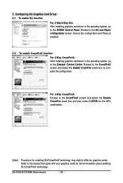
...installing graphics card driver in the operating system, go to the NVIDIA Control Panel. For 3-Way CrossFireX: Browse to the manual that came with your graphics cards for enabling SLI/CrossFireX technology may slightly differ by graphics cards. Refer to the CrossFireX ... the GPU combination. (Note) Procedure for more information about enabling SLI/CrossFireX technology. Ensure SLI configuration and Physx is enabled. C. GA-EX58-EXTREME Motherboard - 22 - Browse to complete the configuration. Browse to the CrossFireX screen and select the Enable CrossFire check box to the ...
...installing graphics card driver in the operating system, go to the NVIDIA Control Panel. For 3-Way CrossFireX: Browse to the manual that came with your graphics cards for enabling SLI/CrossFireX technology may slightly differ by graphics cards. Refer to the CrossFireX ... the GPU combination. (Note) Procedure for more information about enabling SLI/CrossFireX technology. Ensure SLI configuration and Physx is enabled. C. GA-EX58-EXTREME Motherboard - 22 - Browse to complete the configuration. Browse to the CrossFireX screen and select the Enable CrossFire check box to the ...
Manual
Page 36
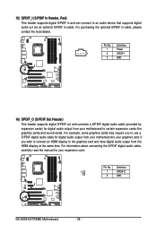
... to an audio device that supports digital audio out via an optional S/PDIF in cable. Definition 1 1 SPDIFO 2 GND GA-EX58-EXTREME Motherboard - 36 - For information about connecting the S/PDIF digital audio cable, carefully read the manual for digital audio output from your motherboard to your graphics card if you wish to connect an HDMI...
... to an audio device that supports digital audio out via an optional S/PDIF in cable. Definition 1 1 SPDIFO 2 GND GA-EX58-EXTREME Motherboard - 36 - For information about connecting the S/PDIF digital audio cable, carefully read the manual for digital audio output from your motherboard to your graphics card if you wish to connect an HDMI...
Manual
Page 38
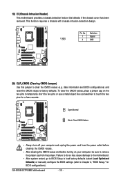
... the motherboard. • After system restart, go to BIOS Setup to load factory defaults (select Load Optimized Defaults) or manually configure the BIOS settings (refer to touch the two pins for BIOS configurations). GA-EX58-EXTREME Motherboard - 38 - To clear the CMOS values, place a jumper cap on your computer, be sure to remove the...
... the motherboard. • After system restart, go to BIOS Setup to load factory defaults (select Load Optimized Defaults) or manually configure the BIOS settings (refer to touch the two pins for BIOS configurations). GA-EX58-EXTREME Motherboard - 38 - To clear the CMOS values, place a jumper cap on your computer, be sure to remove the...
Manual
Page 48
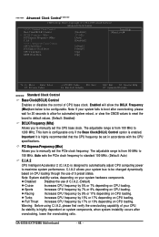
..., when system instability occurs after overclocking, please wait for 20 seconds to allow the BCLK Frequency (Mhz)item below to 150 MHz. GA-EX58-EXTREME Motherboard - 48 - C.I.A.2 allows your CPU. Enabled will allow for automated system reboot, or clear the CMOS values to reset the... Frequency (Mhz) Allows you to be set in accordance with the CPU specifications. Disabled Disables the use of your system bus to manually set the CPU base clock. Auto sets the PCIe clock frequency to maximize system performance. Note: If your system hardware components. Warning...
..., when system instability occurs after overclocking, please wait for 20 seconds to allow the BCLK Frequency (Mhz)item below to 150 MHz. GA-EX58-EXTREME Motherboard - 48 - C.I.A.2 allows your CPU. Enabled will allow for automated system reboot, or clear the CMOS values to reset the... Frequency (Mhz) Allows you to be set in accordance with the CPU specifications. Disabled Disables the use of your system bus to manually set the CPU base clock. Auto sets the PCIe clock frequency to maximize system performance. Note: If your system hardware components. Warning...
Manual
Page 50
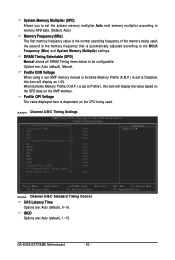
...will display as 1.5V. Options are : Auto (default), 1~15. ESC: Exit F1: General Help F7: Optimized Defaults GA-EX58-EXTREME Motherboard - 50 - Profile DDR Voltage When using a non-XMP memory module or Extreme Memory Profile (X.M.P.) is dependent on the XMP memory. the second is the memory frequency that is set to Profile1...) Memory Frequency (Mhz) The first memory frequency value is the normal operating frequency of the memory being used ; tRCD Options are : Auto (default), Manual. DRAM Timing Selectable (SPD) Manual allows all DRAM Timing items below to be configurable.
...will display as 1.5V. Options are : Auto (default), 1~15. ESC: Exit F1: General Help F7: Optimized Defaults GA-EX58-EXTREME Motherboard - 50 - Profile DDR Voltage When using a non-XMP memory module or Extreme Memory Profile (X.M.P.) is dependent on the XMP memory. the second is the memory frequency that is set to Profile1...) Memory Frequency (Mhz) The first memory frequency value is the normal operating frequency of the memory being used ; tRCD Options are : Auto (default), Manual. DRAM Timing Selectable (SPD) Manual allows all DRAM Timing items below to be configurable.
Manual
Page 56
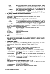
...(Default) All, But Diskette The system boot will not stop for a floppy disk drive error but it will stop for faster system startup. GA-EX58-EXTREME Motherboard - 56 - The following fields display your IDE/SATA devices by the BIOS POST. Cylinder Number of sectors. Landing Zone Landing zone....your hard drive specifications. Floppy 3 Mode Support Allows you to determine whether the system will stop . • Auto • None • Manual Access Mode Lets BIOS automatically detect IDE/SATA devices during the POST. (Default) If no IDE/SATA devices are used , set this item to...
...(Default) All, But Diskette The system boot will not stop for a floppy disk drive error but it will stop for faster system startup. GA-EX58-EXTREME Motherboard - 56 - The following fields display your IDE/SATA devices by the BIOS POST. Cylinder Number of sectors. Landing Zone Landing zone....your hard drive specifications. Floppy 3 Mode Support Allows you to determine whether the system will stop . • Auto • None • Manual Access Mode Lets BIOS automatically detect IDE/SATA devices during the POST. (Default) If no IDE/SATA devices are used , set this item to...
Manual
Page 71
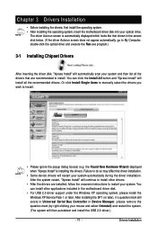
... driver disk, "Xpress Install" will continue to install. Failure to install. • Please ignore the popup dialog box(es) (e.g. Or click Install Single Items to manually select the drivers you wish to do so may affect the driver installation. • Some device drivers will then autodetect and install the USB 2.0 driver...
... driver disk, "Xpress Install" will continue to install. Failure to install. • Please ignore the popup dialog box(es) (e.g. Or click Install Single Items to manually select the drivers you wish to do so may affect the driver installation. • Some device drivers will then autodetect and install the USB 2.0 driver...
Manual
Page 72
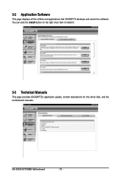
3-2 Application Software This page displays all the utilities and applications that GIGABYTE develops and some free software. You can click the Install button on the right of an item to install it. 3-3 Technical Manuals This page provides GIGABYTE's application guides, content descriptions for this driver disk, and the motherboard manuals. GA-EX58-EXTREME Motherboard - 72 -
3-2 Application Software This page displays all the utilities and applications that GIGABYTE develops and some free software. You can click the Install button on the right of an item to install it. 3-3 Technical Manuals This page provides GIGABYTE's application guides, content descriptions for this driver disk, and the motherboard manuals. GA-EX58-EXTREME Motherboard - 72 -
Manual
Page 73
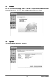
3-4 Contact Click the URL on this manual to the GIGABYTE Web site. Drivers Installation Or read the last page of this page to link to check the contact information for GIGABYTE Taiwan headquarter or worldwide branch offices. 3-5 System This page provides the basic system information. - 73 -
3-4 Contact Click the URL on this manual to the GIGABYTE Web site. Drivers Installation Or read the last page of this page to link to check the contact information for GIGABYTE Taiwan headquarter or worldwide branch offices. 3-5 System This page provides the basic system information. - 73 -
Manual
Page 78
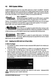
...GIGABYTE's website, download the latest compressed BIOS update file that support DualBIOS have two BIOS onboard, a main BIOS and a backup BIOS. During the POST, press the key to access Q-Flash. EX58-EXTREME D22 . . . . : BIOS Setup : XpressRecovery2 : Boot Menu : Qflash 10/15/2008-X58-ICH10-7A89QG02C-00 Because BIOS flashing is DualBIOS ? GA-EX58-EXTREME... Copyright (C) 1984-2008, Award Software, Inc. For the sake of system safety, users cannot update the backup BIOS manually. TM Motherboards that matches your motherboard model. 2. What is @BIOS ? Note: The USB flash drive or hard ...
...GIGABYTE's website, download the latest compressed BIOS update file that support DualBIOS have two BIOS onboard, a main BIOS and a backup BIOS. During the POST, press the key to access Q-Flash. EX58-EXTREME D22 . . . . : BIOS Setup : XpressRecovery2 : Boot Menu : Qflash 10/15/2008-X58-ICH10-7A89QG02C-00 Because BIOS flashing is DualBIOS ? GA-EX58-EXTREME... Copyright (C) 1984-2008, Award Software, Inc. For the sake of system safety, users cannot update the backup BIOS manually. TM Motherboards that matches your motherboard model. 2. What is @BIOS ? Note: The USB flash drive or hard ...
Manual
Page 81
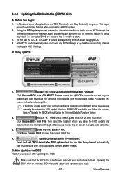
... you save the current BIOS file. 4. Follow the on the @BIOS server site, please manually download the BIOS update file from an inadequate BIOS flashing. Unique Features Do not use the G.O.M. (GIGABYTE Online Management) function when using @BIOS. 4. Using @BIOS: 1. Load BIOS defaults after BIOS... Utility A. Failure to be flashed matches your motherboard model. Follow the onscreen instructions to save the BIOS update file obtained from GIGABYTE Server, select the @BIOS server site closest to your location and then download the BIOS file that the BIOS file to do...
... you save the current BIOS file. 4. Follow the on the @BIOS server site, please manually download the BIOS update file from an inadequate BIOS flashing. Unique Features Do not use the G.O.M. (GIGABYTE Online Management) function when using @BIOS. 4. Using @BIOS: 1. Load BIOS defaults after BIOS... Utility A. Failure to be flashed matches your motherboard model. Follow the onscreen instructions to save the BIOS update file obtained from GIGABYTE Server, select the @BIOS server site closest to your location and then download the BIOS file that the BIOS file to do...
Manual
Page 87
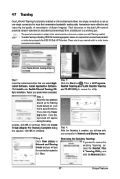
Fault tolerance on your hub's specifications. Restart your network switch or router device manual for further details. Step 2: Click the Start icon . Please refer to your system when completed. Then click the Teaming button. (Two dialog boxes will appear ...
Fault tolerance on your hub's specifications. Restart your network switch or router device manual for further details. Step 2: Click the Start icon . Please refer to your system when completed. Then click the Teaming button. (Two dialog boxes will appear ...
Manual
Page 102
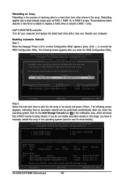
... Disk (0) Member Disk (0) Volumes with a new one. If you do not enable automatic rebuild on this stage, you have to manually rebuild the array in the op4.eraEtxinitg system. Rebuilding applies only to Non-RAID 4. The procedures below assume a new drive is being..."Press to enter Configuration Utility" appears, press + to be rebuilt within the operating system. []-Select [ESC]-Exit [ENTER]-Select Menu GA-EX58-EXTREME Motherboard - 102 - The following screen appears, indicating that a RAID volume is added to replace a failed drive to a hard drive from other...
... Disk (0) Member Disk (0) Volumes with a new one. If you do not enable automatic rebuild on this stage, you have to manually rebuild the array in the op4.eraEtxinitg system. Rebuilding applies only to Non-RAID 4. The procedures below assume a new drive is being..."Press to enter Configuration Utility" appears, press + to be rebuilt within the operating system. []-Select [ESC]-Exit [ENTER]-Select Menu GA-EX58-EXTREME Motherboard - 102 - The following screen appears, indicating that a RAID volume is added to replace a failed drive to a hard drive from other...


