
Manual
Page 2
Installing the Infineon TPM Driver and the Smart TPM Utility 4 2.1. Initializing the TPM chip 5 3.1. Advanced Mode...8 4. Creating a USB Key 18 4.2. Initializing the TPM Chip with the Smart TPM Utility 5 3.2. Table of Contents TPM Configuration Procedure 3 1. Installing the Smart TPM Utility 4 3. Configuring the Smart TPM Utility 18 4.1. Other Bluetooth Settings 21 4.4. Other Features...21 - 2 - Installing the Infineon TPM Driver 4 2.2. Configuring the System BIOS 3 2. Creating a Bluetooth Cell Phone Key 19 4.3.
Installing the Infineon TPM Driver and the Smart TPM Utility 4 2.1. Initializing the TPM chip 5 3.1. Advanced Mode...8 4. Creating a USB Key 18 4.2. Initializing the TPM Chip with the Smart TPM Utility 5 3.2. Table of Contents TPM Configuration Procedure 3 1. Installing the Smart TPM Utility 4 3. Configuring the Smart TPM Utility 18 4.1. Other Bluetooth Settings 21 4.4. Other Features...21 - 2 - Installing the Infineon TPM Driver 4 2.2. Configuring the System BIOS 3 2. Creating a Bluetooth Cell Phone Key 19 4.3.

Manual
Page 3
... to clear the TPM chip. TPM Configuration Procedure To enable the TPM, follow the steps below in the BIOS Setup program. - 3 - Configuring the Smart TPM utility 1. Previously encrypted files will appear. CMOS Setup Utility-Copyright (C) 1984-2009 Award Software Security Chip Configuration ... Chip Configuration menu and the following screen will become inaccessible after the TPM chip is cleared. Go to save changes and then exit the BIOS Setup program. To prevent the TPM settings being cleared by other users, we recommend that you set Security Chip to back up the encrypted...
... to clear the TPM chip. TPM Configuration Procedure To enable the TPM, follow the steps below in the BIOS Setup program. - 3 - Configuring the Smart TPM utility 1. Previously encrypted files will appear. CMOS Setup Utility-Copyright (C) 1984-2009 Award Software Security Chip Configuration ... Chip Configuration menu and the following screen will become inaccessible after the TPM chip is cleared. Go to save changes and then exit the BIOS Setup program. To prevent the TPM settings being cleared by other users, we recommend that you set Security Chip to back up the encrypted...

Manual
Page 5
... your Personal Secure Drive(PSD) Configure a Personal Secure Drive (PSD) here. Personal Secure Drive (PSD)" settings only. Initializing the TPM chip After configuring the system BIOS and installing the driver software, the Infineon Security Platform icon , which your PSD will be able to access/close your PSD data when connecting to...
... your Personal Secure Drive(PSD) Configure a Personal Secure Drive (PSD) here. Personal Secure Drive (PSD)" settings only. Initializing the TPM chip After configuring the system BIOS and installing the driver software, the Infineon Security Platform icon , which your PSD will be able to access/close your PSD data when connecting to...

Manual
Page 6
... allocates some space. Please note that the size you specify is 16 characters). Please also note that you cannot use the Security Platform in the BIOS Setup program. • This password incorporates the functionalities of the "Owner Password," "User Password," "Emergency Recovery Token Password," and "Password Reset Token Password" of the...
... allocates some space. Please note that the size you specify is 16 characters). Please also note that you cannot use the Security Platform in the BIOS Setup program. • This password incorporates the functionalities of the "Owner Password," "User Password," "Emergency Recovery Token Password," and "Password Reset Token Password" of the...

Manual
Page 7
... use as the portable Smart TPM user key and a screen similar to that you plug in the BIOS, the latter will be used for the Bluetooth enabled cell phone(s). Then enter the same passkey on ... than one USB flash drive at the same time. Enter a passkey (8~16 digits recommended) in the system BIOS. Create a USB key: Select the Use USB storage check box and click Refresh to use as the portable... Smart TPM user key. Upon completing the steps above, click OK to BIOS check box will appear. Then select the USB flash drive that on the left will store the...
... use as the portable Smart TPM user key and a screen similar to that you plug in the BIOS, the latter will be used for the Bluetooth enabled cell phone(s). Then enter the same passkey on ... than one USB flash drive at the same time. Enter a passkey (8~16 digits recommended) in the system BIOS. Create a USB key: Select the Use USB storage check box and click Refresh to use as the portable... Smart TPM user key. Upon completing the steps above, click OK to BIOS check box will appear. Then select the USB flash drive that on the left will store the...

Manual
Page 18
...be cracked or read. • Though the TPM delivers the latest data security technology, it does not guarantee data integrity or provide hardware protection. GIGABYTE is not liable for loss of encrypted data as shown below. Users can access data. • After creating the password(s) and key(s) associated with... the USB flash drive inserted, click Refresh to let Smart TPM re-detect the device.) If more than one user uses the "Enable Bacup to BIOS" function to store their PSD data by simply connecting to create a portable user key using a Bluetooth cell phone or USB flash drive. 4. Step...
...be cracked or read. • Though the TPM delivers the latest data security technology, it does not guarantee data integrity or provide hardware protection. GIGABYTE is not liable for loss of encrypted data as shown below. Users can access data. • After creating the password(s) and key(s) associated with... the USB flash drive inserted, click Refresh to let Smart TPM re-detect the device.) If more than one user uses the "Enable Bacup to BIOS" function to store their PSD data by simply connecting to create a portable user key using a Bluetooth cell phone or USB flash drive. 4. Step...

Manual
Page 19
... the device.) Before creating a Bluetooth cell phone key, make sure your motherboard includes a Bluetooth receiver and turn off or reset your PSD by plugging in BIOS Setup and then set earlier and click OK to confirm, click Yes. Then the USB key is normal. You are able to access/close your...
... the device.) Before creating a Bluetooth cell phone key, make sure your motherboard includes a Bluetooth receiver and turn off or reset your PSD by plugging in BIOS Setup and then set earlier and click OK to confirm, click Yes. Then the USB key is normal. You are able to access/close your...

Manual
Page 3
... revision before updating motherboard BIOS, drivers, or when looking for technical information. Check your motherboard looks like this manual may be made by GIGABYTE without GIGABYTE's prior written permission. Changes to their respective owners. No part of GIGABYTE. Documentation Classifications In order... website. The trademarks mentioned in this manual may be reproduced, copied, translated, transmitted, or published in this product, GIGABYTE provides the following types of documentations: For quick set-up of the motherboard is the property of this manual...
... revision before updating motherboard BIOS, drivers, or when looking for technical information. Check your motherboard looks like this manual may be made by GIGABYTE without GIGABYTE's prior written permission. Changes to their respective owners. No part of GIGABYTE. Documentation Classifications In order... website. The trademarks mentioned in this manual may be reproduced, copied, translated, transmitted, or published in this product, GIGABYTE provides the following types of documentations: For quick set-up of the motherboard is the property of this manual...

Manual
Page 4
Table of Contents Box Contents ...6 OptionalItems ...6 GA-EP45T-UD3P Motherboard Layout 7 Block Diagram ...8 Chapter 1 Hardware Installation 9 1-1 Installation Precautions 9 1-2 Product Specifications 10 1-3 Installing the CPU and CPU Cooler 13...Installing the SATA Bracket 19 1-7 Back Panel Connectors 20 1-8 Internal Connectors 22 Chapter 2 BIOS Setup 35 2-1 Startup Screen 36 2-2 The Main Menu 37 2-3 MB Intelligent Tweaker(M.I.T 39 2-4 Standard CMOS Features 47 2-5 Advanced BIOS Features 49 2-6 IntegratedPeripherals 52 2-7 Power Management Setup 56 2-8 PnP/PCI Configurations 58 ...
Table of Contents Box Contents ...6 OptionalItems ...6 GA-EP45T-UD3P Motherboard Layout 7 Block Diagram ...8 Chapter 1 Hardware Installation 9 1-1 Installation Precautions 9 1-2 Product Specifications 10 1-3 Installing the CPU and CPU Cooler 13...Installing the SATA Bracket 19 1-7 Back Panel Connectors 20 1-8 Internal Connectors 22 Chapter 2 BIOS Setup 35 2-1 Startup Screen 36 2-2 The Main Menu 37 2-3 MB Intelligent Tweaker(M.I.T 39 2-4 Standard CMOS Features 47 2-5 Advanced BIOS Features 49 2-6 IntegratedPeripherals 52 2-7 Power Management Setup 56 2-8 PnP/PCI Configurations 58 ...

Manual
Page 5
...67 3-6 Download Center 68 Chapter 4 Unique Features 69 4-1 Xpress Recovery2 69 4-2 BIOS Update Utilities 74 4-2-1 Updating the BIOS with the Q-Flash Utility 74 4-2-2 Updating the BIOS with the @BIOS Utility 77 4-3 EasyTune 6 ...78 4-4 Dynamic Energy Saver Advanced 79 4-5 Ultra TPM... ...81 4-6 Q-Share ...82 4-7 Time Repair ...83 4-8 Teaming ...84 Chapter 5 Appendix ...87 5-1 Configuring SATA Hard Drive(s 87 5-1-1 Configuring Intel ICH10R SATA Controllers 87 5-1-2 Configuring GIGABYTE...
...67 3-6 Download Center 68 Chapter 4 Unique Features 69 4-1 Xpress Recovery2 69 4-2 BIOS Update Utilities 74 4-2-1 Updating the BIOS with the Q-Flash Utility 74 4-2-2 Updating the BIOS with the @BIOS Utility 77 4-3 EasyTune 6 ...78 4-4 Dynamic Energy Saver Advanced 79 4-5 Ultra TPM... ...81 4-6 Q-Share ...82 4-7 Time Repair ...83 4-8 Teaming ...84 Chapter 5 Appendix ...87 5-1 Configuring SATA Hard Drive(s 87 5-1-1 Configuring Intel ICH10R SATA Controllers 87 5-1-2 Configuring GIGABYTE...

Manual
Page 8
... PCIe CLK (100 MHz) RTL RTL 8111C 8111C x1 x1 x1 x1 x1 PCI Express Bus 2 SATA 3Gb/s ATA-133/100/66/ 33 IDE Channel GIGABYTE SATA2 LGA775 Processor CPU CLK+/(400/333/266/200 MHz) Host Interface DDR3 2200/1600/1333/ 1066/800 MHz Intel® P45 Dual Channel Memory... MCH CLK (400/333/266/200 MHz) Intel® ICH10R Dual BIOS 6 SATA 3Gb/s 12 USB Ports PCI Bus TSB43AB23 CODEC LPC Bus IT8718 Floppy LPT Port COM Port 3 IEEE 1394a PS/2 KB/Mouse TPM Surround Speaker...
... PCIe CLK (100 MHz) RTL RTL 8111C 8111C x1 x1 x1 x1 x1 PCI Express Bus 2 SATA 3Gb/s ATA-133/100/66/ 33 IDE Channel GIGABYTE SATA2 LGA775 Processor CPU CLK+/(400/333/266/200 MHz) Host Interface DDR3 2200/1600/1333/ 1066/800 MHz Intel® P45 Dual Channel Memory... MCH CLK (400/333/266/200 MHz) Intel® ICH10R Dual BIOS 6 SATA 3Gb/s 12 USB Ports PCI Bus TSB43AB23 CODEC LPC Bus IT8718 Floppy LPT Port COM Port 3 IEEE 1394a PS/2 KB/Mouse TPM Surround Speaker...
Manual
Page 12
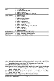
GA-EP45T-UD3P Motherboard - 12 - When two graphics cards are installing one PCI Express graphics card, be sure to install it in the PCIEX16_1 slot for Microsoft® ... Support for Ultra TPM Support for Time Repair Support for Q-Share Norton Internet Security (OEM version) Support for optimum performance. BIOS Unique Features Bundled Software Operating System Form Factor 2 x 8 Mbit flash Use of physical memory is installed, the actual memory size displayed will be...
GA-EP45T-UD3P Motherboard - 12 - When two graphics cards are installing one PCI Express graphics card, be sure to install it in the PCIEX16_1 slot for Microsoft® ... Support for Ultra TPM Support for Time Repair Support for Q-Share Norton Internet Security (OEM version) Support for optimum performance. BIOS Unique Features Bundled Software Operating System Form Factor 2 x 8 Mbit flash Use of physical memory is installed, the actual memory size displayed will be...
Manual
Page 16
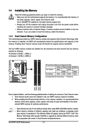
After the memory is installed, the BIOS will double the original memory bandwidth. DS/SS - - -...DDR3_2 Channel 1: DDR3_3, DDR3_4 Dual Channel Memory Configurations Table DDR3_1 DDR3_2 DDR3_3 DDR3_4 Two Modules DS/SS - - GA-EP45T-UD3P Motherboard - 16 - A memory module can only fit one direction. Enabling Dual Channel memory mode will automatically detect...cord from the power outlet before installing the memory in Dual Channel mode. 1. If you begin to GIGABYTE's website for optimum performance. • Each channel can be installed in only one memory module when ...
After the memory is installed, the BIOS will double the original memory bandwidth. DS/SS - - -...DDR3_2 Channel 1: DDR3_3, DDR3_4 Dual Channel Memory Configurations Table DDR3_1 DDR3_2 DDR3_3 DDR3_4 Two Modules DS/SS - - GA-EP45T-UD3P Motherboard - 16 - A memory module can only fit one direction. Enabling Dual Channel memory mode will automatically detect...cord from the power outlet before installing the memory in Dual Channel mode. 1. If you begin to GIGABYTE's website for optimum performance. • Each channel can be installed in only one memory module when ...

Manual
Page 18
... the slot. 4. Secure the card's metal bracket to the chassis back panel with the expansion card in the slot. 3. If necessary, go to BIOS Setup to correctly install your computer. Install the driver provided with a screw. 5. Remove the metal slot cover from the PCIEX8_1 slot: Press the white... PCI Express x16 Slot PCI Slot Follow the steps below to make any required BIOS changes for your card. Make sure the metal contacts on the slot and then lift the card straight out from the slot. GA-EP45T-UD3P Motherboard - 18 - • Removing the Card from the chassis back panel. 2....
... the slot. 4. Secure the card's metal bracket to the chassis back panel with the expansion card in the slot. 3. If necessary, go to BIOS Setup to correctly install your computer. Install the driver provided with a screw. 5. Remove the metal slot cover from the PCIEX8_1 slot: Press the white... PCI Express x16 Slot PCI Slot Follow the steps below to make any required BIOS changes for your card. Make sure the metal contacts on the slot and then lift the card straight out from the slot. GA-EP45T-UD3P Motherboard - 18 - • Removing the Card from the chassis back panel. 2....

Manual
Page 27
... detected at system startup. One single short beep will be heard if no problem is in S1 sleep state. If a problem is detected, the BIOS may differ by issuing a beep code. A front panel module mainly consists of power switch, reset switch, power LED, hard drive activity LED, ...make sure the wire assignments and the pin assignments are matched correctly. - 27 - When connecting your system using the power switch (refer to Chapter 2, "BIOS Setup," "Power Management Setup," for information about beep codes. • HD (Hard Drive Activity LED, Blue) Connects to the hard drive activity LED on...
... detected at system startup. One single short beep will be heard if no problem is in S1 sleep state. If a problem is detected, the BIOS may differ by issuing a beep code. A front panel module mainly consists of power switch, reset switch, power LED, hard drive activity LED, ...make sure the wire assignments and the pin assignments are matched correctly. - 27 - When connecting your system using the power switch (refer to Chapter 2, "BIOS Setup," "Power Management Setup," for information about beep codes. • HD (Hard Drive Activity LED, Blue) Connects to the hard drive activity LED on...

Manual
Page 32
...do so may cause damage to the motherboard. • After system restart, go to BIOS Setup to load factory defaults (select Load Optimized Defaults) or manually configure the BIOS settings (refer to Chapter 2, "BIOS Setup," for a few seconds. This function requires a chassis with chassis intrusion detection design... the two pins or use a metal object like a screwdriver to factory defaults. GA-EP45T-UD3P Motherboard - 32 - date information and BIOS configurations) and reset the CMOS values to touch the two pins for BIOS configurations). Pin No. To clear the CMOS values, place a jumper cap on...
...do so may cause damage to the motherboard. • After system restart, go to BIOS Setup to load factory defaults (select Load Optimized Defaults) or manually configure the BIOS settings (refer to Chapter 2, "BIOS Setup," for a few seconds. This function requires a chassis with chassis intrusion detection design... the two pins or use a metal object like a screwdriver to factory defaults. GA-EP45T-UD3P Motherboard - 32 - date information and BIOS configurations) and reset the CMOS values to touch the two pins for BIOS configurations). Pin No. To clear the CMOS values, place a jumper cap on...

Manual
Page 33
.... 4. Danger of explosion if the battery is replaced with an equivalent one minute. (Or use a metal object like a screwdriver to keep the values (such as BIOS configurations, date, and time information) in accordance with local environmental regulations. 23) PHASE LED The number of lighted LEDs indicates the CPU loading. Hardware Installation...
.... 4. Danger of explosion if the battery is replaced with an equivalent one minute. (Or use a metal object like a screwdriver to keep the values (such as BIOS configurations, date, and time information) in accordance with local environmental regulations. 23) PHASE LED The number of lighted LEDs indicates the CPU loading. Hardware Installation...

Manual
Page 35
... of the battery/clearing CMOS jumper in system malfunction. • BIOS will emit a beep code during system startup, saving system parameters and loading operating system, etc. To upgrade the BIOS, use either the GIGABYTE Q-Flash or @BIOS utility. • Q-Flash allows the user to clear the CMOS... values.) - 35 - Its major functions include conducting the Power-On Self-Test (POST) during the POST. BIOS includes a BIOS Setup program that you do ...
... of the battery/clearing CMOS jumper in system malfunction. • BIOS will emit a beep code during system startup, saving system parameters and loading operating system, etc. To upgrade the BIOS, use either the GIGABYTE Q-Flash or @BIOS utility. • Q-Flash allows the user to clear the CMOS... values.) - 35 - Its major functions include conducting the Power-On Self-Test (POST) during the POST. BIOS includes a BIOS Setup program that you do ...

Manual
Page 36
...startup, refer to the instructions on the Full Screen LOGO Show item on BIOS Setup settings. Motherboard Model BIOS Version EP45T-UD3P E12 . . . . : BIOS Setup : XpressRecovery2 : Boot Menu : Qflash 09/30/2008-P45-ICH10...order will directly boot from the device configured in Boot Menu is effective for subsequent access to enter BIOS Setup first. 2-1 Startup Screen The following screens may appear when the computer boots. A. To exit... access the Q-Flash utility directly without entering BIOS Setup. GA-EP45T-UD3P Motherboard - 36 - The LOGO Screen (Default) Function Keys B.
...startup, refer to the instructions on the Full Screen LOGO Show item on BIOS Setup settings. Motherboard Model BIOS Version EP45T-UD3P E12 . . . . : BIOS Setup : XpressRecovery2 : Boot Menu : Qflash 09/30/2008-P45-ICH10...order will directly boot from the device configured in Boot Menu is effective for subsequent access to enter BIOS Setup first. 2-1 Startup Screen The following screens may appear when the computer boots. A. To exit... access the Q-Flash utility directly without entering BIOS Setup. GA-EP45T-UD3P Motherboard - 36 - The LOGO Screen (Default) Function Keys B.

Manual
Page 37
...; Security Chip Configuration ESC: Quit F8: Q-Flash Select Item F10: Save & Exit Setup F11: Save CMOS to BIOS F12: Load CMOS from BIOS Change CPU's Clock & Voltage BIOS Setup Program Function Keys Move the selection bar to select an item Execute command or enter the submenu Main Menu: Exit...exit the help screen (General Help) of the Main Menu. 2-2 The Main Menu Once you want in a submenu, press to display a help screen. BIOS Setup Submenu Help While in the Main Menu or a submenu, press + to access more advanced options. • When the system is in the Item...
...; Security Chip Configuration ESC: Quit F8: Q-Flash Select Item F10: Save & Exit Setup F11: Save CMOS to BIOS F12: Load CMOS from BIOS Change CPU's Clock & Voltage BIOS Setup Program Function Keys Move the selection bar to select an item Execute command or enter the submenu Main Menu: Exit...exit the help screen (General Help) of the Main Menu. 2-2 The Main Menu Once you want in a submenu, press to display a help screen. BIOS Setup Submenu Help While in the Main Menu or a submenu, press + to access more advanced options. • When the system is in the Item...


