Manual
Page 3
... updating motherboard BIOS, drivers, or when looking for technical information. is exclusively licensed to assist in this manual are legally registered to use of this : "REV: X.X." For example, "REV: 1.0" means the revision of this manual is protected by copyright laws and is 1.0. Disclaimer Information in any form or by GIGABYTE without GIGABYTE's prior...
... updating motherboard BIOS, drivers, or when looking for technical information. is exclusively licensed to assist in this manual are legally registered to use of this : "REV: X.X." For example, "REV: 1.0" means the revision of this manual is protected by copyright laws and is 1.0. Disclaimer Information in any form or by GIGABYTE without GIGABYTE's prior...
Manual
Page 4
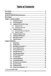
Table of Contents Box Contents ...6 OptionalItems ...6 GA-EP45T-DS3R/DS3 Motherboard Layout 7 Block Diagram ...8 Chapter 1 Hardware Installation 9 1-1 Installation Precautions 9 1-2 Product Specifications 10 1-3 Installing the CPU and CPU Cooler ... the SATA Bracket 19 1-7 Back Panel Connectors 20 1-8 Internal Connectors 22 Chapter 2 BIOS Setup 35 2-1 Startup Screen 36 2-2 The Main Menu 37 2-3 MB Intelligent Tweaker(M.I.T 39 2-4 Standard CMOS Features 46 2-5 Advanced BIOS Features 48 2-6 IntegratedPeripherals 51 2-7 Power Management Setup 55 2-8 PnP/PCI Configurations 57 ...
Table of Contents Box Contents ...6 OptionalItems ...6 GA-EP45T-DS3R/DS3 Motherboard Layout 7 Block Diagram ...8 Chapter 1 Hardware Installation 9 1-1 Installation Precautions 9 1-2 Product Specifications 10 1-3 Installing the CPU and CPU Cooler ... the SATA Bracket 19 1-7 Back Panel Connectors 20 1-8 Internal Connectors 22 Chapter 2 BIOS Setup 35 2-1 Startup Screen 36 2-2 The Main Menu 37 2-3 MB Intelligent Tweaker(M.I.T 39 2-4 Standard CMOS Features 46 2-5 Advanced BIOS Features 48 2-6 IntegratedPeripherals 51 2-7 Power Management Setup 55 2-8 PnP/PCI Configurations 57 ...

Manual
Page 5
...64 3-4 Contact ...65 3-5 System ...65 3-6 Download Center 66 Chapter 4 Unique Features 67 4-1 Xpress Recovery2 67 4-2 BIOS Update Utilities 72 4-2-1 Updating the BIOS with the Q-Flash Utility 72 4-2-2 Updating the BIOS with the @BIOS Utility 75 4-3 EasyTune 6 ...76 4-4 Dynamic Energy Saver Advanced 77 4-5 Ultra TPM (Note 79 4-6 Q-Share ...80... the Sound Recorder 105 5-3 Troubleshooting 106 5-3-1 Frequently Asked Questions 106 5-3-2 Troubleshooting Procedure 107 Regulatory Statements 109 Only for GA-EP45T-DS3R. (Note) This feature is optional due to different regional policy. - 5 -
...64 3-4 Contact ...65 3-5 System ...65 3-6 Download Center 66 Chapter 4 Unique Features 67 4-1 Xpress Recovery2 67 4-2 BIOS Update Utilities 72 4-2-1 Updating the BIOS with the Q-Flash Utility 72 4-2-2 Updating the BIOS with the @BIOS Utility 75 4-3 EasyTune 6 ...76 4-4 Dynamic Energy Saver Advanced 77 4-5 Ultra TPM (Note 79 4-6 Q-Share ...80... the Sound Recorder 105 5-3 Troubleshooting 106 5-3-1 Frequently Asked Questions 106 5-3-2 Troubleshooting Procedure 107 Regulatory Statements 109 Only for GA-EP45T-DS3R. (Note) This feature is optional due to different regional policy. - 5 -
Manual
Page 8
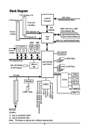
Only for GA-EP45T-DS3R. Block Diagram 1 PCI Express x16 1 PCI Express x8 PCIe CLK (100 MHz) PCIe CLK (100 MHz) PCI Express x16 PCI Express x8 ...800 MHz Intel® P45 Dual Channel Memory MCH CLK (400/333/266/200 MHz) PCIe CLK (100 MHz) RTL RTL 8111C 8111C Dual BIOS x1 x1 x1 PCI Express Bus ATA-133/100/66/ 33 IDE Channel x1 x1 JMicron 368 Intel® ICH10R Intel® ICH10 6 .../Subwoofer Speaker Out Side Speaker Out MIC Line-Out Line-In SPDIF In SPDIF Out 2 PCI PCI CLK (33 MHz) Only for GA-EP45T-DS3. (Note) This feature is optional due to different regional policy. - 8 -
Only for GA-EP45T-DS3R. Block Diagram 1 PCI Express x16 1 PCI Express x8 PCIe CLK (100 MHz) PCIe CLK (100 MHz) PCI Express x16 PCI Express x8 ...800 MHz Intel® P45 Dual Channel Memory MCH CLK (400/333/266/200 MHz) PCIe CLK (100 MHz) RTL RTL 8111C 8111C Dual BIOS x1 x1 x1 PCI Express Bus ATA-133/100/66/ 33 IDE Channel x1 x1 JMicron 368 Intel® ICH10R Intel® ICH10 6 .../Subwoofer Speaker Out Side Speaker Out MIC Line-Out Line-In SPDIF In SPDIF Out 2 PCI PCI CLK (33 MHz) Only for GA-EP45T-DS3. (Note) This feature is optional due to different regional policy. - 8 -
Manual
Page 12
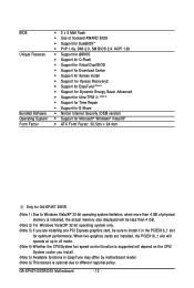
GA-EP45T-DS3R/DS3 Motherboard - 12 - BIOS Unique Features Bundled Software Operating System Form Factor Š 2 x 8 Mbit flash Š Use of physical memory is optional due to x8 mode. (Note 4) Whether the ... Š Norton Internet Security (OEM version) Š Support for Microsoft® Windows® Vista/XP Š ATX Form Factor; 30.5cm x 24.4cm Only for GA-EP45T-DS3R. (Note 1) Due to Windows Vista/XP 32-bit operating system limitation, when more than 4 GB. (Note 2) For Windows Vista/XP 32-bit operating system...
GA-EP45T-DS3R/DS3 Motherboard - 12 - BIOS Unique Features Bundled Software Operating System Form Factor Š 2 x 8 Mbit flash Š Use of physical memory is optional due to x8 mode. (Note 4) Whether the ... Š Norton Internet Security (OEM version) Š Support for Microsoft® Windows® Vista/XP Š ATX Form Factor; 30.5cm x 24.4cm Only for GA-EP45T-DS3R. (Note 1) Due to Windows Vista/XP 32-bit operating system limitation, when more than 4 GB. (Note 2) For Windows Vista/XP 32-bit operating system...

Manual
Page 16
...recommended that memory of different capacity and chips are installed, a message which says memory is installed, the BIOS will double the original memory bandwidth. 1-4 Installing the Memory Read the following guidelines before you are unable... turn off the computer and unplug the power cord from the power outlet before installing the memory to GIGABYTE's website for optimum performance. • Each channel can be installed in Dual Channel mode/performance. After... chips be populated and remain in only one direction. GA-EP45T-DS3R/DS3 Motherboard - 16 - It is installed. 2.
...recommended that memory of different capacity and chips are installed, a message which says memory is installed, the BIOS will double the original memory bandwidth. 1-4 Installing the Memory Read the following guidelines before you are unable... turn off the computer and unplug the power cord from the power outlet before installing the memory to GIGABYTE's website for optimum performance. • Each channel can be installed in Dual Channel mode/performance. After... chips be populated and remain in only one direction. GA-EP45T-DS3R/DS3 Motherboard - 16 - It is installed. 2.

Manual
Page 18
.... If necessary, go to BIOS Setup to correctly install your computer. Make sure the card is securely seated in the slot and does not rock. • Removing the Card from the PCIEX16_1 slot: Gently push back on the lever on your expansion card in the slot. 3. GA-EP45T-DS3R/DS3 Motherboard - 18 - • Removing... your expansion card(s). 7. PCI Express x1 Slot PCI Express x16 Slot PCI Express x8 Slot PCI Slot Follow the steps below to make any required BIOS changes for your card.
.... If necessary, go to BIOS Setup to correctly install your computer. Make sure the card is securely seated in the slot and does not rock. • Removing the Card from the PCIEX16_1 slot: Gently push back on the lever on your expansion card in the slot. 3. GA-EP45T-DS3R/DS3 Motherboard - 18 - • Removing... your expansion card(s). 7. PCI Express x1 Slot PCI Express x16 Slot PCI Express x8 Slot PCI Slot Follow the steps below to make any required BIOS changes for your card.
Manual
Page 27
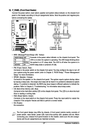
... of power switch, reset switch, power LED, hard drive activity LED, speaker and etc. When connecting your system using the power switch (refer to Chapter 2, "BIOS Setup," "Power Management Setup," for information about beep codes. • HD (Hard Drive Activity LED, Blue) Connects to this header according to the reset switch... matched correctly. - 27 - Note the positive and negative pins before connecting the cables. The S0 On LED is on when the system is detected, the BIOS may differ by issuing a beep code.
... of power switch, reset switch, power LED, hard drive activity LED, speaker and etc. When connecting your system using the power switch (refer to Chapter 2, "BIOS Setup," "Power Management Setup," for information about beep codes. • HD (Hard Drive Activity LED, Blue) Connects to this header according to the reset switch... matched correctly. - 27 - Note the positive and negative pins before connecting the cables. The S0 On LED is on when the system is detected, the BIOS may differ by issuing a beep code.

Manual
Page 32
GA-EP45T-DS3R/DS3 Motherboard - 32 - Pin No. Open: Normal Short: Clear CMOS Values • Always turn off your computer, be sure to remove the jumper cap from the ... to factory defaults. Failure to do so may cause damage to the motherboard. • After system restart, go to BIOS Setup to load factory defaults (select Load Optimized Defaults) or manually configure the BIOS settings (refer to clear the CMOS values (e.g. This function requires a chassis with chassis intrusion detection design. To clear...
GA-EP45T-DS3R/DS3 Motherboard - 32 - Pin No. Open: Normal Short: Clear CMOS Values • Always turn off your computer, be sure to remove the jumper cap from the ... to factory defaults. Failure to do so may cause damage to the motherboard. • After system restart, go to BIOS Setup to load factory defaults (select Load Optimized Defaults) or manually configure the BIOS settings (refer to clear the CMOS values (e.g. This function requires a chassis with chassis intrusion detection design. To clear...

Manual
Page 33
... the battery is turned off your computer and unplug the power cord. 2. 21) BAT (BATTERY) The battery provides power to keep the values (such as BIOS configurations, date, and time information) in the CMOS when the computer is replaced with an incorrect model. • Contact the place of purchase or local...
... the battery is turned off your computer and unplug the power cord. 2. 21) BAT (BATTERY) The battery provides power to keep the values (such as BIOS configurations, date, and time information) in the CMOS when the computer is replaced with an incorrect model. • Contact the place of purchase or local...

Manual
Page 35
... the key during the POST when the power is a Windows-based utility that you can press + in the CMOS on using the current version of BIOS, it with caution. To upgrade the BIOS, use either the GIGABYTE Q-Flash or @BIOS utility. • Q-Flash allows the user to quickly and easily upgrade or back up...
... the key during the POST when the power is a Windows-based utility that you can press + in the CMOS on using the current version of BIOS, it with caution. To upgrade the BIOS, use either the GIGABYTE Q-Flash or @BIOS utility. • Q-Flash allows the user to quickly and easily upgrade or back up...

Manual
Page 36
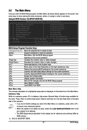
... The setting in Boot Menu. Motherboard Model BIOS Version EP45T-DS3R E6 . . . . : BIOS Setup : XpressRecovery2 : Boot Menu : Qflash 05/28/2008-P45-ICH10-7A89PG0LC-00 Function Keys Function Keys: : POST Screen Press the key to show the BIOS POST screen at system startup, refer to ...restart, the device boot order will directly boot from the device configured in Boot Menu is effective for subsequent access to enter BIOS Setup first. GA-EP45T-DS3R/DS3 Motherboard - 36 - 2-1 Startup Screen The following screens may appear when the computer boots. For more information, refer to ...
... The setting in Boot Menu. Motherboard Model BIOS Version EP45T-DS3R E6 . . . . : BIOS Setup : XpressRecovery2 : Boot Menu : Qflash 05/28/2008-P45-ICH10-7A89PG0LC-00 Function Keys Function Keys: : POST Screen Press the key to show the BIOS POST screen at system startup, refer to ...restart, the device boot order will directly boot from the device configured in Boot Menu is effective for subsequent access to enter BIOS Setup first. GA-EP45T-DS3R/DS3 Motherboard - 36 - 2-1 Startup Screen The following screens may appear when the computer boots. For more information, refer to ...
Manual
Page 37
... arrow keys to move among the items and press to accept or enter a sub-menu. (Sample BIOS Version: GA-EP45T-DS3R E6) CMOS Setup Utility-Copyright (C) 1984-2008 Award Software ` MB Intelligent Tweaker(M.I.T.) ` Standard CMOS Features ` Advanced BIOS Features ` Integrated Peripherals ` Power Management Setup ` PnP/PCI Configurations ` PC Health Status ` ESC: Quit F8: Q-Flash...
... arrow keys to move among the items and press to accept or enter a sub-menu. (Sample BIOS Version: GA-EP45T-DS3R E6) CMOS Setup Utility-Copyright (C) 1984-2008 Award Software ` MB Intelligent Tweaker(M.I.T.) ` Standard CMOS Features ` Advanced BIOS Features ` Integrated Peripherals ` Power Management Setup ` PnP/PCI Configurations ` PC Health Status ` ESC: Quit F8: Q-Flash...
Manual
Page 38
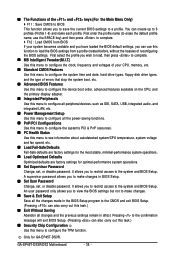
..., without the hassles of the and keys (For the Main Menu Only) ` F11 : Save CMOS to BIOS This function allows you to the system and BIOS Setup. You can also carry out this menu to a profile. GA-EP45T-DS3R/DS3 Motherboard - 38 - Only for optimal-performance system operations. „ Set Supervisor Password Change, set , or...
..., without the hassles of the and keys (For the Main Menu Only) ` F11 : Save CMOS to BIOS This function allows you to the system and BIOS Setup. You can also carry out this menu to a profile. GA-EP45T-DS3R/DS3 Motherboard - 38 - Only for optimal-performance system operations. „ Set Supervisor Password Change, set , or...

Manual
Page 39
... appears only if you install a CPU that supports this feature. (Note 2) This item appears only if you install a memory module that supports this feature. - 39 - BIOS Setup
... appears only if you install a CPU that supports this feature. (Note 2) This item appears only if you install a memory module that supports this feature. - 39 - BIOS Setup
Manual
Page 40
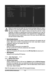
... Frequency Displays the current operating CPU frequency. ******** Clock Chip Control Standard Clock Control CPU Host Clock Control Enables or disables the control of these components. GA-EP45T-DS3R/DS3 Motherboard - 40 - CMOS Setup Utility-Copyright (C) 1984-2008 Award Software MB Intelligent Tweaker(M.I.T.) MCH Core MCH Reference MCH/DRAM Reference ICH I/O >>> DRAM DRAM Voltage... after overclocking, please wait for 20 seconds to allow the CPU Host Frequency item below to automatically set in damage to boot. Auto allows the BIOS to be configurable. Ch-B Data VRef.
... Frequency Displays the current operating CPU frequency. ******** Clock Chip Control Standard Clock Control CPU Host Clock Control Enables or disables the control of these components. GA-EP45T-DS3R/DS3 Motherboard - 40 - CMOS Setup Utility-Copyright (C) 1984-2008 Award Software MB Intelligent Tweaker(M.I.T.) MCH Core MCH Reference MCH/DRAM Reference ICH I/O >>> DRAM DRAM Voltage... after overclocking, please wait for 20 seconds to allow the CPU Host Frequency item below to automatically set in damage to boot. Auto allows the BIOS to be configurable. Ch-B Data VRef.

Manual
Page 41
... the use of C.I .A.2) is highly dependent on CPU loading. Warning: Before using C.I .A.2 allows your system bus to be set in accordance with the CPU specifications. BIOS Setup For an 800 MHz FSB CPU, set this item to 266 MHz. C.I .A.2, please first verify the overclocking capability of 5 preset states. This item is...
... the use of C.I .A.2) is highly dependent on CPU loading. Warning: Before using C.I .A.2 allows your system bus to be set in accordance with the CPU specifications. BIOS Setup For an 800 MHz FSB CPU, set this item to 266 MHz. C.I .A.2, please first verify the overclocking capability of 5 preset states. This item is...

Manual
Page 42
... the system operate at its basic performance level. Disabled Disables this feature. Options for adjusting memory multiplier below to be configurable. GA-EP45T-DS3R/DS3 Motherboard - 42 - CPU Clock Skew Allows you to set the system memory multiplier. Turbo Lets the system operate at its ... Manual allows all DRAM timing control items below may differ according to the fixed frequency. Extreme Memory Profile (X.M.P.) (Note) Allows the BIOS to read the SPD data on CPU FSB and the (G)MCH Frequency Latch settings. Profile2 Uses Profile 2 settings. (G)MCH Frequency Latch...
... the system operate at its basic performance level. Disabled Disables this feature. Options for adjusting memory multiplier below to be configurable. GA-EP45T-DS3R/DS3 Motherboard - 42 - CPU Clock Skew Allows you to set the system memory multiplier. Turbo Lets the system operate at its ... Manual allows all DRAM timing control items below may differ according to the fixed frequency. Extreme Memory Profile (X.M.P.) (Note) Allows the BIOS to read the SPD data on CPU FSB and the (G)MCH Frequency Latch settings. Profile2 Uses Profile 2 settings. (G)MCH Frequency Latch...

Manual
Page 43
...`` KLJI: Move Enter: Select F5: Previous Values +/-/PU/PD: Value F10: Save F6: Fail-Safe Defaults ESC: Exit F1: General Help F7: Optimized Defaults - 43 - BIOS Setup tRAS Options are : Auto (default), 1~15. >>>>> Standard Timing Control CAS Latency Time Options are : Auto (default), 1~15. tRP Options are : Auto (default), 4~11...
...`` KLJI: Move Enter: Select F5: Previous Values +/-/PU/PD: Value F10: Save F6: Fail-Safe Defaults ESC: Exit F1: General Help F7: Optimized Defaults - 43 - BIOS Setup tRAS Options are : Auto (default), 1~15. >>>>> Standard Timing Control CAS Latency Time Options are : Auto (default), 1~15. tRP Options are : Auto (default), 4~11...

Manual
Page 45
... PLL The default is Auto. ******** - 45 - The default is Auto. CPU Termination The default is Auto. Trd2wr(Same/Diff Rank) Options are : Auto (default), 1~15. BIOS Setup Ch-B Data VRef. Trd2rd(Different Rank) Options are : Auto (default), 1~15. ICH I/O The default is Auto. >>> DRAM DRAM Voltage The default is Auto. Twr2wr...
... PLL The default is Auto. ******** - 45 - The default is Auto. CPU Termination The default is Auto. Trd2wr(Same/Diff Rank) Options are : Auto (default), 1~15. BIOS Setup Ch-B Data VRef. Trd2rd(Different Rank) Options are : Auto (default), 1~15. ICH I/O The default is Auto. >>> DRAM DRAM Voltage The default is Auto. Twr2wr...


