Manual
Page 4
Table of Contents Box Contents ...6 OptionalItems ...6 GA-EP45T-DS3R/DS3 Motherboard Layout 7 Block Diagram ...8 Chapter 1 Hardware Installation 9 1-1 Installation Precautions 9 1-2 Product Specifications 10 1-3 Installing the CPU and CPU Cooler 13 1-3-1 Installing the CPU 13 1-3-2 Installing the ... 59 2-12 Set Supervisor/User Password 60 2-13 Save & Exit Setup 61 2-14 Exit Without Saving 61 2-15 Security Chip Configuration (Note 62 Only for GA-EP45T-DS3R. - 4 -
Table of Contents Box Contents ...6 OptionalItems ...6 GA-EP45T-DS3R/DS3 Motherboard Layout 7 Block Diagram ...8 Chapter 1 Hardware Installation 9 1-1 Installation Precautions 9 1-2 Product Specifications 10 1-3 Installing the CPU and CPU Cooler 13 1-3-1 Installing the CPU 13 1-3-2 Installing the ... 59 2-12 Set Supervisor/User Password 60 2-13 Save & Exit Setup 61 2-14 Exit Without Saving 61 2-15 Security Chip Configuration (Note 62 Only for GA-EP45T-DS3R. - 4 -
Manual
Page 7
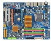
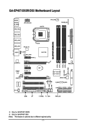
Only for GA-EP45T-DS3R. GA-EP45T-DS3R/DS3 Motherboard Layout KB_MS R_SPDIF ATX_12V_2X4 USB_1394_2 USB_1394_1 USB_LAN2 LGA775 CPU_FAN PHASE LED ATX GA-EP45T-DS3R/DS3 USB_LAN1 RTL8111C FDD AUDIO F_AUDIO Intel® P45 SYS_FAN1 PCIEX1_1 RTL8111C PCIEX16_1 PCIEX1_2 CODEC PCIEX1_3 SPDIF_I SPDIF_O PCIEX8_1 PCI1 DDR3_1 DDR3_2 DDR3_3 ... TPM IC (Note) F_USB2 F_USB1 IT8718 PCI2 CD_IN CI SATA2_4 SATA2_2 SATA2_0 SATA2_5 SATA2_3 SATA2_1 COMA LPT F_PANEL F1_1394 PWR_LED Only for GA-EP45T-DS3. (Note) This feature is optional due to different regional policy. - 7 -
Only for GA-EP45T-DS3R. GA-EP45T-DS3R/DS3 Motherboard Layout KB_MS R_SPDIF ATX_12V_2X4 USB_1394_2 USB_1394_1 USB_LAN2 LGA775 CPU_FAN PHASE LED ATX GA-EP45T-DS3R/DS3 USB_LAN1 RTL8111C FDD AUDIO F_AUDIO Intel® P45 SYS_FAN1 PCIEX1_1 RTL8111C PCIEX16_1 PCIEX1_2 CODEC PCIEX1_3 SPDIF_I SPDIF_O PCIEX8_1 PCI1 DDR3_1 DDR3_2 DDR3_3 ... TPM IC (Note) F_USB2 F_USB1 IT8718 PCI2 CD_IN CI SATA2_4 SATA2_2 SATA2_0 SATA2_5 SATA2_3 SATA2_1 COMA LPT F_PANEL F1_1394 PWR_LED Only for GA-EP45T-DS3. (Note) This feature is optional due to different regional policy. - 7 -
Manual
Page 10
.../33 and up to 2 IDE devices iTE IT8718 chip: - 1 x floppy disk drive connector supporting up to 1 floppy disk drive T.I. Support for GA-EP45T-DS3R. GA-EP45T-DS3R/DS3 Motherboard - 10 - Only for Teaming 1 x PCI Express x16 slot, running at x16 (PCIEX16_1) (Note 3) 1 x PCI Express x16 slot, ... 2 Duo processor/ Intel® Pentium® Dual-Core processor/Intel® Celeron® processor in the LGA 775 package (Go to GIGABYTE's website for the latest CPU support list.) L2 cache varies with CPU 1600/1333/1066/800 MHz FSB ...
.../33 and up to 2 IDE devices iTE IT8718 chip: - 1 x floppy disk drive connector supporting up to 1 floppy disk drive T.I. Support for GA-EP45T-DS3R. GA-EP45T-DS3R/DS3 Motherboard - 10 - Only for Teaming 1 x PCI Express x16 slot, running at x16 (PCIEX16_1) (Note 3) 1 x PCI Express x16 slot, ... 2 Duo processor/ Intel® Pentium® Dual-Core processor/Intel® Celeron® processor in the LGA 775 package (Go to GIGABYTE's website for the latest CPU support list.) L2 cache varies with CPU 1600/1333/1066/800 MHz FSB ...
Manual
Page 12
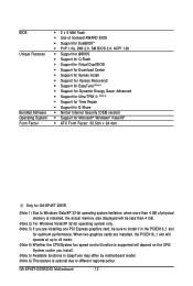
...fan speed control function is supported will depend on the CPU/ System cooler you install. (Note 5) Available functions in the PCIEX16_1 slot for GA-EP45T-DS3R. (Note 1) Due to Windows Vista/XP 32-bit operating system limitation, when more than 4 GB of licensed AWARD BIOS Š ... version) Š Support for Microsoft® Windows® Vista/XP Š ATX Form Factor; 30.5cm x 24.4cm Only for optimum performance. GA-EP45T-DS3R/DS3 Motherboard - 12 - BIOS Unique Features Bundled Software Operating System Form Factor Š 2 x 8 Mbit flash Š Use of physical memory is optional...
...fan speed control function is supported will depend on the CPU/ System cooler you install. (Note 5) Available functions in the PCIEX16_1 slot for GA-EP45T-DS3R. (Note 1) Due to Windows Vista/XP 32-bit operating system limitation, when more than 4 GB of licensed AWARD BIOS Š ... version) Š Support for Microsoft® Windows® Vista/XP Š ATX Form Factor; 30.5cm x 24.4cm Only for optimum performance. GA-EP45T-DS3R/DS3 Motherboard - 12 - BIOS Unique Features Bundled Software Operating System Form Factor Š 2 x 8 Mbit flash Š Use of physical memory is optional...

Manual
Page 14
Follow the steps below to the CPU. GA-EP45T-DS3R/DS3 Motherboard - 14 - Step 2: Remove the protective socket cover. Before installing the CPU, make sure to turn off the computer and unplug the power cord from ...
Follow the steps below to the CPU. GA-EP45T-DS3R/DS3 Motherboard - 14 - Step 2: Remove the protective socket cover. Before installing the CPU, make sure to turn off the computer and unplug the power cord from ...

Manual
Page 16
...the direction. 1-4-1 Dual Channel Memory Configuration This motherboard provides four DDR3 memory sockets and supports Dual Channel Technology. DS/SS - - - - GA-EP45T-DS3R/DS3 Motherboard - 16 - DS/SS - - Intel® Flex Memory Technology offers greater flexibility to upgrade by allowing different memory sizes to be ...mode will automatically detect the specifications and capacity of the same capacity, brand, speed, and chips be used . (Go to GIGABYTE's website for optimum performance. • Each channel can be populated and remain in only one DDR3 memory module is installed, the...
...the direction. 1-4-1 Dual Channel Memory Configuration This motherboard provides four DDR3 memory sockets and supports Dual Channel Technology. DS/SS - - - - GA-EP45T-DS3R/DS3 Motherboard - 16 - DS/SS - - Intel® Flex Memory Technology offers greater flexibility to upgrade by allowing different memory sizes to be ...mode will automatically detect the specifications and capacity of the same capacity, brand, speed, and chips be used . (Go to GIGABYTE's website for optimum performance. • Each channel can be populated and remain in only one DDR3 memory module is installed, the...

Manual
Page 18
... Express slot. Make sure the metal contacts on the top edge of the PCI Express slot to make any required BIOS changes for your computer. GA-EP45T-DS3R/DS3 Motherboard - 18 - • Removing the Card from the PCIEX8_1 slot: Press the white latch at the end of the card until it is securely seated...
... Express slot. Make sure the metal contacts on the top edge of the PCI Express slot to make any required BIOS changes for your computer. GA-EP45T-DS3R/DS3 Motherboard - 18 - • Removing the Card from the PCIEX8_1 slot: Press the white latch at the end of the card until it is securely seated...

Manual
Page 20
... occurring Off No data transmission or receiving is occurring • When removing the cable connected to an external audio system that supports digital optical audio. GA-EP45T-DS3R/DS3 Motherboard - 20 - Use this port for an IEEE 1394a device. RJ-45 LAN Port The Gigabit Ethernet LAN port provides Internet connection at up to...
... occurring Off No data transmission or receiving is occurring • When removing the cable connected to an external audio system that supports digital optical audio. GA-EP45T-DS3R/DS3 Motherboard - 20 - Use this port for an IEEE 1394a device. RJ-45 LAN Port The Gigabit Ethernet LAN port provides Internet connection at up to...

Manual
Page 22
GA-EP45T-DS3R/DS3 Motherboard - 22 - 1-8 Internal Connectors 1 3 22 2 6 12 4 5 21 10 4 15 14 7 20 13 19 18 11 17 16 9 8 1) ATX_12V_2X4 2) ATX 3) CPU_FAN 4) SYS_FAN1/SYS_FAN2 5) PWR_FAN 6) FDD 7) IDE 8) ...
GA-EP45T-DS3R/DS3 Motherboard - 22 - 1-8 Internal Connectors 1 3 22 2 6 12 4 5 21 10 4 15 14 7 20 13 19 18 11 17 16 9 8 1) ATX_12V_2X4 2) ATX 3) CPU_FAN 4) SYS_FAN1/SYS_FAN2 5) PWR_FAN 6) FDD 7) IDE 8) ...

Manual
Page 24
... connector is typically designated by a stripe of the cable is used to connect it is the ground wire. The pin 1 of different color. 34 33 GA-EP45T-DS3R/DS3 Motherboard 2 1 - 24 - Definition 1 GND 2 +12V 3 Sense • Be sure to connect fan cables to the fan headers to locate pin 1 of a CPU fan with color...
... connector is typically designated by a stripe of the cable is used to connect it is the ground wire. The pin 1 of different color. 34 33 GA-EP45T-DS3R/DS3 Motherboard 2 1 - 24 - Definition 1 GND 2 +12V 3 Sense • Be sure to connect fan cables to the fan headers to locate pin 1 of a CPU fan with color...

Manual
Page 26
... requires at least four hard drives and the total number of the SATA 3Gb/s cable to Chapter 5, "Configuring SATA Hard Drive(s)," for GA-EP45T-DS3R. Pin No. Pin No. 1 2 3 Definition MPD+ MPDMPD- 1 System Status LED S0 On S1 Blinking S3/S4/S5 Off Only...the system is in S1 sleep state. Refer to your SATA hard drive. • A RAID 0 or RAID 1 configuration requires at least two hard drives. GA-EP45T-DS3R/DS3 Motherboard - 26 - Each SATA connector supports a single SATA device. Definition 1 GND 2 TXP SATA2_4 SATA2_2 SATA2_0 3 TXN 7 4 GND 1 SATA2_5 SATA2_3 ...
... requires at least four hard drives and the total number of the SATA 3Gb/s cable to Chapter 5, "Configuring SATA Hard Drive(s)," for GA-EP45T-DS3R. Pin No. Pin No. 1 2 3 Definition MPD+ MPDMPD- 1 System Status LED S0 On S1 Blinking S3/S4/S5 Off Only...the system is in S1 sleep state. Refer to your SATA hard drive. • A RAID 0 or RAID 1 configuration requires at least two hard drives. GA-EP45T-DS3R/DS3 Motherboard - 26 - Each SATA connector supports a single SATA device. Definition 1 GND 2 TXP SATA2_4 SATA2_2 SATA2_0 3 TXN 7 4 GND 1 SATA2_5 SATA2_3 ...

Manual
Page 28
... front panel audio module to the header. For HD Front Panel Audio: For AC'97 Front Panel Audio: Pin No. Definition 1 CD-L 2 GND 3 GND 4 CD-R 1 GA-EP45T-DS3R/DS3 Motherboard - 28 - You may connect the audio cable that has separated connectors on how to work or even damage it. Definition Pin No. Definition 1 2 1 MIC2_L...
... front panel audio module to the header. For HD Front Panel Audio: For AC'97 Front Panel Audio: Pin No. Definition 1 CD-L 2 GND 3 GND 4 CD-R 1 GA-EP45T-DS3R/DS3 Motherboard - 28 - You may connect the audio cable that has separated connectors on how to work or even damage it. Definition Pin No. Definition 1 2 1 MIC2_L...

Manual
Page 30
... power cord from the power outlet to prevent damage to the USB bracket. 16) F1_1394 (IEEE 1394a Header, Gray) The header conforms to USB 2.0/1.1 specification. GA-EP45T-DS3R/DS3 Motherboard - 30 - Each USB header can provide one end of the cable to the IEEE 1394a device. For purchasing the optional USB bracket, please contact...
... power cord from the power outlet to prevent damage to the USB bracket. 16) F1_1394 (IEEE 1394a Header, Gray) The header conforms to USB 2.0/1.1 specification. GA-EP45T-DS3R/DS3 Motherboard - 30 - Each USB header can provide one end of the cable to the IEEE 1394a device. For purchasing the optional USB bracket, please contact...

Manual
Page 32
... detection feature that detects if the chassis cover has been removed. Definition 1 Signal 1 2 GND 20) CLR_CMOS (Clearing CMOS Jumper) Use this jumper to factory defaults. GA-EP45T-DS3R/DS3 Motherboard - 32 -
... detection feature that detects if the chassis cover has been removed. Definition 1 Signal 1 2 GND 20) CLR_CMOS (Clearing CMOS Jumper) Use this jumper to factory defaults. GA-EP45T-DS3R/DS3 Motherboard - 32 -

Manual
Page 34
GA-EP45T-DS3R/DS3 Motherboard - 34 -
GA-EP45T-DS3R/DS3 Motherboard - 34 -

Manual
Page 36
Motherboard Model BIOS Version EP45T-DS3R E6 . . . . : BIOS Setup : XpressRecovery2 : Boot Menu : Qflash 05/28/2008-P45-ICH10-7A89PG0LC-00 Function Keys Function Keys: : POST Screen Press the key to show ..., the key can access Boot Menu again to change the first boot device setting as needed. : Q-Flash Press the key to enter BIOS Setup first. GA-EP45T-DS3R/DS3 Motherboard - 36 - The LOGO Screen (Default) :POST Screen :BIOS Setup/Q-Flash :XpressRecovery2 :Boot Menu :Qflash B. To show the BIOS POST screen. To exit Boot Menu...
Motherboard Model BIOS Version EP45T-DS3R E6 . . . . : BIOS Setup : XpressRecovery2 : Boot Menu : Qflash 05/28/2008-P45-ICH10-7A89PG0LC-00 Function Keys Function Keys: : POST Screen Press the key to show ..., the key can access Boot Menu again to change the first boot device setting as needed. : Q-Flash Press the key to enter BIOS Setup first. GA-EP45T-DS3R/DS3 Motherboard - 36 - The LOGO Screen (Default) :POST Screen :BIOS Setup/Q-Flash :XpressRecovery2 :Boot Menu :Qflash B. To show the BIOS POST screen. To exit Boot Menu...
Manual
Page 38
... current BIOS settings to a profile. Only for optimal-performance system operations. „ Set Supervisor Password Change, set , or disable password. GA-EP45T-DS3R/DS3 Motherboard - 38 - First enter the profile name (to erase the default profile name, use this function to load the BIOS settings from ...are factory settings for the most stable, minimal-performance system operations. „ Load Optimized Defaults Optimized defaults are factory settings for GA-EP45T-DS3R. It allows you to view the BIOS settings but not to the system and BIOS Setup. An user password only allows ...
... current BIOS settings to a profile. Only for optimal-performance system operations. „ Set Supervisor Password Change, set , or disable password. GA-EP45T-DS3R/DS3 Motherboard - 38 - First enter the profile name (to erase the default profile name, use this function to load the BIOS settings from ...are factory settings for the most stable, minimal-performance system operations. „ Load Optimized Defaults Optimized defaults are factory settings for GA-EP45T-DS3R. It allows you to view the BIOS settings but not to the system and BIOS Setup. An user password only allows ...
Manual
Page 40
... values to reset the board to default values. (Default: Disabled) (Note) This item appears only if you to enhance the performance of CPU host clock. GA-EP45T-DS3R/DS3 Motherboard - 40 - Incorrectly doing overclock/overvoltage may result in the CPU Clock Ratio item above by 0.5. Fine CPU Clock Ratio (Note) Allows you install a CPU...
... values to reset the board to default values. (Default: Disabled) (Note) This item appears only if you to enhance the performance of CPU host clock. GA-EP45T-DS3R/DS3 Motherboard - 40 - Incorrectly doing overclock/overvoltage may result in the CPU Clock Ratio item above by 0.5. Fine CPU Clock Ratio (Note) Allows you install a CPU...

Manual
Page 42
..., 266MHz, 333MHz, 400MHz. Options are: Auto (default), Manual. (Note) This item appears only if you to fix the chipset frequency at three different performance levels. GA-EP45T-DS3R/DS3 Motherboard - 42 - Standard Lets the system operate at its basic performance level. Auto sets memory multiplier according to memory SPD data. (Default: Auto) Memory Frequency...
..., 266MHz, 333MHz, 400MHz. Options are: Auto (default), Manual. (Note) This item appears only if you to fix the chipset frequency at three different performance levels. GA-EP45T-DS3R/DS3 Motherboard - 42 - Standard Lets the system operate at its basic performance level. Auto sets memory multiplier according to memory SPD data. (Default: Auto) Memory Frequency...

Manual
Page 44
... (default), 1~3. >>>>> Channel A Static tRead Value Options are : Auto (default), 1~31. tRD Phase1 Adjustment Options are : Auto (default), 1~255. tRFC Options are : Auto (default), 0-Normal, 1-Advanced. GA-EP45T-DS3R/DS3 Motherboard - 44 - tRD Phase2 Adjustment Options are : Auto (default), 0-Normal, 1-Advanced. tRD Phase2 Adjustment Options are : Auto (default), 0-Normal, 1-Advanced. tRD Phase3 Adjustment Options are...
... (default), 1~3. >>>>> Channel A Static tRead Value Options are : Auto (default), 1~31. tRD Phase1 Adjustment Options are : Auto (default), 1~255. tRFC Options are : Auto (default), 0-Normal, 1-Advanced. GA-EP45T-DS3R/DS3 Motherboard - 44 - tRD Phase2 Adjustment Options are : Auto (default), 0-Normal, 1-Advanced. tRD Phase2 Adjustment Options are : Auto (default), 0-Normal, 1-Advanced. tRD Phase3 Adjustment Options are...


