Manual
Page 4
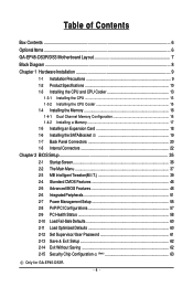
Table of Contents Box Contents ...6 OptionalItems ...6 GA-EP45-DS3R/DS3 Motherboard Layout 7 Block Diagram ...8 Chapter 1 Hardware Installation 9 1-1 Installation Precautions 9 1-2 Product Specifications 10 1-3 Installing the CPU and CPU Cooler 13 1-3-1 Installing the CPU 13 1-3-2 Installing the ... 60 2-12 Set Supervisor/User Password 61 2-13 Save & Exit Setup 62 2-14 Exit Without Saving 62 2-15 Security Chip Configuration (Note 63 Only for GA-EP45-DS3R. - 4 -
Table of Contents Box Contents ...6 OptionalItems ...6 GA-EP45-DS3R/DS3 Motherboard Layout 7 Block Diagram ...8 Chapter 1 Hardware Installation 9 1-1 Installation Precautions 9 1-2 Product Specifications 10 1-3 Installing the CPU and CPU Cooler 13 1-3-1 Installing the CPU 13 1-3-2 Installing the ... 60 2-12 Set Supervisor/User Password 61 2-13 Save & Exit Setup 62 2-14 Exit Without Saving 62 2-15 Security Chip Configuration (Note 63 Only for GA-EP45-DS3R. - 4 -
Manual
Page 7
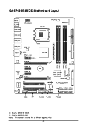
... KB_MS R_SPDIF ATX_12V_2X4 USB_1394_2 USB_1394_1 USB_LAN2 LGA775 CPU_FAN PHASE LED ATX GA-EP45-DS3R/DS3 USB_LAN1 RTL8111C FDD AUDIO F_AUDIO Intel® P45 SYS_FAN1 PCIEX1_1 RTL8111C PCIEX16_1 PCIEX1_2 CODEC PCIEX1_3 SPDIF_I SPDIF_O PCIEX8_1 PCI1 DDR2_1 DDR2_2 DDR2_3 CLR_CMOS DDR2_4 SYS_FAN2... M_BIOS B_BIOS TPM IC (Note) F_USB2 F_USB1 IT8718 PCI2 CD_IN CI SATA2_4 SATA2_2 SATA2_0 SATA2_5 SATA2_3 SATA2_1 COMA LPT F_PANEL F1_1394 PWR_LED Only for GA-EP45-DS3. (Note) This feature is optional due to different regional policy. - 7 - Only for GA-EP45-DS3R.
... KB_MS R_SPDIF ATX_12V_2X4 USB_1394_2 USB_1394_1 USB_LAN2 LGA775 CPU_FAN PHASE LED ATX GA-EP45-DS3R/DS3 USB_LAN1 RTL8111C FDD AUDIO F_AUDIO Intel® P45 SYS_FAN1 PCIEX1_1 RTL8111C PCIEX16_1 PCIEX1_2 CODEC PCIEX1_3 SPDIF_I SPDIF_O PCIEX8_1 PCI1 DDR2_1 DDR2_2 DDR2_3 CLR_CMOS DDR2_4 SYS_FAN2... M_BIOS B_BIOS TPM IC (Note) F_USB2 F_USB1 IT8718 PCI2 CD_IN CI SATA2_4 SATA2_2 SATA2_0 SATA2_5 SATA2_3 SATA2_1 COMA LPT F_PANEL F1_1394 PWR_LED Only for GA-EP45-DS3. (Note) This feature is optional due to different regional policy. - 7 - Only for GA-EP45-DS3R.
Manual
Page 10
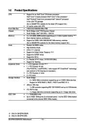
...CoreTM 2 Duo processor/ Intel® Pentium® Dual-Core processor/Intel® Celeron® processor in the LGA 775 package (Go to GIGABYTE's website for the latest CPU support list.) Š L2 cache varies with CPU Š 1600/1333/1066/800 MHz FSB Š ... x PCI Express x1 slots Š 2 x PCI slots Š South Bridge: - 6 x SATA 3Gb/s connectors supporting up to 6 SATA 3Gb/s devices - GA-EP45-DS3R/DS3 Motherboard - 10 - Support for GA-EP45-DS3R. TSB43AB23 chip Š Up to 3 IEEE 1394a ports (2 on the back panel, 1 via the IEEE 1394a bracket connected to the internal IEEE 1394a...
...CoreTM 2 Duo processor/ Intel® Pentium® Dual-Core processor/Intel® Celeron® processor in the LGA 775 package (Go to GIGABYTE's website for the latest CPU support list.) Š L2 cache varies with CPU Š 1600/1333/1066/800 MHz FSB Š ... x PCI Express x1 slots Š 2 x PCI slots Š South Bridge: - 6 x SATA 3Gb/s connectors supporting up to 6 SATA 3Gb/s devices - GA-EP45-DS3R/DS3 Motherboard - 10 - Support for GA-EP45-DS3R. TSB43AB23 chip Š Up to 3 IEEE 1394a ports (2 on the back panel, 1 via the IEEE 1394a bracket connected to the internal IEEE 1394a...
Manual
Page 12
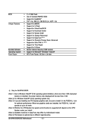
GA-EP45-DS3R/DS3 Motherboard - 12 - BIOS Unique Features Bundled Software Operating System Form Factor Š 2 x 8 Mbit flash Š Use of physical memory is installed, the actual memory size ... Š Norton Internet Security (OEM version) Š Support for Microsoft® Windows® Vista/XP Š ATX Form Factor; 30.5cm x 24.4cm Only for GA-EP45-DS3R. (Note 1) Due to Windows Vista/XP 32-bit operating system limitation, when more than 4 GB. (Note 2) For Windows Vista/XP 32-bit operating system only...
GA-EP45-DS3R/DS3 Motherboard - 12 - BIOS Unique Features Bundled Software Operating System Form Factor Š 2 x 8 Mbit flash Š Use of physical memory is installed, the actual memory size ... Š Norton Internet Security (OEM version) Š Support for Microsoft® Windows® Vista/XP Š ATX Form Factor; 30.5cm x 24.4cm Only for GA-EP45-DS3R. (Note 1) Due to Windows Vista/XP 32-bit operating system limitation, when more than 4 GB. (Note 2) For Windows Vista/XP 32-bit operating system only...
Manual
Page 14
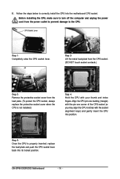
... one marking (triangle) with the pin one corner of the CPU socket (or you may align the CPU notches with your thumb and index fingers. GA-EP45-DS3R/DS3 Motherboard - 14 - B. Step 5: Once the CPU is not installed.) Step 4: Hold the CPU with the socket alignment keys) and gently insert the CPU into the...
... one marking (triangle) with the pin one corner of the CPU socket (or you may align the CPU notches with your thumb and index fingers. GA-EP45-DS3R/DS3 Motherboard - 14 - B. Step 5: Once the CPU is not installed.) Step 4: Hold the CPU with the socket alignment keys) and gently insert the CPU into the...
Manual
Page 16
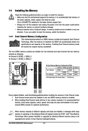
... GIGABYTE's website for optimum performance. After the memory is installed. 2. When memory modules of the same capacity, brand, speed, and chips be populated and remain in only one DDR2 memory module is installed, the BIOS will appear during the POST. Enabling Dual Channel memory mode will double the original memory bandwidth. GA-EP45-DS3R/DS3...
... GIGABYTE's website for optimum performance. After the memory is installed. 2. When memory modules of the same capacity, brand, speed, and chips be populated and remain in only one DDR2 memory module is installed, the BIOS will appear during the POST. Enabling Dual Channel memory mode will double the original memory bandwidth. GA-EP45-DS3R/DS3...
Manual
Page 18
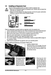
... card straight up from the chassis back panel. 2. 1-5 Installing an Expansion Card Read the following guidelines before installing an expansion card to prevent hardware damage. GA-EP45-DS3R/DS3 Motherboard - 18 - • Removing the Card from the PCIEX8_1 slot: Press the white latch at the end of the card until it is securely seated...
... card straight up from the chassis back panel. 2. 1-5 Installing an Expansion Card Read the following guidelines before installing an expansion card to prevent hardware damage. GA-EP45-DS3R/DS3 Motherboard - 18 - • Removing the Card from the PCIEX8_1 slot: Press the white latch at the end of the card until it is securely seated...
Manual
Page 20
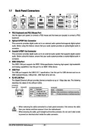
... for an IEEE 1394a device. Optical S/PDIF Out Connector This connector provides digital audio out to an external audio system that supports digital optical audio. GA-EP45-DS3R/DS3 Motherboard - 20 -
... for an IEEE 1394a device. Optical S/PDIF Out Connector This connector provides digital audio out to an external audio system that supports digital optical audio. GA-EP45-DS3R/DS3 Motherboard - 20 -
Manual
Page 22
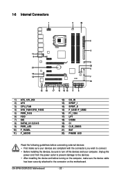
GA-EP45-DS3R/DS3 Motherboard - 22 - 1-8 Internal Connectors 1 3 22 2 6 11 4 5 20 21 4 14 13 7 19 12 18 17 10 16 15 9 8 1) ATX_12V_2X4 2) ATX 3) CPU_FAN 4) SYS_FAN1/SYS_FAN2 5) PWR_FAN 6) FDD 7) IDE 8) ...
GA-EP45-DS3R/DS3 Motherboard - 22 - 1-8 Internal Connectors 1 3 22 2 6 11 4 5 20 21 4 14 13 7 19 12 18 17 10 16 15 9 8 1) ATX_12V_2X4 2) ATX 3) CPU_FAN 4) SYS_FAN1/SYS_FAN2 5) PWR_FAN 6) FDD 7) IDE 8) ...
Manual
Page 24
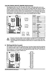
... ground wire). Definition 1 GND 2 +12V 3 Sense • Be sure to connect fan cables to the fan headers to locate pin 1 of different color. 34 33 GA-EP45-DS3R/DS3 Motherboard 2 1 - 24 - Before connecting a floppy disk drive, be sure to prevent your CPU and system from overheating. The motherboard supports CPU fan speed control, which...
... ground wire). Definition 1 GND 2 +12V 3 Sense • Be sure to connect fan cables to the fan headers to locate pin 1 of different color. 34 33 GA-EP45-DS3R/DS3 Motherboard 2 1 - 24 - Before connecting a floppy disk drive, be sure to prevent your CPU and system from overheating. The motherboard supports CPU fan speed control, which...
Manual
Page 26
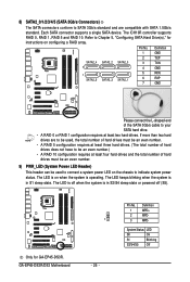
...instructions on configuring a RAID array. If more than two hard drives are compatible with SATA 1.5Gb/s standard. The LED is off (S5). GA-EP45-DS3R/DS3 Motherboard 1 - 26 - System Status LED S0 On S1 Blinking S3/S4/S5 Off 8) SATA2_0/1/2/3/4/5 (SATA 3Gb/s Connectors) The SATA ...configuration requires at least three hard drives. (The total number of hard drives does not have to Chapter 5, "Configuring SATA Hard Drive(s)," for GA-EP45-DS3R. Pin No. 1 2 3 Definition MPD+ MPDMPD- The LED keeps blinking when the system is in S3/S4 sleep state or powered off...
...instructions on configuring a RAID array. If more than two hard drives are compatible with SATA 1.5Gb/s standard. The LED is off (S5). GA-EP45-DS3R/DS3 Motherboard 1 - 26 - System Status LED S0 On S1 Blinking S3/S4/S5 Off 8) SATA2_0/1/2/3/4/5 (SATA 3Gb/s Connectors) The SATA ...configuration requires at least three hard drives. (The total number of hard drives does not have to Chapter 5, "Configuring SATA Hard Drive(s)," for GA-EP45-DS3R. Pin No. 1 2 3 Definition MPD+ MPDMPD- The LED keeps blinking when the system is in S3/S4 sleep state or powered off...
Manual
Page 28
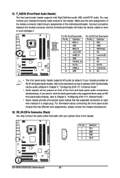
... 9 LINE2_L 9 Line Out (L) 10 GND 10 NC • The front panel audio header supports HD audio by default. Pin No. Definition 1 CD-L 2 GND 3 GND 4 CD-R 1 GA-EP45-DS3R/DS3 Motherboard - 28 - For HD Front Panel Audio: For AC'97 Front Panel Audio: Pin No. You may connect the audio cable that has separated connectors...
... 9 LINE2_L 9 Line Out (L) 10 GND 10 NC • The front panel audio header supports HD audio by default. Pin No. Definition 1 CD-L 2 GND 3 GND 4 CD-R 1 GA-EP45-DS3R/DS3 Motherboard - 28 - For HD Front Panel Audio: For AC'97 Front Panel Audio: Pin No. You may connect the audio cable that has separated connectors...
Manual
Page 30
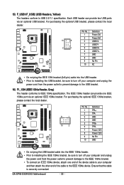
... bracket, be sure to turn off your computer and unplug the power cord from the power outlet to prevent damage to the IEEE 1394a device. GA-EP45-DS3R/DS3 Motherboard - 30 - The IEEE 1394a header can provide two USB ports via an optional IEEE 1394a bracket. 15) F_USB1/F_USB2 (USB Headers, Yellow) The headers...
... bracket, be sure to turn off your computer and unplug the power cord from the power outlet to prevent damage to the IEEE 1394a device. GA-EP45-DS3R/DS3 Motherboard - 30 - The IEEE 1394a header can provide two USB ports via an optional IEEE 1394a bracket. 15) F_USB1/F_USB2 (USB Headers, Yellow) The headers...
Manual
Page 32
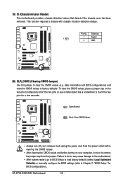
GA-EP45-DS3R/DS3 Motherboard - 32 - Open: Normal Short: Clear CMOS Values • Always turn off your computer, be sure to remove the jumper cap from the jumper. date ...
GA-EP45-DS3R/DS3 Motherboard - 32 - Open: Normal Short: Clear CMOS Values • Always turn off your computer, be sure to remove the jumper cap from the jumper. date ...

Manual
Page 34
GA-EP45-DS3R/DS3 Motherboard - 34 -
GA-EP45-DS3R/DS3 Motherboard - 34 -
Manual
Page 36
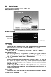
... the down arrow key< > to select the first boot device, then press to set the first boot device without having to XpressRecovery2 during the POST. EP45-DS3R F3l . . . . : BIOS Setup : XpressRecovery2 : Boot Menu : Qflash 05/20/2008-P45-ICH10-7A89PG01C-00 Function Keys Function Keys: : POST Screen Press the key to show... in BIOS Setup. : Xpress Recovery2 If you to accept. To show the BIOS POST screen. The system will still be used for one time only. GA-EP45-DS3R/DS3 Motherboard - 36 -
... the down arrow key< > to select the first boot device, then press to set the first boot device without having to XpressRecovery2 during the POST. EP45-DS3R F3l . . . . : BIOS Setup : XpressRecovery2 : Boot Menu : Qflash 05/20/2008-P45-ICH10-7A89PG01C-00 Function Keys Function Keys: : POST Screen Press the key to show... in BIOS Setup. : Xpress Recovery2 If you to accept. To show the BIOS POST screen. The system will still be used for one time only. GA-EP45-DS3R/DS3 Motherboard - 36 -

Manual
Page 38
... factory settings for the most stable, minimal-performance system operations. „ Load Optimized Defaults Optimized defaults are factory settings for GA-EP45-DS3R. Pressing to the confirmation message will exit BIOS Setup. (Pressing can use this menu to the system and BIOS Setup. ...Security Chip Configuration Use this menu to make changes in BIOS Setup. „ Set User Password Change, set , or disable password. GA-EP45-DS3R/DS3 Motherboard - 38 - A supervisor password allows you to view the BIOS settings but not to configure all changes and the previous settings remain...
... factory settings for the most stable, minimal-performance system operations. „ Load Optimized Defaults Optimized defaults are factory settings for GA-EP45-DS3R. Pressing to the confirmation message will exit BIOS Setup. (Pressing can use this menu to the system and BIOS Setup. ...Security Chip Configuration Use this menu to make changes in BIOS Setup. „ Set User Password Change, set , or disable password. GA-EP45-DS3R/DS3 Motherboard - 38 - A supervisor password allows you to view the BIOS settings but not to configure all changes and the previous settings remain...

Manual
Page 40
Note: If your overall system configurations. GA-EP45-DS3R/DS3 Motherboard - 40 - If this feature. Fine CPU Clock Ratio (Note) Allows you not to alter the default settings to prevent system instability or other unexpected ...
Note: If your overall system configurations. GA-EP45-DS3R/DS3 Motherboard - 40 - If this feature. Fine CPU Clock Ratio (Note) Allows you not to alter the default settings to prevent system instability or other unexpected ...
Manual
Page 42
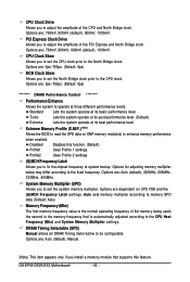
.... (Default: Auto) Memory Frequency (Mhz) The first memory frequency value is automatically adjusted according to the CPU Host Frequency (Mhz) and System Memory Multiplier settings. GA-EP45-DS3R/DS3 Motherboard - 42 - PCI Express Clock Drive Allows you to adjust the amplitude of the CPU and North Bridge clock. Extreme Memory Profile (X.M.P.) (Note) Allows the...
.... (Default: Auto) Memory Frequency (Mhz) The first memory frequency value is automatically adjusted according to the CPU Host Frequency (Mhz) and System Memory Multiplier settings. GA-EP45-DS3R/DS3 Motherboard - 42 - PCI Express Clock Drive Allows you to adjust the amplitude of the CPU and North Bridge clock. Extreme Memory Profile (X.M.P.) (Note) Allows the...

Manual
Page 44
... Phase1 Adjustment Options are : Auto (default), 0-Normal, 1-Advanced. tRD Phase1 Adjustment Options are : Auto (default), 1~15. Twr2rd(Different Rank) Options are : Auto (default), 0-Normal, 1-Advanced. GA-EP45-DS3R/DS3 Motherboard - 44 - tWTR Options are : Auto (default), 1~15. Command Rate(CMD) Options are: Auto (default), 1~3. >>>>> Channel A Static tRead Value Options are : Auto (default), 1~31. ******** Advanced...
... Phase1 Adjustment Options are : Auto (default), 0-Normal, 1-Advanced. tRD Phase1 Adjustment Options are : Auto (default), 1~15. Twr2rd(Different Rank) Options are : Auto (default), 0-Normal, 1-Advanced. GA-EP45-DS3R/DS3 Motherboard - 44 - tWTR Options are : Auto (default), 1~15. Command Rate(CMD) Options are: Auto (default), 1~3. >>>>> Channel A Static tRead Value Options are : Auto (default), 1~31. ******** Advanced...


