Manual
Page 3
... is protected by GIGA-BYTE TECHNOLOGY CO., LTD as the exclu- For example, "REV: 1.0" means the revision of GIGABYTE branded motherboards. Example: sive global distributor of the motherboard is the property of the product, read the Quick Installation Guide included...Guide page on your motherboard revision before updating motherboard BIOS, drivers, or when looking for technical information. by GIGABYTE without GIGABYTE's prior written permission. GIGABYTE UNITED INC. Changes to the specifications and features in the use GIGABYTE's unique features, read the User's Manual. ...
... is protected by GIGA-BYTE TECHNOLOGY CO., LTD as the exclu- For example, "REV: 1.0" means the revision of GIGABYTE branded motherboards. Example: sive global distributor of the motherboard is the property of the product, read the Quick Installation Guide included...Guide page on your motherboard revision before updating motherboard BIOS, drivers, or when looking for technical information. by GIGABYTE without GIGABYTE's prior written permission. GIGABYTE UNITED INC. Changes to the specifications and features in the use GIGABYTE's unique features, read the User's Manual. ...
Manual
Page 4
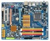
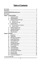
Table of Contents Box Contents ...6 OptionalItems ...6 GA-EP45-DS3R/DS3 Motherboard Layout 7 Block Diagram ...8 Chapter 1 Hardware Installation 9 1-1 Installation Precautions 9 1-2 Product Specifications 10 1-3 Installing the CPU and CPU Cooler ... the SATA Bracket 19 1-7 Back Panel Connectors 20 1-8 Internal Connectors 22 Chapter 2 BIOS Setup 35 2-1 Startup Screen 36 2-2 The Main Menu 37 2-3 MB Intelligent Tweaker(M.I.T 39 2-4 Standard CMOS Features 46 2-5 Advanced BIOS Features 48 2-6 IntegratedPeripherals 51 2-7 Power Management Setup 55 2-8 PnP/PCI Configurations 57 ...
Table of Contents Box Contents ...6 OptionalItems ...6 GA-EP45-DS3R/DS3 Motherboard Layout 7 Block Diagram ...8 Chapter 1 Hardware Installation 9 1-1 Installation Precautions 9 1-2 Product Specifications 10 1-3 Installing the CPU and CPU Cooler ... the SATA Bracket 19 1-7 Back Panel Connectors 20 1-8 Internal Connectors 22 Chapter 2 BIOS Setup 35 2-1 Startup Screen 36 2-2 The Main Menu 37 2-3 MB Intelligent Tweaker(M.I.T 39 2-4 Standard CMOS Features 46 2-5 Advanced BIOS Features 48 2-6 IntegratedPeripherals 51 2-7 Power Management Setup 55 2-8 PnP/PCI Configurations 57 ...
Manual
Page 5
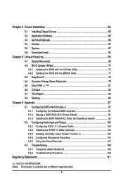
...66 3-4 Contact ...67 3-5 System ...67 3-6 Download Center 68 Chapter 4 Unique Features 69 4-1 Xpress Recovery2 69 4-2 BIOS Update Utilities 74 4-2-1 Updating the BIOS with the Q-Flash Utility 74 4-2-2 Updating the BIOS with the @BIOS Utility 77 4-3 EasyTune 6 ...78 4-4 Dynamic Energy Saver Advanced 79 4-5 Ultra TPM (Note 81 4-6 Q-Share ...82... the Sound Recorder 107 5-3 Troubleshooting 108 5-3-1 Frequently Asked Questions 108 5-3-2 Troubleshooting Procedure 109 Regulatory Statements 111 Only for GA-EP45-DS3R. (Note) This feature is optional due to different regional policy. - 5 -
...66 3-4 Contact ...67 3-5 System ...67 3-6 Download Center 68 Chapter 4 Unique Features 69 4-1 Xpress Recovery2 69 4-2 BIOS Update Utilities 74 4-2-1 Updating the BIOS with the Q-Flash Utility 74 4-2-2 Updating the BIOS with the @BIOS Utility 77 4-3 EasyTune 6 ...78 4-4 Dynamic Energy Saver Advanced 79 4-5 Ultra TPM (Note 81 4-6 Q-Share ...82... the Sound Recorder 107 5-3 Troubleshooting 108 5-3-1 Frequently Asked Questions 108 5-3-2 Troubleshooting Procedure 109 Regulatory Statements 111 Only for GA-EP45-DS3R. (Note) This feature is optional due to different regional policy. - 5 -
Manual
Page 8
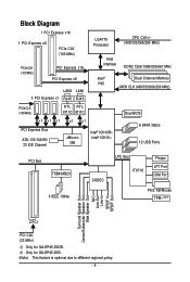
Only for GA-EP45-DS3R. Block Diagram 1 PCI Express x16 1 PCI Express x8 PCIe CLK (100 MHz) PCIe CLK (100 MHz) PCI Express x16 PCI Express x8 ...667 MHz Intel® P45 Dual Channel Memory MCH CLK (400/333/266/200 MHz) PCIe CLK (100 MHz) RTL RTL 8111C 8111C Dual BIOS x1 x1 x1 PCI Express Bus ATA-133/100/66/ 33 IDE Channel x1 x1 JMicron 368 Intel® ICH10R Intel® ICH10 6 .../Subwoofer Speaker Out Side Speaker Out MIC Line-Out Line-In SPDIF In SPDIF Out 2 PCI PCI CLK (33 MHz) Only for GA-EP45-DS3. (Note) This feature is optional due to different regional policy. - 8 -
Only for GA-EP45-DS3R. Block Diagram 1 PCI Express x16 1 PCI Express x8 PCIe CLK (100 MHz) PCIe CLK (100 MHz) PCI Express x16 PCI Express x8 ...667 MHz Intel® P45 Dual Channel Memory MCH CLK (400/333/266/200 MHz) PCIe CLK (100 MHz) RTL RTL 8111C 8111C Dual BIOS x1 x1 x1 PCI Express Bus ATA-133/100/66/ 33 IDE Channel x1 x1 JMicron 368 Intel® ICH10R Intel® ICH10 6 .../Subwoofer Speaker Out Side Speaker Out MIC Line-Out Line-In SPDIF In SPDIF Out 2 PCI PCI CLK (33 MHz) Only for GA-EP45-DS3. (Note) This feature is optional due to different regional policy. - 8 -
Manual
Page 12
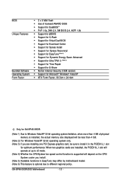
GA-EP45-DS3R/DS3 Motherboard - 12 - When two graphics cards are installed, the PCIEX16_1 slot will operate ... you are installing one PCI Express graphics card, be sure to different regional policy. BIOS Unique Features Bundled Software Operating System Form Factor Š 2 x 8 Mbit flash Š Use of licensed AWARD... BIOS Š Support for DualBIOSTM Š PnP 1.0a, DMI 2.0, SM BIOS 2.4, ACPI 1.0b Š Support for @BIOS Š Support for Q-Flash Š Support for Virtual Dual BIOS Š Support for Download Center Š Support for Xpress...
GA-EP45-DS3R/DS3 Motherboard - 12 - When two graphics cards are installed, the PCIEX16_1 slot will operate ... you are installing one PCI Express graphics card, be sure to different regional policy. BIOS Unique Features Bundled Software Operating System Form Factor Š 2 x 8 Mbit flash Š Use of licensed AWARD... BIOS Š Support for DualBIOSTM Š PnP 1.0a, DMI 2.0, SM BIOS 2.4, ACPI 1.0b Š Support for @BIOS Š Support for Q-Flash Š Support for Virtual Dual BIOS Š Support for Download Center Š Support for Xpress...
Manual
Page 16
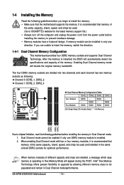
... will automatically detect the specifications and capacity of the same capacity, brand, speed, and chips be used . (Go to GIGABYTE's website for optimum performance. DS/SS Four Modules DS/SS DS/SS DS/SS DS/SS (SS=Single-Sided, DS...Channel mode. 1. Dual Channel mode cannot be installed in only one DDR2 memory module is installed, the BIOS will double the original memory bandwidth. The four DDR2 memory sockets are divided into two channels and each ... provides four DDR2 memory sockets and supports Dual Channel Technology. DS/SS - - GA-EP45-DS3R/DS3 Motherboard - 16 -
... will automatically detect the specifications and capacity of the same capacity, brand, speed, and chips be used . (Go to GIGABYTE's website for optimum performance. DS/SS Four Modules DS/SS DS/SS DS/SS DS/SS (SS=Single-Sided, DS...Channel mode. 1. Dual Channel mode cannot be installed in only one DDR2 memory module is installed, the BIOS will double the original memory bandwidth. The four DDR2 memory sockets are divided into two channels and each ... provides four DDR2 memory sockets and supports Dual Channel Technology. DS/SS - - GA-EP45-DS3R/DS3 Motherboard - 16 -
Manual
Page 18
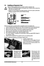
...installing an expansion card to prevent hardware damage. Carefully read the manual that supports your computer. Secure the card's metal bracket to make any required BIOS changes for your expansion card in your expansion card. • Always turn off the computer and unplug the power cord from the slot. Install... in the slot and does not rock. • Removing the Card from the PCIEX16_1 slot: Gently push back on the lever on your card. GA-EP45-DS3R/DS3 Motherboard - 18 - • Removing the Card from the PCIEX8_1 slot: Press the white latch at the end of the card until it is ...
...installing an expansion card to prevent hardware damage. Carefully read the manual that supports your computer. Secure the card's metal bracket to make any required BIOS changes for your expansion card in your expansion card. • Always turn off the computer and unplug the power cord from the slot. Install... in the slot and does not rock. • Removing the Card from the PCIEX16_1 slot: Gently push back on the lever on your card. GA-EP45-DS3R/DS3 Motherboard - 18 - • Removing the Card from the PCIEX8_1 slot: Press the white latch at the end of the card until it is ...
Manual
Page 27
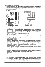
...The front panel design may differ by issuing a beep code. Hardware Installation When connecting your system using the power switch (refer to Chapter 2, "BIOS Setup," "Power Management Setup," for information about beep codes. • HD (Hard Drive Activity LED, Blue) Connects to the hard drive activity... problem. PW+ PWSPEAK+ SPEAK- 2 20 1 19 HD+ HD- The LED keeps blinking when S1 Blinking the system is detected, the BIOS may configure the way to turn off when the system is operating. The system reports system startup status by chassis. 10) F_PANEL (Front Panel...
...The front panel design may differ by issuing a beep code. Hardware Installation When connecting your system using the power switch (refer to Chapter 2, "BIOS Setup," "Power Management Setup," for information about beep codes. • HD (Hard Drive Activity LED, Blue) Connects to the hard drive activity... problem. PW+ PWSPEAK+ SPEAK- 2 20 1 19 HD+ HD- The LED keeps blinking when S1 Blinking the system is detected, the BIOS may configure the way to turn off when the system is operating. The system reports system startup status by chassis. 10) F_PANEL (Front Panel...
Manual
Page 32
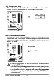
... Load Optimized Defaults) or manually configure the BIOS settings (refer to touch the two pins for BIOS configurations). To clear the CMOS values, place a jumper cap on your computer and unplug the power cord from the jumper. GA-EP45-DS3R/DS3 Motherboard - 32 - Pin No. date information and BIOS configurations) and reset the CMOS values to...
... Load Optimized Defaults) or manually configure the BIOS settings (refer to touch the two pins for BIOS configurations). To clear the CMOS values, place a jumper cap on your computer and unplug the power cord from the jumper. GA-EP45-DS3R/DS3 Motherboard - 32 - Pin No. date information and BIOS configurations) and reset the CMOS values to...
Manual
Page 33
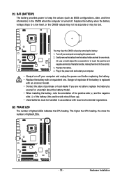
... turned off your computer and unplug the power cord. 2. Replace the battery. 4. 21) BAT (BATTERY) The battery provides power to keep the values (such as BIOS configurations, date, and time information) in the CMOS when the computer is replaced with an incorrect model. • Contact the place of purchase or local...
... turned off your computer and unplug the power cord. 2. Replace the battery. 4. 21) BAT (BATTERY) The battery provides power to keep the values (such as BIOS configurations, date, and time information) in the CMOS when the computer is replaced with an incorrect model. • Contact the place of purchase or local...
Manual
Page 35
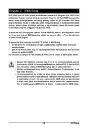
... is recommended that you not alter the default settings (unless you need to) to boot. To upgrade the BIOS, use either the GIGABYTE Q-Flash or @BIOS utility. • Q-Flash allows the user to clear the CMOS values.) - 35 - BIOS Setup Refer to Chapter 5, "Troubleshooting," for how to quickly and easily upgrade or back up...
... is recommended that you not alter the default settings (unless you need to) to boot. To upgrade the BIOS, use either the GIGABYTE Q-Flash or @BIOS utility. • Q-Flash allows the user to clear the CMOS values.) - 35 - BIOS Setup Refer to Chapter 5, "Troubleshooting," for how to quickly and easily upgrade or back up...
Manual
Page 36
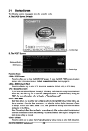
... one time only. You can be based on page 50. : BIOS Setup/Q-Flash Press the key to enter BIOS Setup or to access the Q-Flash utility in BIOS Setup. : Xpress Recovery2 If you to set the first boot device without having to accept. GA-EP45-DS3R/DS3 Motherboard - 36 - To exit Boot Menu, press . For more...
... one time only. You can be based on page 50. : BIOS Setup/Q-Flash Press the key to enter BIOS Setup or to access the Q-Flash utility in BIOS Setup. : Xpress Recovery2 If you to set the first boot device without having to accept. GA-EP45-DS3R/DS3 Motherboard - 36 - To exit Boot Menu, press . For more...

Manual
Page 37
... arrow keys to move among the items and press to accept or enter a sub-menu. (Sample BIOS Version: GA-EP45-DS3R F3l) CMOS Setup Utility-Copyright (C) 1984-2008 Award Software ` MB Intelligent Tweaker(M.I.T.) ` Standard CMOS Features ` Advanced BIOS Features ` Integrated Peripherals ` Power Management Setup ` PnP/PCI Configurations ` PC Health Status Load Fail-Safe Defaults...
... arrow keys to move among the items and press to accept or enter a sub-menu. (Sample BIOS Version: GA-EP45-DS3R F3l) CMOS Setup Utility-Copyright (C) 1984-2008 Award Software ` MB Intelligent Tweaker(M.I.T.) ` Standard CMOS Features ` Advanced BIOS Features ` Integrated Peripherals ` Power Management Setup ` PnP/PCI Configurations ` PC Health Status Load Fail-Safe Defaults...

Manual
Page 38
... the TPM function. An user password only allows you to 8 profiles (Profile 1-8) and name each profile. A supervisor password allows you to view the BIOS settings but not to make changes in effect. You can also carry out this menu to a profile. „ The Functions of reconfiguring the BIOS settings. GA-EP45-DS3R/DS3 Motherboard - 38 -
... the TPM function. An user password only allows you to 8 profiles (Profile 1-8) and name each profile. A supervisor password allows you to view the BIOS settings but not to make changes in effect. You can also carry out this menu to a profile. „ The Functions of reconfiguring the BIOS settings. GA-EP45-DS3R/DS3 Motherboard - 38 -
Manual
Page 39
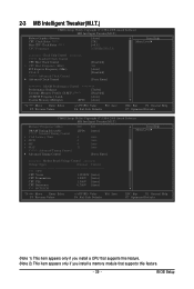
... appears only if you install a CPU that supports this feature. (Note 2) This item appears only if you install a memory module that supports this feature. - 39 - BIOS Setup
... appears only if you install a CPU that supports this feature. (Note 2) This item appears only if you install a memory module that supports this feature. - 39 - BIOS Setup

Manual
Page 40
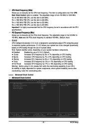
... item below to automatically set in system's failure to CPU, chipset, or memory and reduce the useful life of CPU host clock. Auto allows the BIOS to be configurable. Note: If your overall system configurations. This page is installed. CPU Frequency Displays the current operating CPU frequency. ******** Clock Chip Control Standard... to increase the CPU clock ratio set the R.G.B. Fine CPU Clock Ratio (Note) Allows you to enhance the performance of the graphics chip and memory. GA-EP45-DS3R/DS3 Motherboard - 40 - If this feature.
... item below to automatically set in system's failure to CPU, chipset, or memory and reduce the useful life of CPU host clock. Auto allows the BIOS to be configurable. Note: If your overall system configurations. This page is installed. CPU Frequency Displays the current operating CPU frequency. ******** Clock Chip Control Standard... to increase the CPU clock ratio set the R.G.B. Fine CPU Clock Ratio (Note) Allows you to enhance the performance of the graphics chip and memory. GA-EP45-DS3R/DS3 Motherboard - 40 - If this feature.
Manual
Page 41
... sets the PCIe clock frequency to standard 100 MHz. (Default: Auto) C.I.A.2 CPU Intelligent Accelerator 2 (C.I.A.2) is from 90 MHz to manually set the PCIe clock frequency. BIOS Setup For a 1066 MHz FSB CPU, set this item to be set this item to maximize system performance. For a 1333 MHz FSB CPU, set in...
... sets the PCIe clock frequency to standard 100 MHz. (Default: Auto) C.I.A.2 CPU Intelligent Accelerator 2 (C.I.A.2) is from 90 MHz to manually set the PCIe clock frequency. BIOS Setup For a 1066 MHz FSB CPU, set this item to be set this item to maximize system performance. For a 1333 MHz FSB CPU, set in...
Manual
Page 42
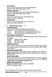
...system operate at its good performance level. (Default) Lets the system operate at three different performance levels. Disabled Profile1 Disables this feature. GA-EP45-DS3R/DS3 Motherboard - 42 - CPU Clock Drive Allows you to adjust the amplitude of the PCI Express and North Bridge clock. Options are :... 700mV, 800mV, 900mV (default), 1000mV. Extreme Memory Profile (X.M.P.) (Note) Allows the BIOS to read the SPD data on CPU FSB and the (G)...
...system operate at its good performance level. (Default) Lets the system operate at three different performance levels. Disabled Profile1 Disables this feature. GA-EP45-DS3R/DS3 Motherboard - 42 - CPU Clock Drive Allows you to adjust the amplitude of the PCI Express and North Bridge clock. Options are :... 700mV, 800mV, 900mV (default), 1000mV. Extreme Memory Profile (X.M.P.) (Note) Allows the BIOS to read the SPD data on CPU FSB and the (G)...

Manual
Page 43
...` KLJI: Move Enter: Select F5: Previous Values +/-/PU/PD: Value F10: Save F6: Fail-Safe Defaults ESC: Exit F1: General Help F7: Optimized Defaults - 43 - BIOS Setup >>>>> Standard Timing Control CAS Latency Time Options are : Auto (default), 1~15. tRP Options are : Auto (default), 3~7.
...` KLJI: Move Enter: Select F5: Previous Values +/-/PU/PD: Value F10: Save F6: Fail-Safe Defaults ESC: Exit F1: General Help F7: Optimized Defaults - 43 - BIOS Setup >>>>> Standard Timing Control CAS Latency Time Options are : Auto (default), 1~15. tRP Options are : Auto (default), 3~7.
Manual
Page 45
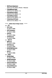
... MCH Core The default is Auto. MCH/DRAM Reference The default is Auto. ICH I/O The default is Auto. >>> DRAM DRAM Voltage The default is Auto. BIOS Setup Twr2wr(Different Rank) Options are : Auto (default), 1~15. Channel A Reference The default is Auto. Twr2rd(Different Rank) Options are : Auto (default), 0-Normal, 1-Advanced. DRAM...
... MCH Core The default is Auto. MCH/DRAM Reference The default is Auto. ICH I/O The default is Auto. >>> DRAM DRAM Voltage The default is Auto. BIOS Setup Twr2wr(Different Rank) Options are : Auto (default), 1~15. Channel A Reference The default is Auto. Twr2rd(Different Rank) Options are : Auto (default), 0-Normal, 1-Advanced. DRAM...


