Manual
Page 1
GA-EP43T-S3L LGA775 socket motherboard for Intel® Core™ processor family/ Intel® Pentium® processor family/Intel® Celeron® processor family User's Manual Rev. 1001 12ME-EP43T3L-1001R
GA-EP43T-S3L LGA775 socket motherboard for Intel® Core™ processor family/ Intel® Pentium® processor family/Intel® Celeron® processor family User's Manual Rev. 1001 12ME-EP43T3L-1001R
Manual
Page 2
Motherboard GA-EP43T-S3L Apr. 30, 2009 Motherboard GA-EP43T-S3L Apr. 30, 2009
Motherboard GA-EP43T-S3L Apr. 30, 2009 Motherboard GA-EP43T-S3L Apr. 30, 2009
Manual
Page 3
...any form or by any means without prior notice. For product-related information, check on our website at: http://www.gigabyte.com.tw Identifying Your Motherboard Revision The revision number on our website. Disclaimer Information in this manual may be reproduced, ...'s Manual. No part of this manual is protected by GIGABYTE without GIGABYTE's prior written permission. Check your motherboard looks like this product, GIGABYTE provides the following types of documentations: For quick set-up of GIGABYTE. Changes to their respective owners. Copyright © 2009 GIGA...
...any form or by any means without prior notice. For product-related information, check on our website at: http://www.gigabyte.com.tw Identifying Your Motherboard Revision The revision number on our website. Disclaimer Information in this manual may be reproduced, ...'s Manual. No part of this manual is protected by GIGABYTE without GIGABYTE's prior written permission. Check your motherboard looks like this product, GIGABYTE provides the following types of documentations: For quick set-up of GIGABYTE. Changes to their respective owners. Copyright © 2009 GIGA...
Manual
Page 4
Table of Contents Box Contents...6 Optional Items...6 GA-EP43T-S3L Motherboard Layout 7 Block Diagram...8 Chapter 1 Hardware Installation 9 1-1 Installation Precautions 9 1-2 Product Specifications 10 1-3 Installing the CPU and CPU Cooler 13 1-3-1 Installing the CPU 13 1-3-2 Installing the ...
Table of Contents Box Contents...6 Optional Items...6 GA-EP43T-S3L Motherboard Layout 7 Block Diagram...8 Chapter 1 Hardware Installation 9 1-1 Installation Precautions 9 1-2 Product Specifications 10 1-3 Installing the CPU and CPU Cooler 13 1-3-1 Installing the CPU 13 1-3-2 Installing the ...
Manual
Page 5
Chapter 3 Drivers Installation 61 3-1 Installing Chipset Drivers 61 3-2 Application Software 62 3-3 Technical Manuals 62 3-4 Contact...63 3-5 System...63 3-6 Download Center 64 Chapter 4 Unique Features 65 4-1 Xpress Recovery2 65 4-2 BIOS Update Utilities 68 4-2-1 Updating the BIOS with the Q-Flash Utility 68 4-2-2 Updating the BIOS with the @BIOS Utility 71 4-3 EasyTune 6...72 4-4 Dynamic Energy Saver Advanced 73 4-5 Q-Share...75 4-6 Time Repair...76 Chapter 5 Appendix...77 5-1 Configuring Audio Input and Output 77 5-1-1 Configuring 2/4/5.1/7.1-Channel Audio 77 5-1-2 Configuring ...
Chapter 3 Drivers Installation 61 3-1 Installing Chipset Drivers 61 3-2 Application Software 62 3-3 Technical Manuals 62 3-4 Contact...63 3-5 System...63 3-6 Download Center 64 Chapter 4 Unique Features 65 4-1 Xpress Recovery2 65 4-2 BIOS Update Utilities 68 4-2-1 Updating the BIOS with the Q-Flash Utility 68 4-2-2 Updating the BIOS with the @BIOS Utility 71 4-3 EasyTune 6...72 4-4 Dynamic Energy Saver Advanced 73 4-5 Q-Share...75 4-6 Time Repair...76 Chapter 5 Appendix...77 5-1 Configuring Audio Input and Output 77 5-1-1 Configuring 2/4/5.1/7.1-Channel Audio 77 5-1-2 Configuring ...
Manual
Page 6
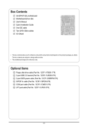
Box Contents GA-EP43T-S3L motherboard Motherboard driver disk User's Manual Quick Installation Guide One IDE cable Two SATA 3Gb/s cables I/O Shield • The box contents above are subject to ...
Box Contents GA-EP43T-S3L motherboard Motherboard driver disk User's Manual Quick Installation Guide One IDE cable Two SATA 3Gb/s cables I/O Shield • The box contents above are subject to ...
Manual
Page 7
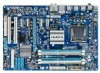
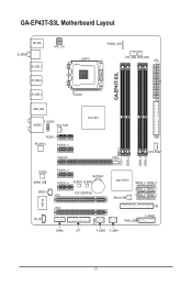
GA-EP43T-S3L Motherboard Layout KB_MS R_SPDIF R_USB_1 ATX_12V LGA775 PHASE_LED CPU_FAN PWR_FAN ATX GA-EP43T-S3L R_USB_2 R_USB_3 USB_LAN F_AUDIO AUDIO SYS_FAN1 PCIEX1_1 RTL8111C PCIEX1_2 PCIEX16 Intel® P43 FDD SYS_FAN2 DDR3_1 DDR3_2 DDR3_3 DDR3_4 CODEC SPDIF_O SPDIF_I CD_IN IT8718 PCIEX1_3 PCIEX1_4 BATTERY M_BIOS B_BIOS CLR_CMOS PCI1 Intel® ICH10 JMicron 368 SATA2_3 SATA2_0 SATA2_4 SATA2_1 SATA2_5 SATA2_2 PCI2 IDE F_PANEL PWR_LED CI COMA LPT F_USB2 F_USB1 - 7 -
GA-EP43T-S3L Motherboard Layout KB_MS R_SPDIF R_USB_1 ATX_12V LGA775 PHASE_LED CPU_FAN PWR_FAN ATX GA-EP43T-S3L R_USB_2 R_USB_3 USB_LAN F_AUDIO AUDIO SYS_FAN1 PCIEX1_1 RTL8111C PCIEX1_2 PCIEX16 Intel® P43 FDD SYS_FAN2 DDR3_1 DDR3_2 DDR3_3 DDR3_4 CODEC SPDIF_O SPDIF_I CD_IN IT8718 PCIEX1_3 PCIEX1_4 BATTERY M_BIOS B_BIOS CLR_CMOS PCI1 Intel® ICH10 JMicron 368 SATA2_3 SATA2_0 SATA2_4 SATA2_1 SATA2_5 SATA2_2 PCI2 IDE F_PANEL PWR_LED CI COMA LPT F_USB2 F_USB1 - 7 -
Manual
Page 8
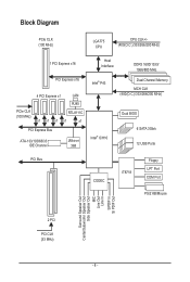
Block Diagram PCIe CLK (100 MHz) LGA775 CPU CPU CLK+/(400(O.C.)/333/266/200 MHz) 1 PCI Express x16 PCI Express x16 PCIe CLK (100 MHz) 4 PCI Express x1 LAN RJ45 RTL8111C x1 x1 x1 x1 x1 PCI Express Bus ATA-133/100/66/33 IDE Channel JMicron 368 Host Interface DDR3 1600/1333/ 1066/800 MHz Intel® P43 Dual Channel Memory MCH CLK (400(O.C.)/333/266/200 MHz) Intel® ICH10 Dual BIOS 6 SATA 3Gb/s 12 USB Ports PCI Bus CODEC IT8718 Floppy LPT Port COM Port PS/2 KB/Mouse Surround Speaker Out Center/Subwoofer Speaker Out Side Speaker Out MIC Line Out Line In S/PDIF In S/ ...
Block Diagram PCIe CLK (100 MHz) LGA775 CPU CPU CLK+/(400(O.C.)/333/266/200 MHz) 1 PCI Express x16 PCI Express x16 PCIe CLK (100 MHz) 4 PCI Express x1 LAN RJ45 RTL8111C x1 x1 x1 x1 x1 PCI Express Bus ATA-133/100/66/33 IDE Channel JMicron 368 Host Interface DDR3 1600/1333/ 1066/800 MHz Intel® P43 Dual Channel Memory MCH CLK (400(O.C.)/333/266/200 MHz) Intel® ICH10 Dual BIOS 6 SATA 3Gb/s 12 USB Ports PCI Bus CODEC IT8718 Floppy LPT Port COM Port PS/2 KB/Mouse Surround Speaker Out Center/Subwoofer Speaker Out Side Speaker Out MIC Line Out Line In S/PDIF In S/ ...
Manual
Page 9
Prior to installation, carefully read the user's manual and follow these procedures: • Prior to installation, do not have an ESD wrist strap, keep your hands dry and first touch a metal object to eliminate static electricity. • Prior to installing the motherboard, please have a problem related to wear an electrostatic discharge (ESD) wrist strap when handling electronic com- ponents such as a motherboard, CPU or memory. These stickers are required for warranty validation. • Always remove the AC power by your hardware components are connected. • To prevent ...
Prior to installation, carefully read the user's manual and follow these procedures: • Prior to installation, do not have an ESD wrist strap, keep your hands dry and first touch a metal object to eliminate static electricity. • Prior to installing the motherboard, please have a problem related to wear an electrostatic discharge (ESD) wrist strap when handling electronic com- ponents such as a motherboard, CPU or memory. These stickers are required for warranty validation. • Always remove the AC power by your hardware components are connected. • To prevent ...
Manual
Page 10
.../Intel® Core™ 2 Duo processor/ Intel® Pentium® processor/Intel® Celeron® processor in the LGA775 package (Go to GIGABYTE's website for the latest CPU support list.) L2 cache varies with CPU 1600(O.C.)/1333/1066/800 MHz FSB North Bridge: Intel® P43 Express Chipset...up to 8 GB of system memory (Note 1) Dual channel memory architecture Support for DDR3 1600/1333/1066/800 MHz memory modules (Go to GIGABYTE's website for the latest memory support list.) Realtek ALC888 codec High Definition Audio 2/4/5.1/7.1-channel Support for S/PDIF In/Out Support for CD In ...
.../Intel® Core™ 2 Duo processor/ Intel® Pentium® processor/Intel® Celeron® processor in the LGA775 package (Go to GIGABYTE's website for the latest CPU support list.) L2 cache varies with CPU 1600(O.C.)/1333/1066/800 MHz FSB North Bridge: Intel® P43 Express Chipset...up to 8 GB of system memory (Note 1) Dual channel memory architecture Support for DDR3 1600/1333/1066/800 MHz memory modules (Go to GIGABYTE's website for the latest memory support list.) Realtek ALC888 codec High Definition Audio 2/4/5.1/7.1-channel Support for S/PDIF In/Out Support for CD In ...
Manual
Page 11
Hardware Installation Internal Connectors w w w w w w w w w w w w w w w w w w w Back Panel w Connectors w w w w w w I/O Controller w Hardware Monitor w w w w w w 1 x 24-pin ATX main power connector 1 x 4-pin ATX 12V power connector 1 x floppy disk drive connector 1 x IDE connector 6 x SATA 3Gb/s connectors 1 x CPU fan header 2 x system fan headers 1 x power fan header 1 x front panel header 1 x front panel audio ...
Hardware Installation Internal Connectors w w w w w w w w w w w w w w w w w w w Back Panel w Connectors w w w w w w I/O Controller w Hardware Monitor w w w w w w 1 x 24-pin ATX main power connector 1 x 4-pin ATX 12V power connector 1 x floppy disk drive connector 1 x IDE connector 6 x SATA 3Gb/s connectors 1 x CPU fan header 2 x system fan headers 1 x power fan header 1 x front panel header 1 x front panel audio ...
Manual
Page 12
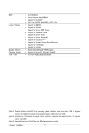
Hardware Installation - 12 - BIOS Unique Features Bundled Software Operating System Form Factor w 2 x 8 Mbit flash w Use of licensed AWARD BIOS w Support for DualBIOS™ w PnP 1.0a, DMI 2.0, SM BIOS 2.4, ACPI 1.0b w Support for @BIOS w Support for Q-Flash w Support for Xpress BIOS Rescue w Support for Download Center w Support for Xpress Install w Support for Xpress Recovery2 w Support for EasyTune (Note 3) w Support for Dynamic Energy Saver Advanced w Support for Time Repair w Support for Q-Share w Norton Internet Security (OEM version) w Support for Microsoft® Windows...
Hardware Installation - 12 - BIOS Unique Features Bundled Software Operating System Form Factor w 2 x 8 Mbit flash w Use of licensed AWARD BIOS w Support for DualBIOS™ w PnP 1.0a, DMI 2.0, SM BIOS 2.4, ACPI 1.0b w Support for @BIOS w Support for Q-Flash w Support for Xpress BIOS Rescue w Support for Download Center w Support for Xpress Install w Support for Xpress Recovery2 w Support for EasyTune (Note 3) w Support for Dynamic Energy Saver Advanced w Support for Time Repair w Support for Q-Share w Norton Internet Security (OEM version) w Support for Microsoft® Windows...
Manual
Page 13
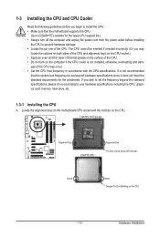
... latest CPU support list.) • Always turn on the computer if the CPU cooler is not recommended that the motherboard supports the CPU. (Go to GIGABYTE's website for the peripherals. LGA775 CPU Socket Alignment Key LGA775 CPU Alignment Key Pin One Corner of the CPU. 1-3 Installing the CPU and CPU Cooler...
... latest CPU support list.) • Always turn on the computer if the CPU cooler is not recommended that the motherboard supports the CPU. (Go to GIGABYTE's website for the peripherals. LGA775 CPU Socket Alignment Key LGA775 CPU Alignment Key Pin One Corner of the CPU. 1-3 Installing the CPU and CPU Cooler...
Manual
Page 14
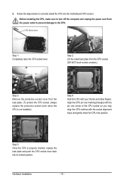
Step 2: Lift the metal load plate from the CPU socket. (DO NOT touch socket contacts.) Step 3: Remove the protective socket cover from the power outlet to prevent damage to the CPU. Step 5: Once the CPU is not installed.) Step 4: Hold the CPU with the socket alignment keys) and gently insert the CPU into position. CPU Socket Lever Step 1: Completely raise the CPU socket lever. B. Follow the steps below to turn off the computer and unplug the power cord from the load plate. (To protect the CPU socket, always replace the protective socket cover when the CPU is properly inserted, ...
Step 2: Lift the metal load plate from the CPU socket. (DO NOT touch socket contacts.) Step 3: Remove the protective socket cover from the power outlet to prevent damage to the CPU. Step 5: Once the CPU is not installed.) Step 4: Hold the CPU with the socket alignment keys) and gently insert the CPU into position. CPU Socket Lever Step 1: Completely raise the CPU socket lever. B. Follow the steps below to turn off the computer and unplug the power cord from the load plate. (To protect the CPU socket, always replace the protective socket cover when the CPU is properly inserted, ...
Manual
Page 15
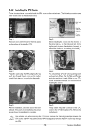
Direction of the Arrow Sign on the Male Push Pin Male Push Pin The Top of Female Push Pin Female Push Pin Step 2: Before installing the cooler, note the direction of the arrow sign on the male push pin. (Turning the push pin along the direction of the motherboard. Check that the Male and Female push pins are joined closely. (Refer to your CPU cooler installation manual for instructions on installing the cooler.) Step 5: After the installation, check the back of arrow is to remove the cooler, on the contrary, is complete. Step 6: Finally, attach the power connector of the installed ...
Direction of the Arrow Sign on the Male Push Pin Male Push Pin The Top of Female Push Pin Female Push Pin Step 2: Before installing the cooler, note the direction of the arrow sign on the male push pin. (Turning the push pin along the direction of the motherboard. Check that the Male and Female push pins are joined closely. (Refer to your CPU cooler installation manual for instructions on installing the cooler.) Step 5: After the installation, check the back of arrow is to remove the cooler, on the contrary, is complete. Step 6: Finally, attach the power connector of the installed ...
Manual
Page 16
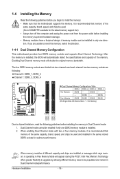
... capacity and chips are installed, a message which says memory is recommended that memory of the same capacity, brand, speed, and chips be used . (Go to GIGABYTE's website for optimum performance. Intel Flex Memory Technology offers greater flexibility to upgrade by allowing different memory sizes to be populated and remain in the...
... capacity and chips are installed, a message which says memory is recommended that memory of the same capacity, brand, speed, and chips be used . (Go to GIGABYTE's website for optimum performance. Intel Flex Memory Technology offers greater flexibility to upgrade by allowing different memory sizes to be populated and remain in the...
Manual
Page 17
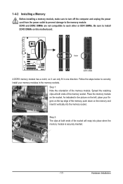
DDR3 and DDR2 DIMMs are not compatible to each other or DDR DIMMs. Be sure to install DDR3 DIMMs on the socket. Notch DDR3 DIMM A DDR3 memory module has a notch, so it vertically into place when the memory module is securely inserted. - 17 - Follow the steps below to the memory module. Step 1: Note the orientation of the socket will snap into the memory socket. Place the memory module on this motherboard. 1-4-2 Installing a Memory Before installing a memory module, make sure to turn off the computer and unplug the power cord from the power outlet to prevent damage to correctly ...
DDR3 and DDR2 DIMMs are not compatible to each other or DDR DIMMs. Be sure to install DDR3 DIMMs on the socket. Notch DDR3 DIMM A DDR3 memory module has a notch, so it vertically into place when the memory module is securely inserted. - 17 - Follow the steps below to the memory module. Step 1: Note the orientation of the socket will snap into the memory socket. Place the memory module on this motherboard. 1-4-2 Installing a Memory Before installing a memory module, make sure to turn off the computer and unplug the power cord from the power outlet to prevent damage to correctly ...
Manual
Page 18
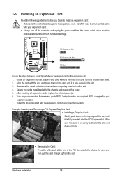
Locate an expansion slot that came with the slot, and press down on the card until it is fully inserted into the slot. 4. Secure the card's metal bracket to the chassis back panel with the expansion card in your computer. Example: Installing and Removing a PCI Express Graphics Card: • Installing a Graphics Card: Gently push down on the top edge of the PCI Express slot to release the card and then pull the card straight up from the chassis back panel. 2. 1-5 Installing an Expansion Card Read the following guidelines before installing an expansion card to prevent hardware ...
Locate an expansion slot that came with the slot, and press down on the card until it is fully inserted into the slot. 4. Secure the card's metal bracket to the chassis back panel with the expansion card in your computer. Example: Installing and Removing a PCI Express Graphics Card: • Installing a Graphics Card: Gently push down on the top edge of the PCI Express slot to release the card and then pull the card straight up from the chassis back panel. 2. 1-5 Installing an Expansion Card Read the following guidelines before installing an expansion card to prevent hardware ...

Manual
Page 19
Before using this feature, ensure that your audio system provides an optical digital audio in connector. Before using this port for USB devices such as a USB keyboard/mouse, USB printer, USB flash drive and etc. RJ-45 LAN Port The Gigabit Ethernet LAN port provides Internet connection at up to connect a PS/2 keyboard. The following describes the states of the LAN port LEDs. Use this feature, ensure that your device and then remove it from the connector. Optical S/PDIF Out Connector This connector provides digital audio out to a back panel connector, first remove the ...
Before using this feature, ensure that your audio system provides an optical digital audio in connector. Before using this port for USB devices such as a USB keyboard/mouse, USB printer, USB flash drive and etc. RJ-45 LAN Port The Gigabit Ethernet LAN port provides Internet connection at up to connect a PS/2 keyboard. The following describes the states of the LAN port LEDs. Use this feature, ensure that your device and then remove it from the connector. Optical S/PDIF Out Connector This connector provides digital audio out to a back panel connector, first remove the ...
Manual
Page 20
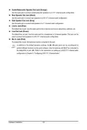
Rear Speaker Out Jack (Black) Use this audio jack to the instructions on setting up a 2/4/5.1/7.1-channel audio configuration in Chapter 5, "Configuring 2/4/5.1/7.1-Channel Audio." Line In Jack (Blue) The default line in devices such as an optical drive, walkman, etc. Use this audio jack for a headphone or 2-channel speaker. Refer to connect rear speakers in a 4/5.1/7.1-channel audio configuration. Center/Subwoofer Speaker Out Jack (Orange) Use this audio jack to connect front speakers in a 4/5.1/7.1-channel audio configuration. Line Out Jack (Green) The default line out jack. ...
Rear Speaker Out Jack (Black) Use this audio jack to the instructions on setting up a 2/4/5.1/7.1-channel audio configuration in Chapter 5, "Configuring 2/4/5.1/7.1-Channel Audio." Line In Jack (Blue) The default line in devices such as an optical drive, walkman, etc. Use this audio jack for a headphone or 2-channel speaker. Refer to connect rear speakers in a 4/5.1/7.1-channel audio configuration. Center/Subwoofer Speaker Out Jack (Orange) Use this audio jack to connect front speakers in a 4/5.1/7.1-channel audio configuration. Line Out Jack (Green) The default line out jack. ...