
Manual
Page 4
Table of Contents Box Contents ...6 OptionalItems...6 GA-EP35-DS3L/S3L Motherboard Layout 7 Block Diagram...8 Chapter 1 Hardware Installation 9 1-1 Installation Precautions 9 1-2 Product Specifications 10 1-3 Installing the CPU and CPU Cooler 13 1-3-1 Installing the CPU 13 1-3-2 Installing the CPU Cooler 15 1-4 Installing the Memory 16 1-4-1 Dual Channel Memory Configuration 16 1-4-2 Installing a Memory 17 1-5 Installing an Expansion Card 18 1-6 Back Panel Connectors...
Table of Contents Box Contents ...6 OptionalItems...6 GA-EP35-DS3L/S3L Motherboard Layout 7 Block Diagram...8 Chapter 1 Hardware Installation 9 1-1 Installation Precautions 9 1-2 Product Specifications 10 1-3 Installing the CPU and CPU Cooler 13 1-3-1 Installing the CPU 13 1-3-2 Installing the CPU Cooler 15 1-4 Installing the Memory 16 1-4-1 Dual Channel Memory Configuration 16 1-4-2 Installing a Memory 17 1-5 Installing an Expansion Card 18 1-6 Back Panel Connectors...

Manual
Page 6
...-01R) S/PDIF in cable (Part No. 12CR1-1SPDIN-01R) - 6 - The box contents are for reference only. Box Contents GA-EP35-DS3L or GA-EP35-S3L motherboard Motherboard driver disk User's Manual Quick Installation Guide Intel® LGA775 CPU Installation Guide One IDE cable and one floppy disk drive cable Two SATA 3Gb/s cables I/O Shield • The...
...-01R) S/PDIF in cable (Part No. 12CR1-1SPDIN-01R) - 6 - The box contents are for reference only. Box Contents GA-EP35-DS3L or GA-EP35-S3L motherboard Motherboard driver disk User's Manual Quick Installation Guide Intel® LGA775 CPU Installation Guide One IDE cable and one floppy disk drive cable Two SATA 3Gb/s cables I/O Shield • The...

Manual
Page 8
Block Diagram PCIe CLK (100 MHz) LGA775 Processor CPU CLK+/(333/266/200 MHz) PCI Express x16 LAN ATA-133/100/66/33 IDE Channel JMicron 368 PCI Express Bus x 1 RJ45 RTL 8111B x1 3 PCI Express x1 x 1 x 1 x 1 PCIe CLK (100 MHz) PCI Bus Host Interface DDR2 1066/800/667 MHz Intel® P35 Dual Channel Memory MCH CLK (333/266/200 MHz) Intel® ICH9 BIOS 4 SATA 3Gb/s 12 USB Ports CODEC IT8718 Floppy LPT Port COM Port PS/2 KB/Mouse Surround Speaker Out Center/Subwoofer Speaker Out Side Speaker Out MIC Line-Out Line-In SPDIF In SPDIF Out 3 PCI PCI CLK (33 MHz) - 8 -
Block Diagram PCIe CLK (100 MHz) LGA775 Processor CPU CLK+/(333/266/200 MHz) PCI Express x16 LAN ATA-133/100/66/33 IDE Channel JMicron 368 PCI Express Bus x 1 RJ45 RTL 8111B x1 3 PCI Express x1 x 1 x 1 x 1 PCIe CLK (100 MHz) PCI Bus Host Interface DDR2 1066/800/667 MHz Intel® P35 Dual Channel Memory MCH CLK (333/266/200 MHz) Intel® ICH9 BIOS 4 SATA 3Gb/s 12 USB Ports CODEC IT8718 Floppy LPT Port COM Port PS/2 KB/Mouse Surround Speaker Out Center/Subwoofer Speaker Out Side Speaker Out MIC Line-Out Line-In SPDIF In SPDIF Out 3 PCI PCI CLK (33 MHz) - 8 -

Manual
Page 9
.... • Prior to installing the motherboard, please have a problem related to wear an electrostatic discharge (ESD) wrist strap when handling electronic components such as a motherboard, CPU or memory. These stickers are connected. • To prevent damage to the motherboard, do not have an ESD wrist strap, keep your dealer.
.... • Prior to installing the motherboard, please have a problem related to wear an electrostatic discharge (ESD) wrist strap when handling electronic components such as a motherboard, CPU or memory. These stickers are connected. • To prevent damage to the motherboard, do not have an ESD wrist strap, keep your dealer.

Manual
Page 10
...; 4 processor Extreme Edition/Intel® Pentium® 4 processor/ Intel® Celeron® processor in the LGA 775 package (Go to GIGABYTE's website for the latest CPU support list.) Š L2 cache varies with CPU Š 1333/1066/800 MHz FSB Š North Bridge: Intel® P35 Express Chipset Š South Bridge: Intel®... the South Bridge Š Up to 12 USB 2.0/1.1 ports (6 on the back panel, 6 via the USB brackets connected to the internal USB headers) "*" Only the GA-EP35-DS3L adopts All-Solid Capacitor design. GA-EP35-DS3L/S3L Motherboard - 10 -
...; 4 processor Extreme Edition/Intel® Pentium® 4 processor/ Intel® Celeron® processor in the LGA 775 package (Go to GIGABYTE's website for the latest CPU support list.) Š L2 cache varies with CPU Š 1333/1066/800 MHz FSB Š North Bridge: Intel® P35 Express Chipset Š South Bridge: Intel®... the South Bridge Š Up to 12 USB 2.0/1.1 ports (6 on the back panel, 6 via the USB brackets connected to the internal USB headers) "*" Only the GA-EP35-DS3L adopts All-Solid Capacitor design. GA-EP35-DS3L/S3L Motherboard - 10 -

Manual
Page 11
... Š 1 x 4-pin ATX 12V power connector Š 1 x floppy disk drive connector Š 1 x IDE connector Š 4 x SATA 3Gb/s connectors Š 1 x CPU fan header Š 2 x system fan headers Š 1 x power fan header Š 1 x front panel header Š 1 x front panel audio header Š 1 x... iTE IT8718 chip Hardware Monitor Š System voltage detection Š CPU/System temperature detection Š CPU/System/Power fan speed detection Š CPU overheating warning Š CPU/System/Power fan fail warning Š CPU fan speed control (Note 3) BIOS Š 1 x 8 Mbit ...
... Š 1 x 4-pin ATX 12V power connector Š 1 x floppy disk drive connector Š 1 x IDE connector Š 4 x SATA 3Gb/s connectors Š 1 x CPU fan header Š 2 x system fan headers Š 1 x power fan header Š 1 x front panel header Š 1 x front panel audio header Š 1 x... iTE IT8718 chip Hardware Monitor Š System voltage detection Š CPU/System temperature detection Š CPU/System/Power fan speed detection Š CPU overheating warning Š CPU/System/Power fan fail warning Š CPU fan speed control (Note 3) BIOS Š 1 x 8 Mbit ...
Manual
Page 12
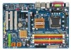
GA-EP35-DS3L/S3L Motherboard - 12 - Unique Features Bundled Software Operating System Form Factor Š Support for @BIOS Š Support for Download Center Š Support for Q-Flash Š ... SATA connectors for AHCI mode. (Refer to Chapter 2, "BIOS Setup," "Integrated Peripherals," for details on enabling AHCI.) (Note 3) Whether the CPU fan speed control function is supported will depend on the CPU cooler you install. (Note 4) Available functions in Easytune may differ by motherboard model. (Note 5) Due to the hardware limitation, you...
GA-EP35-DS3L/S3L Motherboard - 12 - Unique Features Bundled Software Operating System Form Factor Š Support for @BIOS Š Support for Download Center Š Support for Q-Flash Š ... SATA connectors for AHCI mode. (Refer to Chapter 2, "BIOS Setup," "Integrated Peripherals," for details on enabling AHCI.) (Note 3) Whether the CPU fan speed control function is supported will depend on the CPU cooler you install. (Note 4) Available functions in Easytune may differ by motherboard model. (Note 5) Due to the hardware limitation, you...
Manual
Page 13
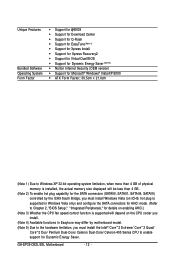
... keys on the motherboard CPU socket and the notches on the CPU - 13 - Hardware Installation mended that the motherboard supports the CPU. (Go to GIGABYTE's website for the peripherals. LGA775 CPU Socket Alignment Key LGA 775 CPU Alignment Key Pin One Corner of the CPU may locate the notches on... both sides of the CPU and alignment keys on the CPU socket.) • Apply an even...
... keys on the motherboard CPU socket and the notches on the CPU - 13 - Hardware Installation mended that the motherboard supports the CPU. (Go to GIGABYTE's website for the peripherals. LGA775 CPU Socket Alignment Key LGA 775 CPU Alignment Key Pin One Corner of the CPU may locate the notches on... both sides of the CPU and alignment keys on the CPU socket.) • Apply an even...

Manual
Page 14
... index fingers. Follow the steps below to the CPU. Step 2: Remove the protective socket cover. B. GA-EP35-DS3L/S3L Motherboard - 14 - Step 3: Lift the metal load plate on the CPU socket. Step 4: Hold the CPU with the socket alignment keys) and gently insert the CPU into position. Step 5: Once the CPU is properly inserted, replace the load plate...
... index fingers. Follow the steps below to the CPU. Step 2: Remove the protective socket cover. B. GA-EP35-DS3L/S3L Motherboard - 14 - Step 3: Lift the metal load plate on the CPU socket. Step 4: Hold the CPU with the socket alignment keys) and gently insert the CPU into position. Step 5: Once the CPU is properly inserted, replace the load plate...
Manual
Page 15
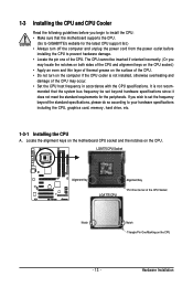
... Finally, attach the power connector of arrow is to remove the cooler, on the contrary, is to install.) Step 3: Place the cooler atop the CPU, aligning the four push pins through the pin holes on the motherboard. Direction of the Arrow Sign on the Male Push Pin Male Push Pin... cooler.) Step 1: Apply an even and thin layer of thermal grease on the surface of the motherboard. 1-3-2 Installing the CPU Cooler Follow the steps below to correctly install the CPU cooler on the motherboard. (The following procedure uses Intel® boxed cooler as the picture above, the installation is complete...
... Finally, attach the power connector of arrow is to remove the cooler, on the contrary, is to install.) Step 3: Place the cooler atop the CPU, aligning the four push pins through the pin holes on the motherboard. Direction of the Arrow Sign on the Male Push Pin Male Push Pin... cooler.) Step 1: Apply an even and thin layer of thermal grease on the surface of the motherboard. 1-3-2 Installing the CPU Cooler Follow the steps below to correctly install the CPU cooler on the motherboard. (The following procedure uses Intel® boxed cooler as the picture above, the installation is complete...

Manual
Page 22
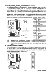
... the power connector, first make sure the power supply is compatible with power supplies with 2x10 power connectors. Connect the power supply cable to the CPU. When using a 2x10 power supply. 3 4 1 2 ATX_12V ATX_12V: Pin No. 1 2 3 4 Definition GND GND +12V +12V 12 24 1 13 ATX ATX: Pin No. 1 2 3 4 5 6 7 8 9 ...-12V GND PS_ON(soft On/Off) GND GND GND -5V +5V +5V +5V (Only for 2x12-pinATX) GND (Only for 2x12-pin ATX) GA-EP35-DS3L/S3L Motherboard - 22 - Do not insert the power supply cable into pins under the protective cover when using a 2x12 power supply, remove the protective ...
... the power connector, first make sure the power supply is compatible with power supplies with 2x10 power connectors. Connect the power supply cable to the CPU. When using a 2x10 power supply. 3 4 1 2 ATX_12V ATX_12V: Pin No. 1 2 3 4 Definition GND GND +12V +12V 12 24 1 13 ATX ATX: Pin No. 1 2 3 4 5 6 7 8 9 ...-12V GND PS_ON(soft On/Off) GND GND GND -5V +5V +5V +5V (Only for 2x12-pinATX) GND (Only for 2x12-pin ATX) GA-EP35-DS3L/S3L Motherboard - 22 - Do not insert the power supply cable into pins under the protective cover when using a 2x12 power supply, remove the protective ...
Manual
Page 23
...to locate pin 1 of floppy disk drives supported are not configuration jumper blocks. 3/4/5/6) CPU_FAN/SYS_FAN1/SYS_FAN2/PWR_FAN (Fan Headers) The motherboard has a 4-pin CPU fan header (CPU_FAN), a 3-pin system fan header (SYS_FAN1), a 4-pin system fan header (SYS_FAN2) and a 3-pin power fan header (PWR_FAN). When ...KB, 720 KB, 1.2 MB, 1.44 MB, and 2.88 MB. Most fans are designed with fan speed control design. The pin 1 of a CPU fan with color- Each fan header supplies a +12V power voltage and possesses a foolproof insertion design. The types of the connector and the floppy disk...
...to locate pin 1 of floppy disk drives supported are not configuration jumper blocks. 3/4/5/6) CPU_FAN/SYS_FAN1/SYS_FAN2/PWR_FAN (Fan Headers) The motherboard has a 4-pin CPU fan header (CPU_FAN), a 3-pin system fan header (SYS_FAN1), a 4-pin system fan header (SYS_FAN2) and a 3-pin power fan header (PWR_FAN). When ...KB, 720 KB, 1.2 MB, 1.44 MB, and 2.88 MB. Most fans are designed with fan speed control design. The pin 1 of a CPU fan with color- Each fan header supplies a +12V power voltage and possesses a foolproof insertion design. The types of the connector and the floppy disk...
Manual
Page 30
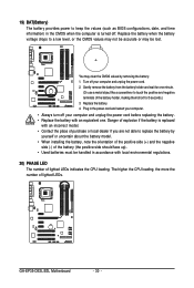
... of the positive side (+) and the negative side (-) of the battery (the positive side should face up). • Used batteries must be lost. GA-EP35-DS3L/S3L Motherboard - 30 - You may be handled in the power cord and restart your computer. • Always turn off your computer and unplug the... power cord. 2. Gently remove the battery from the battery holder and wait for 5 seconds.) 3. The higher the CPU loading, the more the number of the battery holder, making them short for one . Replace the battery. 4. Danger of explosion if the battery is...
... of the positive side (+) and the negative side (-) of the battery (the positive side should face up). • Used batteries must be lost. GA-EP35-DS3L/S3L Motherboard - 30 - You may be handled in the power cord and restart your computer. • Always turn off your computer and unplug the... power cord. 2. Gently remove the battery from the battery holder and wait for 5 seconds.) 3. The higher the CPU loading, the more the number of the battery holder, making them short for one . Replace the battery. 4. Danger of explosion if the battery is...

Manual
Page 34
...view the BIOS settings but not to make changes in effect. First enter the profile name (to erase the default profile name, use this task.) GA-EP35-DS3L/S3L Motherboard - 34 - A supervisor password allows you to make changes. „ Save & Exit Setup Save all the changes made in the ... Use this menu to configure the system's PCI & PnP resources. „ PC Health Status Use this menu to see information about autodetected system/CPU temperature, system voltage and fan speed, etc. „ MB Intelligent Tweaker(M.I.T.) Use this menu to configure all changes and the previous settings remain...
...view the BIOS settings but not to make changes in effect. First enter the profile name (to erase the default profile name, use this task.) GA-EP35-DS3L/S3L Motherboard - 34 - A supervisor password allows you to make changes. „ Save & Exit Setup Save all the changes made in the ... Use this menu to configure the system's PCI & PnP resources. „ PC Health Status Use this menu to see information about autodetected system/CPU temperature, system voltage and fan speed, etc. „ MB Intelligent Tweaker(M.I.T.) Use this menu to configure all changes and the previous settings remain...
Manual
Page 37
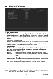
...USB-FDD, USB-ZIP, USB-CDROM, USB-HDD, Legacy LAN, Disabled. BIOS Setup to 3 (Note) No-Execute Memory Protect (Note) CPU Enhanced Halt (C1E) (Note) CPU Thermal Monitor 2(TM2) (Note) CPU EIST Function (Note) Virtualization Technology (Note) [Disabled] [Disabled] [Enabled] [Enabled] [Enabled] [Enabled] [Enabled] Full Screen LOGO Show...only required for entering the BIOS Setup program. (Default) A password is required every time the system boots, or only when you install a CPU that supports this feature. Use the up or down arrow key to select a hard drive, then press the plus key (or ) or...
...USB-FDD, USB-ZIP, USB-CDROM, USB-HDD, Legacy LAN, Disabled. BIOS Setup to 3 (Note) No-Execute Memory Protect (Note) CPU Enhanced Halt (C1E) (Note) CPU Thermal Monitor 2(TM2) (Note) CPU EIST Function (Note) Virtualization Technology (Note) [Disabled] [Disabled] [Enabled] [Enabled] [Enabled] [Enabled] [Enabled] Full Screen LOGO Show...only required for entering the BIOS Setup program. (Default) A password is required every time the system boots, or only when you install a CPU that supports this feature. Use the up or down arrow key to select a hard drive, then press the plus key (or ) or...

Manual
Page 38
...system; With virtualization, one computer system can dynamically and effectively lower the CPU voltage and core frequency to Disabled for the computer, reducing exposure to limit CPUID maximum value. GA-EP35-DS3L/S3L Motherboard - 38 - Disabled displays normal POST message. (Default: ... Enables or disables Intel® CPU Enhanced Halt (C1E) function, a CPU power-saving function in independent partitions. Set this feature. When enabled, the CPU core frequency and voltage will be reduced during system halt state to display the GIGABYTE Logo at system startup. to ...
...system; With virtualization, one computer system can dynamically and effectively lower the CPU voltage and core frequency to Disabled for the computer, reducing exposure to limit CPUID maximum value. GA-EP35-DS3L/S3L Motherboard - 38 - Disabled displays normal POST message. (Default: ... Enables or disables Intel® CPU Enhanced Halt (C1E) function, a CPU power-saving function in independent partitions. Set this feature. When enabled, the CPU core frequency and voltage will be reduced during system halt state to display the GIGABYTE Logo at system startup. to ...
Manual
Page 45
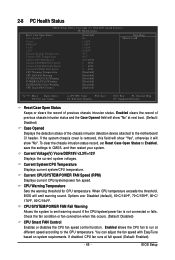
... chassis intrusion detection device attached to the motherboard CI header. Current Voltage(V) Vcore/DDR18V/+3.3V/+12V Displays the current system voltages. CPU/SYSTEM/POWER FAN Fail Warning Allows the system to CMOS, and then restart your system. Check the fan condition or fan connection... BIOS Setup If the system chassis cover is not connected or fails. Current CPU/SYSTEM/POWER FAN Speed (RPM) Displays current CPU/system/power fan speed. Enabled allows the CPU fan to the CPU temperature. If disabled, CPU fan runs at different speed according to run at full speed. (Default: ...
... chassis intrusion detection device attached to the motherboard CI header. Current Voltage(V) Vcore/DDR18V/+3.3V/+12V Displays the current system voltages. CPU/SYSTEM/POWER FAN Fail Warning Allows the system to CMOS, and then restart your system. Check the fan condition or fan connection... BIOS Setup If the system chassis cover is not connected or fails. Current CPU/SYSTEM/POWER FAN Speed (RPM) Displays current CPU/system/power fan speed. Enabled allows the CPU fan to the CPU temperature. If disabled, CPU fan runs at different speed according to run at full speed. (Default: ...

Manual
Page 46
...these components. 2-9 MB Intelligent Tweaker(M.I.T.) CMOS Setup Utility-Copyright (C) 1984-2007 Award Software MB Intelligent Tweaker(M.I.T.) Robust Graphics Booster CPU Clock Ratio (Note) Fine CPU Clock Ratio (Note) CPU Frequency CPU Host Clock Control x CPU Host Frequency (Mhz) PCI Express Frequency (Mhz) C.I.A. 2 Performance Enhance System Memory Multiplier (SPD) Memory Frequency (Mhz) ...ESC: Exit F1: General Help F7: Optimized Defaults • Incorrectly doing overclock/overvoltage may result in damage to boot. If this feature. GA-EP35-DS3L/S3L Motherboard - 46 -
...these components. 2-9 MB Intelligent Tweaker(M.I.T.) CMOS Setup Utility-Copyright (C) 1984-2007 Award Software MB Intelligent Tweaker(M.I.T.) Robust Graphics Booster CPU Clock Ratio (Note) Fine CPU Clock Ratio (Note) CPU Frequency CPU Host Clock Control x CPU Host Frequency (Mhz) PCI Express Frequency (Mhz) C.I.A. 2 Performance Enhance System Memory Multiplier (SPD) Memory Frequency (Mhz) ...ESC: Exit F1: General Help F7: Optimized Defaults • Incorrectly doing overclock/overvoltage may result in damage to boot. If this feature. GA-EP35-DS3L/S3L Motherboard - 46 -

Manual
Page 47
...Important It is highly recommended that supports this item to maximize system performance. The adjustable range is highly dependent on CPU loading. C.I .A.2. (Default) Cruise Increases CPU frequency by 7% or 9% depending on your system bus to 700 MHz. Disabled Disables the use of C.I .A.2 ...to manually set this item to alter the clock ratio for the installed CPU. Turbo Increases CPU frequency by 17% or 19% depending on CPU loading. mode based on CPU loading. Full Thrust Increases CPU frequency by 15% or 17% depending on system configurations. The adjustable...
...Important It is highly recommended that supports this item to maximize system performance. The adjustable range is highly dependent on CPU loading. C.I .A.2. (Default) Cruise Increases CPU frequency by 7% or 9% depending on your system bus to 700 MHz. Disabled Disables the use of C.I .A.2 ...to manually set this item to alter the clock ratio for the installed CPU. Turbo Increases CPU frequency by 17% or 19% depending on CPU loading. mode based on CPU loading. Full Thrust Increases CPU frequency by 15% or 17% depending on system configurations. The adjustable...
Manual
Page 48
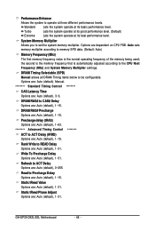
... 1~31. Rank Write to ACT Delay Options are : Auto (default), 1~31. Refresh to READ Delay Options are dependent on CPU FSB. System Memory Multiplier Allows you to be configurable. DRAM Timing Selectable (SPD) Manual allows all DRAM Timing items below to ...(Mhz) The first memory frequency value is automatically adjusted according to operate at its basic performance level. GA-EP35-DS3L/S3L Motherboard - 48 - Performance Enhance Allows the system to the CPU Host Frequency (Mhz) and System Memory Multiplier settings. DRAM RAS# Precharge Options are: Auto (default), ...
... 1~31. Rank Write to ACT Delay Options are : Auto (default), 1~31. Refresh to READ Delay Options are dependent on CPU FSB. System Memory Multiplier Allows you to be configurable. DRAM Timing Selectable (SPD) Manual allows all DRAM Timing items below to ...(Mhz) The first memory frequency value is automatically adjusted according to operate at its basic performance level. GA-EP35-DS3L/S3L Motherboard - 48 - Performance Enhance Allows the system to the CPU Host Frequency (Mhz) and System Memory Multiplier settings. DRAM RAS# Precharge Options are: Auto (default), ...


