Manual
Page 1
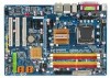
GA-EP35-DS3L/ GA-EP35-S3L LGA775 socket motherboard for Intel® CoreTM processor family/ Intel® Pentium® processor family/Intel® Celeron® processor family User's Manual Rev. 1002 12ME-EP35DS3L-1002R
GA-EP35-DS3L/ GA-EP35-S3L LGA775 socket motherboard for Intel® CoreTM processor family/ Intel® Pentium® processor family/Intel® Celeron® processor family User's Manual Rev. 1002 12ME-EP35DS3L-1002R
Manual
Page 3
... the following types of documentations: „ For quick set-up of GIGABYTE. Documentation Classifications In order to use of GIGABYTE branded motherboards. GIGABYTE UNITED INC. is protected by GIGABYTE without GIGABYTE's prior written permission. sive global distributor of this manual is designated by GIGA-BYTE TECHNOLOGY CO., LTD. Example: Copyright © 2008 GIGA-BYTE TECHNOLOGY CO...
... the following types of documentations: „ For quick set-up of GIGABYTE. Documentation Classifications In order to use of GIGABYTE branded motherboards. GIGABYTE UNITED INC. is protected by GIGABYTE without GIGABYTE's prior written permission. sive global distributor of this manual is designated by GIGA-BYTE TECHNOLOGY CO., LTD. Example: Copyright © 2008 GIGA-BYTE TECHNOLOGY CO...

Manual
Page 6
...-1UB030-51R) 2-port SATA power cable (Part No. 12CF1-2SERPW-01R) S/PDIF in cable (Part No. 12CR1-1SPDIN-01R) - 6 - Box Contents GA-EP35-DS3L or GA-EP35-S3L motherboard Motherboard driver disk User's Manual Quick Installation Guide Intel® LGA775 CPU Installation Guide One IDE cable and one floppy disk drive cable Two SATA 3Gb/s cables...
...-1UB030-51R) 2-port SATA power cable (Part No. 12CF1-2SERPW-01R) S/PDIF in cable (Part No. 12CR1-1SPDIN-01R) - 6 - Box Contents GA-EP35-DS3L or GA-EP35-S3L motherboard Motherboard driver disk User's Manual Quick Installation Guide Intel® LGA775 CPU Installation Guide One IDE cable and one floppy disk drive cable Two SATA 3Gb/s cables...

Manual
Page 9
... standard. • Before using the product, please verify that all cables and power connectors of electrostatic discharge (ESD). Prior to installation, carefully read the user's manual and follow these procedures: • Prior to installation, do not remove or break motherboard S/N (Serial Number) sticker or warranty sticker provided by unplugging the power...
... standard. • Before using the product, please verify that all cables and power connectors of electrostatic discharge (ESD). Prior to installation, carefully read the user's manual and follow these procedures: • Prior to installation, do not remove or break motherboard S/N (Serial Number) sticker or warranty sticker provided by unplugging the power...
Manual
Page 15
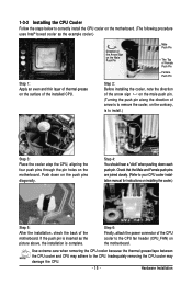
... the power connector of the motherboard. Hardware Installation Check that the Male and Female push pins are joined closely. (Refer to your CPU cooler installation manual for instructions on installing the cooler.) Step 5: After the installation, check the back of the CPU cooler to install.) Step 3: Place the cooler atop the...
... the power connector of the motherboard. Hardware Installation Check that the Male and Female push pins are joined closely. (Refer to your CPU cooler installation manual for instructions on installing the cooler.) Step 5: After the installation, check the back of the CPU cooler to install.) Step 3: Place the cooler atop the...

Manual
Page 18
... into the slot. 4. Turn on the card until it is securely seated in the slot. 3. If necessary, go to BIOS Setup to prevent hardware damage. GA-EP35-DS3L/S3L Motherboard - 18 - Align the card with your computer. After installing all expansion cards, replace the chassis cover(s). 6. Make sure the card is fully seated... Card: Gently push back on the lever on the slot and then lift the card straight out from the chassis back panel. 2. Carefully read the manual that supports your expansion card(s). 7.
... into the slot. 4. Turn on the card until it is securely seated in the slot. 3. If necessary, go to BIOS Setup to prevent hardware damage. GA-EP35-DS3L/S3L Motherboard - 18 - Align the card with your computer. After installing all expansion cards, replace the chassis cover(s). 6. Make sure the card is fully seated... Card: Gently push back on the lever on the slot and then lift the card straight out from the chassis back panel. 2. Carefully read the manual that supports your expansion card(s). 7.

Manual
Page 28
... cards) for digital audio output from the HDMI display at the same time. For information about connecting the S/PDIF digital audio cable, carefully read the manual for your computer and unplug the power cord from the power outlet to prevent damage to certain expansion cards like graphics cards and sound cards... not plug the IEEE 1394 bracket (2x5-pin) cable into the USB header. • Prior to installing the USB bracket, be sure to USB 2.0/1.1 specification. GA-EP35-DS3L/S3L Motherboard - 28 - Each USB header can provide two USB ports via an optional USB bracket.
... cards) for digital audio output from the HDMI display at the same time. For information about connecting the S/PDIF digital audio cable, carefully read the manual for your computer and unplug the power cord from the power outlet to prevent damage to certain expansion cards like graphics cards and sound cards... not plug the IEEE 1394 bracket (2x5-pin) cable into the USB header. • Prior to installing the USB bracket, be sure to USB 2.0/1.1 specification. GA-EP35-DS3L/S3L Motherboard - 28 - Each USB header can provide two USB ports via an optional USB bracket.

Manual
Page 29
... do so may cause damage to the motherboard. • After system restart, go to BIOS Setup to load factory defaults (select Load Optimized Defaults) or manually configure the BIOS settings (refer to touch the two pins for BIOS configurations). - 29 - Pin No. Hardware Installation
... do so may cause damage to the motherboard. • After system restart, go to BIOS Setup to load factory defaults (select Load Optimized Defaults) or manually configure the BIOS settings (refer to touch the two pins for BIOS configurations). - 29 - Pin No. Hardware Installation

Manual
Page 35
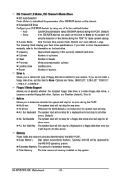
BIOS Setup The date format is 13:0:0. Select the desired field and use the up arrow or down arrow key to set to manually enter the specifications of the hard drive when the hard drive access mode is set the time. For example, 1 p.m. is week (read-only), month, ...one of the three methods below: • Auto • None Lets BIOS automatically detect IDE/SATA devices during the POST for faster system startup. • Manual Allows you to CHS. IDE Channel 0, 1 Master IDE HDD Auto-Detection Press to None so the system will skip the detection of the IDE/SATA...
BIOS Setup The date format is 13:0:0. Select the desired field and use the up arrow or down arrow key to set to manually enter the specifications of the hard drive when the hard drive access mode is set the time. For example, 1 p.m. is week (read-only), month, ...one of the three methods below: • Auto • None Lets BIOS automatically detect IDE/SATA devices during the POST for faster system startup. • Manual Allows you to CHS. IDE Channel 0, 1 Master IDE HDD Auto-Detection Press to None so the system will skip the detection of the IDE/SATA...
Manual
Page 36
...720K/3.5", 1.44M/3.5", 2.88M/3.5". No Errors The system boot will stop for the MS-DOS operating system. Base Memory Also called conventional memory. GA-EP35-DS3L/S3L Motherboard - 36 - If you to autodetect the parameters of the IDE/SATA device on the system. Head Number of sectors. Options...boot will be reserved for any error. Capacity Approximate capacity of extended memory. Drive A Allows you wish to enter the parameters manually, refer to specify whether the installed floppy disk drive is 3-mode floppy disk drive, a Japanese standard floppy disk drive. ...
...720K/3.5", 1.44M/3.5", 2.88M/3.5". No Errors The system boot will stop for the MS-DOS operating system. Base Memory Also called conventional memory. GA-EP35-DS3L/S3L Motherboard - 36 - If you to autodetect the parameters of the IDE/SATA device on the system. Head Number of sectors. Options...boot will be reserved for any error. Capacity Approximate capacity of extended memory. Drive A Allows you wish to enter the parameters manually, refer to specify whether the installed floppy disk drive is 3-mode floppy disk drive, a Japanese standard floppy disk drive. ...

Manual
Page 46
...PCI-E OverVoltage Control FSB OverVoltage Control (G)MCH OverVoltage Control CPU Voltage Control Normal CPU Vcore 2 4 20 2 4 13 ******** Auto Auto Auto Auto Auto Auto [Manual] [Normal] [Normal] [Normal] [Normal] [Normal] 1.30000V Item Help Menu Level` KLJI: Move Enter: Select F5: Previous Values +/-/PU/PD: Value ...occurs, clear the CMOS values and reset the board to CPU, chipset, or memory and reduce the useful life of these components. GA-EP35-DS3L/S3L Motherboard - 46 - This page is recommended that you set the System Voltage Control item to Auto to optimize the system voltage ...
...PCI-E OverVoltage Control FSB OverVoltage Control (G)MCH OverVoltage Control CPU Voltage Control Normal CPU Vcore 2 4 20 2 4 13 ******** Auto Auto Auto Auto Auto Auto [Manual] [Normal] [Normal] [Normal] [Normal] [Normal] 1.30000V Item Help Menu Level` KLJI: Move Enter: Select F5: Previous Values +/-/PU/PD: Value ...occurs, clear the CMOS values and reset the board to CPU, chipset, or memory and reduce the useful life of these components. GA-EP35-DS3L/S3L Motherboard - 46 - This page is recommended that you set the System Voltage Control item to Auto to optimize the system voltage ...

Manual
Page 47
... CMOS values to reset the board to default values. (Default: Disabled) CPU Host Frequency (Mhz) Allows you to manually set this item to automatically set the CPU host frequency. CPU Frequency Displays the current operating CPU frequency. CPU Host Clock... is enabled. Note: System stability varies, depending on system components, when system instability occurs after overclocking, please wait for 20 seconds to manually set the R.G.B. Disabled Disables the use of your system hardware components. Turbo Increases CPU frequency by 7% or 9% depending on system configurations....
... CMOS values to reset the board to default values. (Default: Disabled) CPU Host Frequency (Mhz) Allows you to manually set this item to automatically set the CPU host frequency. CPU Frequency Displays the current operating CPU frequency. CPU Host Clock... is enabled. Note: System stability varies, depending on system components, when system instability occurs after overclocking, please wait for 20 seconds to manually set the R.G.B. Disabled Disables the use of your system hardware components. Turbo Increases CPU frequency by 7% or 9% depending on system configurations....
Manual
Page 48
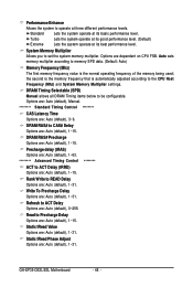
...), 3~6. Precharge delay (tRAS) Options are: Auto (default), 1~63. ******** Advanced Timing Control ******** ACT to ACT Delay (tRRD) Options are : Auto (default), 1~31. GA-EP35-DS3L/S3L Motherboard - 48 - DRAM Timing Selectable (SPD) Manual allows all DRAM Timing items below to set the system memory multiplier. Static tRead Phase Adjust Options are : Auto (default), 1~15. Performance...
...), 3~6. Precharge delay (tRAS) Options are: Auto (default), 1~63. ******** Advanced Timing Control ******** ACT to ACT Delay (tRRD) Options are : Auto (default), 1~31. GA-EP35-DS3L/S3L Motherboard - 48 - DRAM Timing Selectable (SPD) Manual allows all DRAM Timing items below to set the system memory multiplier. Static tRead Phase Adjust Options are : Auto (default), 1~15. Performance...

Manual
Page 49
... FSB voltage by 0.1V to 0.7V at 0.1V increment. (G)MCH OverVoltage Control Allows you to set the North Bridge voltage. Manual allows all voltage control items below to be configurable. (Default: Manual) DDR2 OverVoltage Control Allows you to set memory voltage. The adjustable range is dependent on the CPU being installed. (Default... 0.1V to 0.3V at 0.1V increment. CPU Voltage Control Allows you to set the CPU voltage. ******** System Voltage Optimized ******** System Voltage Control Determines whether to manually set the system voltages as required.
... FSB voltage by 0.1V to 0.7V at 0.1V increment. (G)MCH OverVoltage Control Allows you to set the North Bridge voltage. Manual allows all voltage control items below to be configurable. (Default: Manual) DDR2 OverVoltage Control Allows you to set memory voltage. The adjustable range is dependent on the CPU being installed. (Default... 0.1V to 0.3V at 0.1V increment. CPU Voltage Control Allows you to set the CPU voltage. ******** System Voltage Optimized ******** System Voltage Control Determines whether to manually set the system voltages as required.

Manual
Page 55
Drivers Installation 3-4 Hardware Information This page provides information about the hardware devices on this motherboard. 3-5 Contact Us Check the contacts information of the GIGABYTE headquarter in Taiwan and the overseas branch offices on the last page of this manual. - 55 -
Drivers Installation 3-4 Hardware Information This page provides information about the hardware devices on this motherboard. 3-5 Contact Us Check the contacts information of the GIGABYTE headquarter in Taiwan and the overseas branch offices on the last page of this manual. - 55 -

Manual
Page 66
F1) obtained from GIGABYTE's website and follow the instructions in "Update the BIOS without Using the Internet Update ...Load Optimized Defaults and press to load BIOS defaults. 3. Select Load Optimized Defaults and press to load BIOS defaults. ep35ds3l. GA-EP35-DS3L/S3L Motherboard - 66 - Update the BIOS without Using the Internet Update Function" below. Select the location where you save the...your system. Step 3: First make sure the model name on the @BIOS server site, please manually download the BIOS update file from the Internet or through other Step 3: source.
F1) obtained from GIGABYTE's website and follow the instructions in "Update the BIOS without Using the Internet Update ...Load Optimized Defaults and press to load BIOS defaults. 3. Select Load Optimized Defaults and press to load BIOS defaults. ep35ds3l. GA-EP35-DS3L/S3L Motherboard - 66 - Update the BIOS without Using the Internet Update Function" below. Select the location where you save the...your system. Step 3: First make sure the model name on the @BIOS server site, please manually download the BIOS update file from the Internet or through other Step 3: source.

Manual
Page 71
... following instructions use Windows XP as the example operating system.) Step 1: After installing the audio driver, the Audio Manager icon will appear in jack and manually configure the jack for microphone functionality. • If your operating system has been updated with the latest Service Pack for Windows. (Note) 2/4/5.1/7.1-Channel Audio Configurations...
... following instructions use Windows XP as the example operating system.) Step 1: After installing the audio driver, the Audio Manager icon will appear in jack and manually configure the jack for microphone functionality. • If your operating system has been updated with the latest Service Pack for Windows. (Note) 2/4/5.1/7.1-Channel Audio Configurations...

Manual
Page 81
... we will help you can drop off your waste equipment for recycling, please contact your local government office, your product's user's manual and we at the time of printing. Under the Directive, used for any responsibility for errors or omissions in this document is... RoHS (Restriction of electric and electronic devices and their components. Contravention will fulfill the national laws as most of the materials in all GIGABYTE motherboards fulfill European Union regulations for recycling. Š If you need further assistance in recycling, reusing in your "end of life" ...
... we will help you can drop off your waste equipment for recycling, please contact your local government office, your product's user's manual and we at the time of printing. Under the Directive, used for any responsibility for errors or omissions in this document is... RoHS (Restriction of electric and electronic devices and their components. Contravention will fulfill the national laws as most of the materials in all GIGABYTE motherboards fulfill European Union regulations for recycling. Š If you need further assistance in recycling, reusing in your "end of life" ...


