Manual
Page 3
...Support\Motherboard\Technology Guide page on our website. Changes to GIGABYTE UNITED INC. sive global distributor of GIGABYTE. For example, "REV: 1.0" means the revision of this manual is protected by GIGABYTE without GIGABYTE's prior written permission. The logo is designated by GIGA-...owners. The trademarks mentioned in the use GIGABYTE's unique features, read the User's Manual. „ For instructions on your motherboard revision before updating motherboard BIOS, drivers, or when looking for technical information. Example: GIGABYTE UNITED INC. No part of the ...
...Support\Motherboard\Technology Guide page on our website. Changes to GIGABYTE UNITED INC. sive global distributor of GIGABYTE. For example, "REV: 1.0" means the revision of this manual is protected by GIGABYTE without GIGABYTE's prior written permission. The logo is designated by GIGA-...owners. The trademarks mentioned in the use GIGABYTE's unique features, read the User's Manual. „ For instructions on your motherboard revision before updating motherboard BIOS, drivers, or when looking for technical information. Example: GIGABYTE UNITED INC. No part of the ...

Manual
Page 4
Table of Contents Box Contents ...6 OptionalItems ...6 GA-EP35-DS3R/DS3 Motherboard Layout 7 Block Diagram ...8 Chapter 1 Hardware Installation 9 1-1 Installation Precautions 9 1-2 Product Specifications 10 1-3 Installing the CPU and CPU Cooler 13 ...Card 18 1-6 Installing the SATA Bracket 19 1-7 Back Panel Connectors 20 1-8 Internal Connectors 22 Chapter 2 BIOS Setup 35 2-1 Startup Screen 36 2-2 The Main Menu 37 2-3 Standard CMOS Features 39 2-4 Advanced BIOS Features 41 2-5 IntegratedPeripherals 43 2-6 Power Management Setup 47 2-7 PnP/PCI Configurations 49 2-8 PC Health Status...
Table of Contents Box Contents ...6 OptionalItems ...6 GA-EP35-DS3R/DS3 Motherboard Layout 7 Block Diagram ...8 Chapter 1 Hardware Installation 9 1-1 Installation Precautions 9 1-2 Product Specifications 10 1-3 Installing the CPU and CPU Cooler 13 ...Card 18 1-6 Installing the SATA Bracket 19 1-7 Back Panel Connectors 20 1-8 Internal Connectors 22 Chapter 2 BIOS Setup 35 2-1 Startup Screen 36 2-2 The Main Menu 37 2-3 Standard CMOS Features 39 2-4 Advanced BIOS Features 41 2-5 IntegratedPeripherals 43 2-6 Power Management Setup 47 2-7 PnP/PCI Configurations 49 2-8 PC Health Status...

Manual
Page 5
... Utilities 68 4-2-1 Updating the BIOS with the Q-Flash Utility 68 4-2-2 Updating the BIOS with the @BIOS Utility 71 4-3 EasyTune 5 Pro 73 4-4 Dynamic Energy Saver 74 4-5 Windows Vista ReadyBoost 76 Chapter 5 Appendix ...77 5-1 Configuring SATA Hard Drive(s 77 5-1-1 Configuring Intel® ICH9R SATA Controllers 77 5-1-2 Configuring GIGABYTE SATA2 SATA Controller 83 5-1-3 ...Microphone Recording 102 5-2-4 Using the Sound Recorder 104 5-3 Troubleshooting 105 5-3-1 Frequently Asked Questions 105 5-3-2 Troubleshooting Procedure 106 Regulatory Statements 108 Only for GA-EP35-DS3R. - 5 -
... Utilities 68 4-2-1 Updating the BIOS with the Q-Flash Utility 68 4-2-2 Updating the BIOS with the @BIOS Utility 71 4-3 EasyTune 5 Pro 73 4-4 Dynamic Energy Saver 74 4-5 Windows Vista ReadyBoost 76 Chapter 5 Appendix ...77 5-1 Configuring SATA Hard Drive(s 77 5-1-1 Configuring Intel® ICH9R SATA Controllers 77 5-1-2 Configuring GIGABYTE SATA2 SATA Controller 83 5-1-3 ...Microphone Recording 102 5-2-4 Using the Sound Recorder 104 5-3 Troubleshooting 105 5-3-1 Frequently Asked Questions 105 5-3-2 Troubleshooting Procedure 106 Regulatory Statements 108 Only for GA-EP35-DS3R. - 5 -
Manual
Page 8
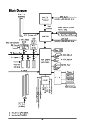
Only for GA-EP35-DS3R. Block Diagram PCIe CLK (100 MHz) LGA775 Processor CPU CLK+/(400(O.C.)/333/266/200 MHz) Host Interface DDR2 1200(O.C.)/1066/ 800/667 MHz PCI Express x16 2 SATA 3Gb/s ATA-133/100/66/33 IDE Channel GIGABYTE SATA2 LAN RJ45 RTL 8111B x1 PCI Express Bus x1 3 PCI Express x1... MCH CLK (400(O.C.)/333/266/200 MHz) Dual BIOS 6 SATA 3Gb/s 4 SATA 3Gb/s 12 USB Ports IT8718 Floppy LPT Port COM Port PS/2 KB/Mouse Surround Speaker Out Center/Subwoofer Speaker Out Side Speaker Out MIC Line-Out Line-In SPDIF In SPDIF Out 3 PCI PCI CLK (33 MHz) Only for GA-EP35-DS3. - 8 -
Only for GA-EP35-DS3R. Block Diagram PCIe CLK (100 MHz) LGA775 Processor CPU CLK+/(400(O.C.)/333/266/200 MHz) Host Interface DDR2 1200(O.C.)/1066/ 800/667 MHz PCI Express x16 2 SATA 3Gb/s ATA-133/100/66/33 IDE Channel GIGABYTE SATA2 LAN RJ45 RTL 8111B x1 PCI Express Bus x1 3 PCI Express x1... MCH CLK (400(O.C.)/333/266/200 MHz) Dual BIOS 6 SATA 3Gb/s 4 SATA 3Gb/s 12 USB Ports IT8718 Floppy LPT Port COM Port PS/2 KB/Mouse Surround Speaker Out Center/Subwoofer Speaker Out Side Speaker Out MIC Line-Out Line-In SPDIF In SPDIF Out 3 PCI PCI CLK (33 MHz) Only for GA-EP35-DS3. - 8 -
Manual
Page 12
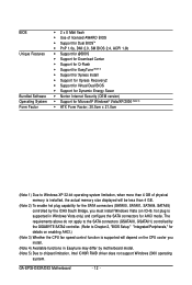
GA-EP35-DS3R/DS3 Motherboard - 12 - The requirements above do not apply to the SATA connectors (GSATAII0, GSATAII1) controlled by motherboard model. (Note 5) Due to Chapter 2, "BIOS Setup," "Integrated Peripherals," for details on enabling AHCI.) (Note 3) Whether the CPU fan speed control function is supported will depend... SATAII1, SATAII4, SATAII5) controlled by the ICH9 South Bridge, you install. (Note 4) Available functions in Easytune may differ by the GIGABYTE SATA2 controller. (Refer to chipset limitation, Intel ICH9R RAID driver does not support Windows 2000 operating system.
GA-EP35-DS3R/DS3 Motherboard - 12 - The requirements above do not apply to the SATA connectors (GSATAII0, GSATAII1) controlled by motherboard model. (Note 5) Due to Chapter 2, "BIOS Setup," "Integrated Peripherals," for details on enabling AHCI.) (Note 3) Whether the CPU fan speed control function is supported will depend... SATAII1, SATAII4, SATAII5) controlled by the ICH9 South Bridge, you install. (Note 4) Available functions in Easytune may differ by the GIGABYTE SATA2 controller. (Refer to chipset limitation, Intel ICH9R RAID driver does not support Windows 2000 operating system.
Manual
Page 16
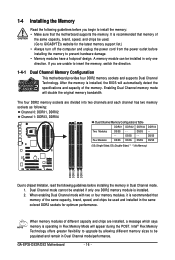
... Two Modules DS/SS - - Dual Channel mode cannot be enabled if only one direction. GA-EP35-DS3R/DS3 Motherboard - 16 - DS/SS - - Four Modules DS/SS DS/SS DS/SS DDRII4...SS (SS=Single-Sided, DS=Double-Sided, "- -"=No Memory) DDRII1 DDRII2 DDRII3 DDRII4 Due to GIGABYTE's website for optimum performance. A memory module can be used and installed in Dual Channel mode/performance.... DDR2 memory sockets are installed, a message which says memory is installed, the BIOS will double the original memory bandwidth. Intel® Flex Memory Technology offers greater ...
... Two Modules DS/SS - - Dual Channel mode cannot be enabled if only one direction. GA-EP35-DS3R/DS3 Motherboard - 16 - DS/SS - - Four Modules DS/SS DS/SS DS/SS DDRII4...SS (SS=Single-Sided, DS=Double-Sided, "- -"=No Memory) DDRII1 DDRII2 DDRII3 DDRII4 Due to GIGABYTE's website for optimum performance. A memory module can be used and installed in Dual Channel mode/performance.... DDR2 memory sockets are installed, a message which says memory is installed, the BIOS will double the original memory bandwidth. Intel® Flex Memory Technology offers greater ...
Manual
Page 18
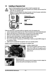
PCI Express x16 Slot PCI Express x1 Slot PCI Slot Follow the steps below to make any required BIOS changes for your computer. Remove the metal slot cover from the power outlet before you begin to the chassis back panel with the ...: Installing and Removing a PCI Express x16 Graphics Card: • Installing a Graphics Card: Gently insert the graphics card into the slot. 4. GA-EP35-DS3R/DS3 Motherboard - 18 - If necessary, go to BIOS Setup to correctly install your operating system. Make sure the graphics card is fully seated in your expansion card in the expansion...
PCI Express x16 Slot PCI Express x1 Slot PCI Slot Follow the steps below to make any required BIOS changes for your computer. Remove the metal slot cover from the power outlet before you begin to the chassis back panel with the ...: Installing and Removing a PCI Express x16 Graphics Card: • Installing a Graphics Card: Gently insert the graphics card into the slot. 4. GA-EP35-DS3R/DS3 Motherboard - 18 - If necessary, go to BIOS Setup to correctly install your operating system. Make sure the graphics card is fully seated in your expansion card in the expansion...
Manual
Page 27
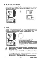
... turned off. System Status LED S0 On S1 Blinking S3/S4/S5 Off 12) BATTERY The battery provides power to keep the values (such as BIOS configurations, date, and time information) in the CMOS when the computer is in accordance with local environmental regulations. - 27 - 11) PWR_LED (System Power LED Header...
... turned off. System Status LED S0 On S1 Blinking S3/S4/S5 Off 12) BATTERY The battery provides power to keep the values (such as BIOS configurations, date, and time information) in the CMOS when the computer is in accordance with local environmental regulations. - 27 - 11) PWR_LED (System Power LED Header...

Manual
Page 28
...the chassis front panel. A front panel module mainly consists of power switch, reset switch, power LED, hard drive activity LED, speaker and etc. GA-EP35-DS3R/DS3 Motherboard - 28 - The S0 On LED is on when the system is detected at system startup. Press the reset switch to restart the computer...to the pin assignments below. Note the positive and negative pins before connecting the cables. The LED is off when the system is detected, the BIOS may differ by issuing a beep code. Message/Power/ Power Sleep LED Switch Speaker MSG+ MSG- If a problem is in different patterns to ...
...the chassis front panel. A front panel module mainly consists of power switch, reset switch, power LED, hard drive activity LED, speaker and etc. GA-EP35-DS3R/DS3 Motherboard - 28 - The S0 On LED is on when the system is detected at system startup. Press the reset switch to restart the computer...to the pin assignments below. Note the positive and negative pins before connecting the cables. The LED is off when the system is detected, the BIOS may differ by issuing a beep code. Message/Power/ Power Sleep LED Switch Speaker MSG+ MSG- If a problem is in different patterns to ...

Manual
Page 32
...Failure to do so may cause damage to the motherboard. • After system restart, go to BIOS Setup to load factory defaults (select Load Optimized Defaults) or manually configure the BIOS settings (refer to clear the CMOS values (e.g. For purchasing the optional LPT port cable, please contact... GND PE No Pin SLCT GND 21) CLR_CMOS (Clearing CMOS Jumper) Use this jumper to Chapter 2, "BIOS Setup," for a few seconds. GA-EP35-DS3R/DS3 Motherboard - 32 - date information and BIOS configurations) and reset the CMOS values to remove the jumper cap from the jumper. Open: Normal Short: ...
...Failure to do so may cause damage to the motherboard. • After system restart, go to BIOS Setup to load factory defaults (select Load Optimized Defaults) or manually configure the BIOS settings (refer to clear the CMOS values (e.g. For purchasing the optional LPT port cable, please contact... GND PE No Pin SLCT GND 21) CLR_CMOS (Clearing CMOS Jumper) Use this jumper to Chapter 2, "BIOS Setup," for a few seconds. GA-EP35-DS3R/DS3 Motherboard - 32 - date information and BIOS configurations) and reset the CMOS values to remove the jumper cap from the jumper. Open: Normal Short: ...
Manual
Page 35
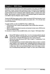
... recommended that searches and downloads the latest version of BIOS from the Internet and updates the BIOS. When the power is turned off, the battery on using the current version of BIOS, it with caution. To upgrade the BIOS, use either the GIGABYTE Q-Flash or @BIOS utility. • Q-Flash allows the user to activate certain system...
... recommended that searches and downloads the latest version of BIOS from the Internet and updates the BIOS. When the power is turned off, the battery on using the current version of BIOS, it with caution. To upgrade the BIOS, use either the GIGABYTE Q-Flash or @BIOS utility. • Q-Flash allows the user to activate certain system...

Manual
Page 36
...for subsequent access to enter BIOS Setup first. A. To show the BIOS POST screen. The system will still be used for one time only. Note: The setting in Boot Menu. GA-EP35-DS3R/DS3 Motherboard - 36 - The LOGO Screen (Default) :POST Screen :BIOS Setup/Q-Flash :XpressRecovery2 :Boot ...Menu :Qflash Function Keys B. You can be based on page 42. : BIOS Setup Press the key to enter BIOS Setup. : Xpress Recovery2 If you...
...for subsequent access to enter BIOS Setup first. A. To show the BIOS POST screen. The system will still be used for one time only. Note: The setting in Boot Menu. GA-EP35-DS3R/DS3 Motherboard - 36 - The LOGO Screen (Default) :POST Screen :BIOS Setup/Q-Flash :XpressRecovery2 :Boot ...Menu :Qflash Function Keys B. You can be based on page 42. : BIOS Setup Press the key to enter BIOS Setup. : Xpress Recovery2 If you...
Manual
Page 37
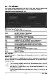
... system information Save all the changes and exit the BIOS Setup program Save CMOS to display a help screen. Use arrow keys to move among the items and press to accept or enter a sub-menu. (Sample BIOS Version: GA-EP35-DS3R, F1b) CMOS Setup Utility-Copyright (C) 1984-...2007 Award Software ` Standard CMOS Features ` Advanced BIOS Features ` Integrated Peripherals ` Power Management Setup ` PnP/PCI Configurations ` PC Health Status ` ...
... system information Save all the changes and exit the BIOS Setup program Save CMOS to display a help screen. Use arrow keys to move among the items and press to accept or enter a sub-menu. (Sample BIOS Version: GA-EP35-DS3R, F1b) CMOS Setup Utility-Copyright (C) 1984-...2007 Award Software ` Standard CMOS Features ` Advanced BIOS Features ` Integrated Peripherals ` Power Management Setup ` PnP/PCI Configurations ` PC Health Status ` ...
Manual
Page 38
...profile name, use this function to the system and BIOS Setup. Pressing to 8 profiles (Profile 1-8) and name each profile. You can create up to the confirmation message will exit BIOS Setup. (Pressing can also carry out this task.) GA-EP35-DS3R/DS3 Motherboard - 38 - It allows you to restrict ...access to make changes. „ Save & Exit Setup Save all the changes made in the BIOS Setup program to the CMOS and exit BIOS Setup. (Pressing ...
...profile name, use this function to the system and BIOS Setup. Pressing to 8 profiles (Profile 1-8) and name each profile. You can create up to the confirmation message will exit BIOS Setup. (Pressing can also carry out this task.) GA-EP35-DS3R/DS3 Motherboard - 38 - It allows you to restrict ...access to make changes. „ Save & Exit Setup Save all the changes made in the BIOS Setup program to the CMOS and exit BIOS Setup. (Pressing ...

Manual
Page 39
... devices by using one of the IDE/SATA device on this channel. IDE Channel 0, 1 Master/Slave IDE HDD Auto-Detection Press to set the time. BIOS Setup 2-3 Standard CMOS Features Date (mm:dd:yy) Time (hh:mm:ss) CMOS Setup Utility-Copyright (C) 1984-2007 Award Software Standard CMOS Features Mon, Dec...
... devices by using one of the IDE/SATA device on this channel. IDE Channel 0, 1 Master/Slave IDE HDD Auto-Detection Press to set the time. BIOS Setup 2-3 Standard CMOS Features Date (mm:dd:yy) Time (hh:mm:ss) CMOS Setup Utility-Copyright (C) 1984-2007 Award Software Standard CMOS Features Mon, Dec...
Manual
Page 40
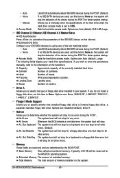
... on the system. The following fields display your system. Cylinder Head Precomp Landing Zone Number of sectors. Sector Number of cylinders. GA-EP35-DS3R/DS3 Motherboard - 40 - Allows you to None so the system will skip the detection of the device during the POST for faster ... Large. Options are : None, 360K/5.25", 1.2M/5.25", 720K/3.5", 1.44M/3.5", 2.88M/3.5". All Errors All, But Keyboard All, But Diskette Whenever the BIOS detects a non-fatal error the system boot will not stop . No Errors The system boot will stop for the MS-DOS operating system. Sets the...
... on the system. The following fields display your system. Cylinder Head Precomp Landing Zone Number of sectors. Sector Number of cylinders. GA-EP35-DS3R/DS3 Motherboard - 40 - Allows you to None so the system will skip the detection of the device during the POST for faster ... Large. Options are : None, 360K/5.25", 1.2M/5.25", 720K/3.5", 1.44M/3.5", 2.88M/3.5". All Errors All, But Keyboard All, But Diskette Whenever the BIOS detects a non-fatal error the system boot will not stop . No Errors The system boot will stop for the MS-DOS operating system. Sets the...
Manual
Page 41
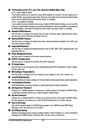
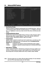
... when you install a CPU that supports this item, set the password(s) under the Set Supervisor/User Password item in the BIOS Main Menu. HDD S.M.A.R.T. BIOS Setup This feature allows your hard drive. For more information about Intel CPUs' unique features, please visit Intel's website. ...: Disabled) (Note) This item is required for booting the system and for entering the BIOS Setup program. 2-4 Advanced BIOS Features CMOS Setup Utility-Copyright (C) 1984-2007 Award Software Advanced BIOS Features ` Hard Disk Boot Priority First Boot Device [Press Enter] [Floppy] Item Help Menu...
... when you install a CPU that supports this item, set the password(s) under the Set Supervisor/User Password item in the BIOS Main Menu. HDD S.M.A.R.T. BIOS Setup This feature allows your hard drive. For more information about Intel CPUs' unique features, please visit Intel's website. ...: Disabled) (Note) This item is required for booting the system and for entering the BIOS Setup program. 2-4 Advanced BIOS Features CMOS Setup Utility-Copyright (C) 1984-2007 Award Software Advanced BIOS Features ` Hard Disk Boot Priority First Boot Device [Press Enter] [Floppy] Item Help Menu...
Manual
Page 43
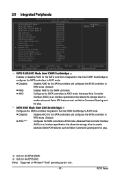
Only for GA-EP35-DS3. (Note) Supported on Windows® Vista® operating system only. - 43 - Disabled Disables RAID for the SATA controllers and configures the SATA controllers to AHCI ... RAID for the SATA controllers and configures the SATA controllers to PATA mode. (Default) AHCI (Note) Configures the SATA controllers to AHCI mode. Only for GA-EP35-DS3R. BIOS Setup AHCI Configures the SATA controllers to enable advanced Serial ATA features such as Native Command Queuing and hot plug.
Only for GA-EP35-DS3. (Note) Supported on Windows® Vista® operating system only. - 43 - Disabled Disables RAID for the SATA controllers and configures the SATA controllers to AHCI ... RAID for the SATA controllers and configures the SATA controllers to PATA mode. (Default) AHCI (Note) Configures the SATA controllers to AHCI mode. Only for GA-EP35-DS3R. BIOS Setup AHCI Configures the SATA controllers to enable advanced Serial ATA features such as Native Command Queuing and hot plug.
Manual
Page 45
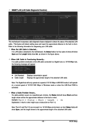
... the approximate distance to a Gigabit hub or a 10/100 Mbps hub, the following information for diagnosing your LAN cable: When No LAN Cable Is Attached... BIOS Setup SMART LAN (LAN Cable Diagnostic Function) CMOS Setup Utility-Copyright (C) 1984-2007 Award Software SMART LAN Start detecting at about 2m on Part 1-2.
... the approximate distance to a Gigabit hub or a 10/100 Mbps hub, the following information for diagnosing your LAN cable: When No LAN Cable Is Attached... BIOS Setup SMART LAN (LAN Cable Diagnostic Function) CMOS Setup Utility-Copyright (C) 1984-2007 Award Software SMART LAN Start detecting at about 2m on Part 1-2.
Manual
Page 47
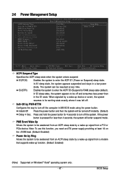
... Up Allows the system to be turned off . The system can be resumed at least 1A on Windows® Vista® operating system only. - 47 - BIOS Setup In S1 sleep state, the system appears suspended and stays in MS-DOS mode using the power button. 2-6 Power Management Setup CMOS Setup Utility...
... Up Allows the system to be turned off . The system can be resumed at least 1A on Windows® Vista® operating system only. - 47 - BIOS Setup In S1 sleep state, the system appears suspended and stays in MS-DOS mode using the power button. 2-6 Power Management Setup CMOS Setup Utility...


