
Manual
Page 4
Table of Contents Box Contents ...6 OptionalItems ...6 GA-EP35-DS3R/DS3 Motherboard Layout 7 Block Diagram ...8 Chapter 1 Hardware Installation 9 1-1 Installation Precautions 9 1-2 Product Specifications 10 1-3 Installing the CPU and CPU Cooler 13 1-3-1 Installing the CPU 13 1-3-2 Installing the CPU Cooler 15 1-4 Installing the Memory 16 1-4-1 Dual Channel Memory Configuration 16 1-4-2 Installing a Memory 17 1-5 Installing an Expansion Card 18 1-6 Installing the SATA...
Table of Contents Box Contents ...6 OptionalItems ...6 GA-EP35-DS3R/DS3 Motherboard Layout 7 Block Diagram ...8 Chapter 1 Hardware Installation 9 1-1 Installation Precautions 9 1-2 Product Specifications 10 1-3 Installing the CPU and CPU Cooler 13 1-3-1 Installing the CPU 13 1-3-2 Installing the CPU Cooler 15 1-4 Installing the Memory 16 1-4-1 Dual Channel Memory Configuration 16 1-4-2 Installing a Memory 17 1-5 Installing an Expansion Card 18 1-6 Installing the SATA...
Manual
Page 6
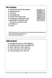
...-01R) - 6 - The box contents are for reference only. Box Contents GA-EP35-DS3R or GA-EP35-DS3 motherboard Motherboard driver disk User's Manual Quick Installation Guide Intel® LGA775 CPU Installation Guide One IDE cable and one floppy disk drive cable GA-EP35-DS3R: Four SATA 3Gb/s cables GA-EP35-DS3: Two SATA 3Gb/s cables One SATA bracket I/O Shield • The...
...-01R) - 6 - The box contents are for reference only. Box Contents GA-EP35-DS3R or GA-EP35-DS3 motherboard Motherboard driver disk User's Manual Quick Installation Guide Intel® LGA775 CPU Installation Guide One IDE cable and one floppy disk drive cable GA-EP35-DS3R: Four SATA 3Gb/s cables GA-EP35-DS3: Two SATA 3Gb/s cables One SATA bracket I/O Shield • The...
Manual
Page 8
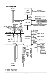
Block Diagram PCIe CLK (100 MHz) LGA775 Processor CPU CLK+/(400(O.C.)/333/266/200 MHz) Host Interface DDR2 1200(O.C.)/1066/ 800/667 MHz PCI Express x16 2 SATA 3Gb/s ATA-133/100/66/33 IDE Channel GIGABYTE SATA2 LAN RJ45 RTL 8111B x1 PCI Express Bus x1 3 PCI Express x1 x 1 x 1 x 1 PCIe CLK (100 MHz... Speaker Out Center/Subwoofer Speaker Out Side Speaker Out MIC Line-Out Line-In SPDIF In SPDIF Out 3 PCI PCI CLK (33 MHz) Only for GA-EP35-DS3. - 8 - Only for GA-EP35-DS3R.
Block Diagram PCIe CLK (100 MHz) LGA775 Processor CPU CLK+/(400(O.C.)/333/266/200 MHz) Host Interface DDR2 1200(O.C.)/1066/ 800/667 MHz PCI Express x16 2 SATA 3Gb/s ATA-133/100/66/33 IDE Channel GIGABYTE SATA2 LAN RJ45 RTL 8111B x1 PCI Express Bus x1 3 PCI Express x1 x 1 x 1 x 1 PCIe CLK (100 MHz... Speaker Out Center/Subwoofer Speaker Out Side Speaker Out MIC Line-Out Line-In SPDIF In SPDIF Out 3 PCI PCI CLK (33 MHz) Only for GA-EP35-DS3. - 8 - Only for GA-EP35-DS3R.

Manual
Page 9
.... • It is best to come in a high-temperature environment. • Turning on the computer power during the installation process can become damaged as a motherboard, CPU or memory.
.... • It is best to come in a high-temperature environment. • Turning on the computer power during the installation process can become damaged as a motherboard, CPU or memory.
Manual
Page 10
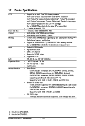
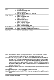
... RAID 5, and RAID 10 Š GIGABYTE SATA2 chip: - 1 x IDE connector supporting ATA-133/100/66/33 and up to 2 IDE devices - 2 x SATA 3Gb/s connectors (GSATAII0, GSATAII1) supporting up to 4 SATA 3Gb/s devices(Note 2) - Only for GA-EP35-DS3. 1-2 Product Specifications CPU Front Side Bus Chipset Memory Audio LAN ...174; Pentium® 4 processor/ Intel® Celeron® processor in the LGA 775 package (Go to GIGABYTE's website for the latest CPU support list.) Š L2 cache varies with CPU Š 1600(O.C.)/1333/1066/800 MHz FSB Š North Bridge: Intel® P35 Express Chipset Š...
... RAID 5, and RAID 10 Š GIGABYTE SATA2 chip: - 1 x IDE connector supporting ATA-133/100/66/33 and up to 2 IDE devices - 2 x SATA 3Gb/s connectors (GSATAII0, GSATAII1) supporting up to 4 SATA 3Gb/s devices(Note 2) - Only for GA-EP35-DS3. 1-2 Product Specifications CPU Front Side Bus Chipset Memory Audio LAN ...174; Pentium® 4 processor/ Intel® Celeron® processor in the LGA 775 package (Go to GIGABYTE's website for the latest CPU support list.) Š L2 cache varies with CPU Š 1600(O.C.)/1333/1066/800 MHz FSB Š North Bridge: Intel® P35 Express Chipset Š...
Manual
Page 11
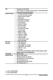
Only for GA-EP35-DS3R. Hardware Installation USB Š ...; 1 x floppy disk drive connector Š 1 x IDE connector Š 8 x SATA 3Gb/s connectors Š 6 x SATA 3Gb/s connectors Š 1 x CPU fan header Š 2 x system fan headers Š 1 x power fan header Š 1 x front panel header Š 1 x front panel audio header &#... voltage detection Š CPU/System temperature detection Š CPU/System/Power fan speed detection Š CPU overheating warning Š CPU/System/Power fan fail warning Š CPU fan speed control (Note 3) Only for GA-EP35-DS3. - 11 -
Only for GA-EP35-DS3R. Hardware Installation USB Š ...; 1 x floppy disk drive connector Š 1 x IDE connector Š 8 x SATA 3Gb/s connectors Š 6 x SATA 3Gb/s connectors Š 1 x CPU fan header Š 2 x system fan headers Š 1 x power fan header Š 1 x front panel header Š 1 x front panel audio header &#... voltage detection Š CPU/System temperature detection Š CPU/System/Power fan speed detection Š CPU overheating warning Š CPU/System/Power fan fail warning Š CPU fan speed control (Note 3) Only for GA-EP35-DS3. - 11 -
Manual
Page 12
...the SATA connectors (GSATAII0, GSATAII1) controlled by the GIGABYTE SATA2 controller. (Refer to Chapter 2, "BIOS Setup," "Integrated Peripherals," for details on enabling AHCI.) (Note 3) Whether the CPU fan speed control function is supported in Easytune may ...CPU cooler you install. (Note 4) Available functions in Windows Vista only) and configure the SATA connectors for the SATA connectors (SATAII0, SATAII1, SATAII4, SATAII5) controlled by motherboard model. (Note 5) Due to chipset limitation, Intel ICH9R RAID driver does not support Windows 2000 operating system. GA-EP35-DS3R/DS3...
...the SATA connectors (GSATAII0, GSATAII1) controlled by the GIGABYTE SATA2 controller. (Refer to Chapter 2, "BIOS Setup," "Integrated Peripherals," for details on enabling AHCI.) (Note 3) Whether the CPU fan speed control function is supported in Easytune may ...CPU cooler you install. (Note 4) Available functions in Windows Vista only) and configure the SATA connectors for the SATA connectors (SATAII0, SATAII1, SATAII4, SATAII5) controlled by motherboard model. (Note 5) Due to chipset limitation, Intel ICH9R RAID driver does not support Windows 2000 operating system. GA-EP35-DS3R/DS3...
Manual
Page 13
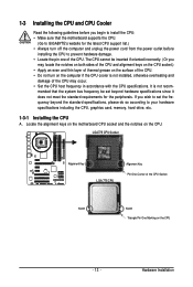
...CPU. (Go to GIGABYTE's website for the peripherals. Hardware Installation 1-3 Installing the CPU and CPU Cooler Read the following guidelines before installing the CPU to your hardware specifications including the CPU, graphics card, memory, hard drive, etc. 1-3-1 Installing the CPU A. Locate the alignment keys on the motherboard CPU socket and the notches on the CPU - 13 - The CPU...off the computer and unplug the power cord from the power outlet before you begin to install the CPU: • Make sure that the system bus frequency be inserted if oriented incorrectly. (Or you...
...CPU. (Go to GIGABYTE's website for the peripherals. Hardware Installation 1-3 Installing the CPU and CPU Cooler Read the following guidelines before installing the CPU to your hardware specifications including the CPU, graphics card, memory, hard drive, etc. 1-3-1 Installing the CPU A. Locate the alignment keys on the motherboard CPU socket and the notches on the CPU - 13 - The CPU...off the computer and unplug the power cord from the power outlet before you begin to install the CPU: • Make sure that the system bus frequency be inserted if oriented incorrectly. (Or you...

Manual
Page 14
... properly inserted, replace the load plate and push the CPU socket lever back into the motherboard CPU socket. Step 2: Remove the protective socket cover. GA-EP35-DS3R/DS3 Motherboard - 14 - Step 4: Hold the CPU with the socket alignment keys) and gently insert the CPU into position. Before installing the CPU, make sure to turn off the computer and...
... properly inserted, replace the load plate and push the CPU socket lever back into the motherboard CPU socket. Step 2: Remove the protective socket cover. GA-EP35-DS3R/DS3 Motherboard - 14 - Step 4: Hold the CPU with the socket alignment keys) and gently insert the CPU into position. Before installing the CPU, make sure to turn off the computer and...
Manual
Page 15
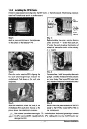
... as the picture above, the installation is complete. Step 4: You should hear a "click" when pushing down on the surface of the CPU cooler to your CPU cooler installation manual for instructions on the motherboard. Step 6: Finally, attach the power connector of the installed... push pins diagonally. Use extreme care when removing the CPU cooler because the thermal grease/tape between the CPU cooler and CPU may damage the CPU. - 15 - Inadequately removing the CPU cooler may adhere to install.) Step 3: Place the cooler atop the CPU, aligning the four push pins through the pin holes...
... as the picture above, the installation is complete. Step 4: You should hear a "click" when pushing down on the surface of the CPU cooler to your CPU cooler installation manual for instructions on the motherboard. Step 6: Finally, attach the power connector of the installed... push pins diagonally. Use extreme care when removing the CPU cooler because the thermal grease/tape between the CPU cooler and CPU may damage the CPU. - 15 - Inadequately removing the CPU cooler may adhere to install.) Step 3: Place the cooler atop the CPU, aligning the four push pins through the pin holes...
Manual
Page 23
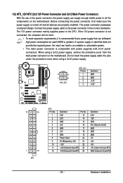
Connect the power supply cable to the CPU. When using a 2x10 power supply. 3 4 1 2 ATX_12V ATX_12V : Pin No. 1 2 3 4 Definition GND GND +12V +12V 12 24 1 13 ATX ATX : Pin No. 1 2 3 4 5 6 7 8 9 10 11 12 Definition ...
Connect the power supply cable to the CPU. When using a 2x10 power supply. 3 4 1 2 ATX_12V ATX_12V : Pin No. 1 2 3 4 Definition GND GND +12V +12V 12 24 1 13 ATX ATX : Pin No. 1 2 3 4 5 6 7 8 9 10 11 12 Definition ...
Manual
Page 24
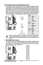
The motherboard supports CPU fan speed control, which requires the use of different color. 34 33 GA-EP35-DS3R/DS3 Motherboard 2 1 - 24 - Most fans are designed with fan speed control design. CPU_FAN: Pin No. Do not place a jumper cap on the ... system fan header (SYS_FAN2) and a 3-pin power fan header (PWR_FAN). The pin 1 of the cable is recommended that a system fan be sure to prevent your CPU and system from overheating. Definition 1 CPU_FAN 1 GND 2 +12V 3 Sense 4 Speed Control 1 SYS_FAN2 SYS_FAN2: Pin No. 1 2 3 4 Definition GND Speed Control Sense +5V 1...
The motherboard supports CPU fan speed control, which requires the use of different color. 34 33 GA-EP35-DS3R/DS3 Motherboard 2 1 - 24 - Most fans are designed with fan speed control design. CPU_FAN: Pin No. Do not place a jumper cap on the ... system fan header (SYS_FAN2) and a 3-pin power fan header (PWR_FAN). The pin 1 of the cable is recommended that a system fan be sure to prevent your CPU and system from overheating. Definition 1 CPU_FAN 1 GND 2 +12V 3 Sense 4 Speed Control 1 SYS_FAN2 SYS_FAN2: Pin No. 1 2 3 4 Definition GND Speed Control Sense +5V 1...
Manual
Page 33
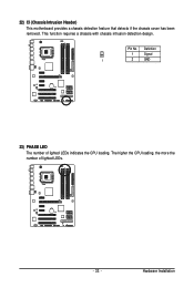
22) CI (Chassis Intrusion Header) This motherboard provides a chassis detection feature that detects if the chassis cover has been removed. Definition 1 Signal 1 2 GND 23) PHASE LED The number of lighted LEDs. - 33 - Hardware Installation This function requires a chassis with chassis intrusion detection design. The higher the CPU loading, the more the number of lighted LEDs indicates the CPU loading. Pin No.
22) CI (Chassis Intrusion Header) This motherboard provides a chassis detection feature that detects if the chassis cover has been removed. Definition 1 Signal 1 2 GND 23) PHASE LED The number of lighted LEDs. - 33 - Hardware Installation This function requires a chassis with chassis intrusion detection design. The higher the CPU loading, the more the number of lighted LEDs indicates the CPU loading. Pin No.
Manual
Page 38
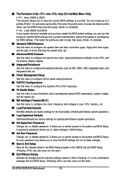
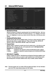
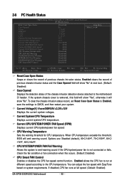
...stop the system boot, etc. „ Advanced BIOS Features Use this menu to configure the device boot order, advanced features available on the CPU, and the primary display adapter. „ Integrated Peripherals Use this menu to configure all peripheral devices, such as IDE, SATA, USB, ... have loaded the BIOS default settings, you can also carry out this menu to see information about autodetected system/CPU temperature, system voltage and fan speed, etc. „ MB Intelligent Tweaker(M.I.T.) Use this task.) GA-EP35-DS3R/DS3 Motherboard - 38 - A supervisor password allows you to a profile.
...stop the system boot, etc. „ Advanced BIOS Features Use this menu to configure the device boot order, advanced features available on the CPU, and the primary display adapter. „ Integrated Peripherals Use this menu to configure all peripheral devices, such as IDE, SATA, USB, ... have loaded the BIOS default settings, you can also carry out this menu to see information about autodetected system/CPU temperature, system voltage and fan speed, etc. „ MB Intelligent Tweaker(M.I.T.) Use this task.) GA-EP35-DS3R/DS3 Motherboard - 38 - A supervisor password allows you to a profile.
Manual
Page 41
to 3 (Note) No-Execute Memory Protect (Note) CPU Enhanced Halt (C1E) (Note) CPU Thermal Monitor 2(TM2) (Note) CPU EIST Function (Note) Virtualization Technology (Note) Full Screen LOGO Show Init Display First [Disabled] [Disabled] [Enabled] [Enabled] [Enabled] [Enabled] [Enabled] [Enabled] [... for entering the BIOS Setup program. (Default) System A password is required every time the system boots, or only when you install a CPU that supports this feature. BIOS Setup First/Second/Third Boot Device Specifies the boot order from the installed hard drives. Capability Enables or disables...
to 3 (Note) No-Execute Memory Protect (Note) CPU Enhanced Halt (C1E) (Note) CPU Thermal Monitor 2(TM2) (Note) CPU EIST Function (Note) Virtualization Technology (Note) Full Screen LOGO Show Init Display First [Disabled] [Disabled] [Enabled] [Enabled] [Enabled] [Enabled] [Enabled] [Enabled] [... for entering the BIOS Setup program. (Default) System A password is required every time the system boots, or only when you install a CPU that supports this feature. BIOS Setup First/Second/Third Boot Device Specifies the boot order from the installed hard drives. Capability Enables or disables...

Manual
Page 42
... Intel's website. set this item to display the GIGABYTE Logo at system startup. This function may enhance protection for the computer, reducing exposure to limit CPUID maximum value. When enabled, the CPU core frequency and voltage will be reduced during system ...Technology (Note) Enables or disables Intel® Virtualization Technology. Set this feature. GA-EP35-DS3R/DS3 Motherboard - 42 - Virtualization enhanced by Intel® Virtualization Technology will be reduced when the CPU is present only if you to determine whether to viruses and malicious buffer overflow ...
... Intel's website. set this item to display the GIGABYTE Logo at system startup. This function may enhance protection for the computer, reducing exposure to limit CPUID maximum value. When enabled, the CPU core frequency and voltage will be reduced during system ...Technology (Note) Enables or disables Intel® Virtualization Technology. Set this feature. GA-EP35-DS3R/DS3 Motherboard - 42 - Virtualization enhanced by Intel® Virtualization Technology will be reduced when the CPU is present only if you to determine whether to viruses and malicious buffer overflow ...
Manual
Page 50
... chassis intrusion status record, set Reset Case Open Status to Enabled, save the settings to run at full speed. (Default: Enabled) GA-EP35-DS3R/DS3 Motherboard - 50 - Current System/CPU Temperature Displays current system/CPU temperature. Options are: Disabled (default), 60oC/140oF, 70oC/158oF, 80oC/ 176oF, 90oC/194oF. You can adjust the fan speed with...
... chassis intrusion status record, set Reset Case Open Status to Enabled, save the settings to run at full speed. (Default: Enabled) GA-EP35-DS3R/DS3 Motherboard - 50 - Current System/CPU Temperature Displays current system/CPU temperature. Options are: Disabled (default), 60oC/140oF, 70oC/158oF, 80oC/ 176oF, 90oC/194oF. You can adjust the fan speed with...
Manual
Page 51
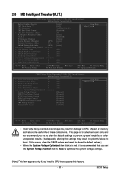
... Tweaker(M.I.T.) CMOS Setup Utility-Copyright (C) 1984-2007 Award Software MB Intelligent Tweaker(M.I.T.) Robust Graphics Booster CPU Clock Ratio (Note) CPU Frequency CPU Host Clock Control x CPU Host Frequency (Mhz) PCI Express Frequency (Mhz) C.I.A. 2 Performance Enhance System Memory Multiplier (SPD... ******** System Voltage Optimized System Voltage Control DDR2 OverVoltage Control PCI-E OverVoltage Control FSB OverVoltage Control (G)MCH OverVoltage Control CPU Voltage Control Normal CPU Vcore 4 28 2 6 3 ******** Auto Auto Auto Auto Auto [Manual] [Normal] [Normal] [Normal] ...
... Tweaker(M.I.T.) CMOS Setup Utility-Copyright (C) 1984-2007 Award Software MB Intelligent Tweaker(M.I.T.) Robust Graphics Booster CPU Clock Ratio (Note) CPU Frequency CPU Host Clock Control x CPU Host Frequency (Mhz) PCI Express Frequency (Mhz) C.I.A. 2 Performance Enhance System Memory Multiplier (SPD... ******** System Voltage Optimized System Voltage Control DDR2 OverVoltage Control PCI-E OverVoltage Control FSB OverVoltage Control (G)MCH OverVoltage Control CPU Voltage Control Normal CPU Vcore 4 28 2 6 3 ******** Auto Auto Auto Auto Auto [Manual] [Normal] [Normal] [Normal] ...

Manual
Page 52
... verify the overclocking capability of your system fails to be changed dynamically based on CPU loading through the use of 5 preset states. Full Thrust Increases CPU frequency by 9% or 11% depending on CPU loading. GA-EP35-DS3R/DS3 Motherboard - 52 - mode based on CPU loading. The adjustable range is from 100 MHz to 266 MHz. Racing Increases...
... verify the overclocking capability of your system fails to be changed dynamically based on CPU loading through the use of 5 preset states. Full Thrust Increases CPU frequency by 9% or 11% depending on CPU loading. GA-EP35-DS3R/DS3 Motherboard - 52 - mode based on CPU loading. The adjustable range is from 100 MHz to 266 MHz. Racing Increases...
Manual
Page 53
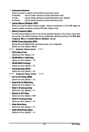
Options are: Auto (default), Manual. ******** Standard Timing Control ******** CAS Latency Time Options are dependent on CPU FSB. Lets the system operate at its good performance level. (Default) Extreme Lets the system operate at its basic performance ... multiplier according to memory SPD data. (Default: Auto) Memory Frequency (Mhz) The first memory frequency value is automatically adjusted according to the CPU Host Frequency (Mhz) and System Memory Multiplier settings. Static tRead Phase Adjust Options are : Auto (default), 1~31. BIOS Setup Performance Enhance...
Options are: Auto (default), Manual. ******** Standard Timing Control ******** CAS Latency Time Options are dependent on CPU FSB. Lets the system operate at its good performance level. (Default) Extreme Lets the system operate at its basic performance ... multiplier according to memory SPD data. (Default: Auto) Memory Frequency (Mhz) The first memory frequency value is automatically adjusted according to the CPU Host Frequency (Mhz) and System Memory Multiplier settings. Static tRead Phase Adjust Options are : Auto (default), 1~31. BIOS Setup Performance Enhance...


