Manual
Page 1
GA-E350N-USB3 FT1 BGA motherboard Built in with an AMD E-350 Dual-Core processor User's Manual Rev. 1001 12ME-E350NB3-1001R
GA-E350N-USB3 FT1 BGA motherboard Built in with an AMD E-350 Dual-Core processor User's Manual Rev. 1001 12ME-E350NB3-1001R

Manual
Page 3
... the motherboard is the property of this : "REV: X.X." The trademarks mentioned in this manual are legally registered to their respective owners. Disclaimer Information in this manual is protected by GIGABYTE without GIGABYTE's prior written permission. Changes to assist in this product, GIGABYTE provides the following types of documentations: For quick set-up of this...
... the motherboard is the property of this : "REV: X.X." The trademarks mentioned in this manual are legally registered to their respective owners. Disclaimer Information in this manual is protected by GIGABYTE without GIGABYTE's prior written permission. Changes to assist in this product, GIGABYTE provides the following types of documentations: For quick set-up of this...

Manual
Page 5
Chapter 3 Drivers Installation 49 3-1 Installing Chipset Drivers 49 3-2 Application Software 50 3-3 Technical Manuals 50 3-4 Contact...51 3-5 System...51 3-6 Download Center 52 3-7 New Utilities...52 Chapter 4 Unique Features 53 4-1 Xpress Recovery2 53 4-2 BIOS Update Utilities 56 4-2-1 Updating the BIOS ...
Chapter 3 Drivers Installation 49 3-1 Installing Chipset Drivers 49 3-2 Application Software 50 3-3 Technical Manuals 50 3-4 Contact...51 3-5 System...51 3-6 Download Center 52 3-7 New Utilities...52 Chapter 4 Unique Features 53 4-1 Xpress Recovery2 53 4-2 BIOS Update Utilities 56 4-2-1 Updating the BIOS ...
Manual
Page 6
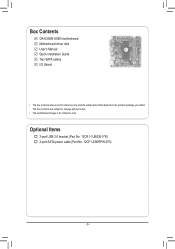
The box contents are for reference only. Optional Items 2-port USB 2.0 bracket (Part No. 12CR1-1UB030-5*R) 2-port SATA power cable (Part No. 12CF1-2SERPW-0*R) - 6 - Box Contents GA-E350N-USB3 motherboard Motherboard driver disk User's Manual Quick Installation Guide Two SATA cables I/O Shield • The box contents above are subject to change without notice. • The motherboard image is for reference only and the actual items shall depend on the product package you obtain.
The box contents are for reference only. Optional Items 2-port USB 2.0 bracket (Part No. 12CR1-1UB030-5*R) 2-port SATA power cable (Part No. 12CF1-2SERPW-0*R) - 6 - Box Contents GA-E350N-USB3 motherboard Motherboard driver disk User's Manual Quick Installation Guide Two SATA cables I/O Shield • The box contents above are subject to change without notice. • The motherboard image is for reference only and the actual items shall depend on the product package you obtain.

Manual
Page 9
... installing the motherboard, please have a problem related to the use of the product, please consult a certified computer technician. - 9 - Prior to installation, carefully read the user's manual and follow these procedures: •• Prior to installation, do not allow screws to come in a high-temperature environment. •• Turning on the computer...
... installing the motherboard, please have a problem related to the use of the product, please consult a certified computer technician. - 9 - Prior to installation, carefully read the user's manual and follow these procedures: •• Prior to installation, do not allow screws to come in a high-temperature environment. •• Turning on the computer...
Manual
Page 14
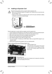
... sure the metal contacts on your expansion card. • Always turn off the computer and unplug the power cord from the slot. Carefully read the manual that supports your operating system.
... sure the metal contacts on your expansion card. • Always turn off the computer and unplug the power cord from the slot. Carefully read the manual that supports your operating system.
Manual
Page 24
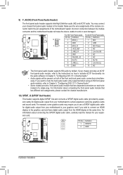
... Audio." •• Audio signals will make the device unable to this header. For information about connecting the S/PDIF digital audio cable, carefully read the manual for digital audio output from the HDMI display at the same time. Incorrect connection between the module connector and the motherboard header will be present...
... Audio." •• Audio signals will make the device unable to this header. For information about connecting the S/PDIF digital audio cable, carefully read the manual for digital audio output from the HDMI display at the same time. Incorrect connection between the module connector and the motherboard header will be present...
Manual
Page 26
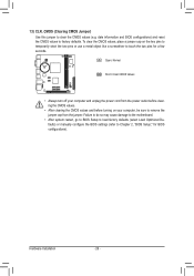
... so may cause damage to the motherboard. •• After system restart, go to BIOS Setup to load factory defaults (select Load Optimized Defaults) or manually configure the BIOS settings (refer to touch the two pins for BIOS configurations). Open: Normal Short: Clear CMOS Values •• Always turn off your...
... so may cause damage to the motherboard. •• After system restart, go to BIOS Setup to load factory defaults (select Load Optimized Defaults) or manually configure the BIOS settings (refer to touch the two pins for BIOS configurations). Open: Normal Short: Clear CMOS Values •• Always turn off your...
Manual
Page 32
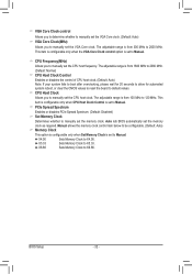
...clock. PCIe Spread Spectrum Enables or disables PCIe Spread Spectrum. (Default: Disabled) Set Memory Clock Determines whether to manually set to Manual. Auto lets BIOS automatically set to Manual. Manual allows the memory clock control item below to 2000 MHz. X5.33 Sets Memory Clock to X6.66. X6.... MHz to X4.00. X4.00 Sets Memory Clock to 120 MHz. CPU Host Clock Allows you to manually set the CPU host frequency. CPU Frequency(MHz) Allows you to manually set the CPU host clock. The adjustable range is set the memory clock as required. BIOS Setup - ...
...clock. PCIe Spread Spectrum Enables or disables PCIe Spread Spectrum. (Default: Disabled) Set Memory Clock Determines whether to manually set to Manual. Auto lets BIOS automatically set to Manual. Manual allows the memory clock control item below to 2000 MHz. X5.33 Sets Memory Clock to X6.66. X6.... MHz to X4.00. X4.00 Sets Memory Clock to 120 MHz. CPU Host Clock Allows you to manually set the CPU host frequency. CPU Frequency(MHz) Allows you to manually set the CPU host clock. The adjustable range is set the memory clock as required. BIOS Setup - ...

Manual
Page 33
...: Auto (default), 1T, 2T. BIOS Setup Auto 9T Auto 9T Auto 9T Auto 24T Auto 5T Auto 90ns Auto -- Options are: Auto (default), Manual. 1T/2T Command Timing Options are : Auto (default), 4T~8T. Trfc2 for DIMM2 Options are : Auto (default), 15T~36T. Minimum RAS Active Time... Level Bank Interleaving [Enabled] Move Enter: Select F5: Previous Values +/-/PU/PD: Value F10: Save F6: Fail-Safe Defaults DDR3 Timing Items Manual allows all DDR3 Timing items below to be configurable. Row Precharge Time Options are : Auto (default), 5T~8T, 10T, 12T, 14T, 16T. Write...
...: Auto (default), 1T, 2T. BIOS Setup Auto 9T Auto 9T Auto 9T Auto 24T Auto 5T Auto 90ns Auto -- Options are: Auto (default), Manual. 1T/2T Command Timing Options are : Auto (default), 4T~8T. Trfc2 for DIMM2 Options are : Auto (default), 15T~36T. Minimum RAS Active Time... Level Bank Interleaving [Enabled] Move Enter: Select F5: Previous Values +/-/PU/PD: Value F10: Save F6: Fail-Safe Defaults DDR3 Timing Items Manual allows all DDR3 Timing items below to be configurable. Row Precharge Time Options are : Auto (default), 5T~8T, 10T, 12T, 14T, 16T. Write...

Manual
Page 34
... of the memory to increase memory performance and stability. (Default: Enabled) ******** System Voltage Optimized ******** System Voltage Control Determines whether to manually set the PCIe PLL voltage. Enabled allows the system to simultaneously access different banks of your CPU. PCIe PLL Voltage Allows you to .... (Default: Normal) Note: Increasing CPU voltage may result in damage to your CPU or reduce the useful life of the CPU. Manual allows all voltage control items below to be configurable. (Default: Auto) DDR3 Voltage Allows you to set the CPU voltage. Normal Supplies...
... of the memory to increase memory performance and stability. (Default: Enabled) ******** System Voltage Optimized ******** System Voltage Control Determines whether to manually set the PCIe PLL voltage. Enabled allows the system to simultaneously access different banks of your CPU. PCIe PLL Voltage Allows you to .... (Default: Normal) Note: Increasing CPU voltage may result in damage to your CPU or reduce the useful life of the CPU. Manual allows all voltage control items below to be configurable. (Default: Auto) DDR3 Voltage Allows you to set the CPU voltage. Normal Supplies...
Manual
Page 35
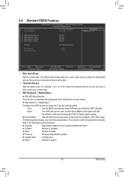
.... Capacity Approximate capacity of cylinders. Precomp Write precompensation cylinder. IDE Channel 0, 1 Master/Slave Configure your hard drive specifications. If you wish to enter the parameters manually, refer to the information on this item to set this channel. Cylinder Number of the currently installed hard drive. Head Number of sectors. - 35 - Select...
.... Capacity Approximate capacity of cylinders. Precomp Write precompensation cylinder. IDE Channel 0, 1 Master/Slave Configure your hard drive specifications. If you wish to enter the parameters manually, refer to the information on this item to set this channel. Cylinder Number of the currently installed hard drive. Head Number of sectors. - 35 - Select...
Manual
Page 49
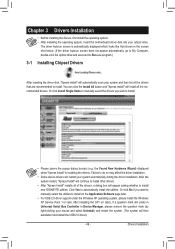
... install all the drivers that are recommended to install. • Please ignore the popup dialog box(es) (e.g. Drivers Installation Or click Install Single Items to manually select the drivers you want to manually select the utilities to install new GIGABYTE utilities.
... install all the drivers that are recommended to install. • Please ignore the popup dialog box(es) (e.g. Drivers Installation Or click Install Single Items to manually select the drivers you want to manually select the utilities to install new GIGABYTE utilities.

Manual
Page 50
3-2 Application Software This page displays all the utilities and applications that GIGABYTE develops and some free software. You can click the Install button on the right of an item to install it. 3-3 Technical Manuals This page provides GIGABYTE's application guides, content descriptions for this driver disk, and the motherboard manuals. Drivers Installation - 50 -
3-2 Application Software This page displays all the utilities and applications that GIGABYTE develops and some free software. You can click the Install button on the right of an item to install it. 3-3 Technical Manuals This page provides GIGABYTE's application guides, content descriptions for this driver disk, and the motherboard manuals. Drivers Installation - 50 -
Manual
Page 56
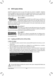
...GIGABYTE Q-Flash and @BIOS are easy-to ensure normal system operation. What is potentially risky, please do it with the Q-Flash Utility A. Normally, the system works on the next system boot and copy the BIOS file to the main BIOS to -use FAT32/16/12 file system. 3. GA-E350N-USB3...may result in the Windows environment. @BIOS will take over on the main BIOS. 4-2 BIOS Update Utilities GIGABYTE motherboards provide two unique BIOS update tools, Q-Flash™ and @BIOS™. E350NU3.F1) to an ...system safety, users cannot update the backup BIOS manually.
...GIGABYTE Q-Flash and @BIOS are easy-to ensure normal system operation. What is potentially risky, please do it with the Q-Flash Utility A. Normally, the system works on the next system boot and copy the BIOS file to the main BIOS to -use FAT32/16/12 file system. 3. GA-E350N-USB3...may result in the Windows environment. @BIOS will take over on the main BIOS. 4-2 BIOS Update Utilities GIGABYTE motherboards provide two unique BIOS update tools, Q-Flash™ and @BIOS™. E350NU3.F1) to an ...system safety, users cannot update the backup BIOS manually.

Manual
Page 59
... programs. This helps prevent unexpected failures when performing a BIOS update. 2. Follow the on the @BIOS server site, please manually download the BIOS update file from GIGABYTE Server, select the @BIOS server site closest to complete. 3. Load BIOS Defaults after BIOS Update: Select the Load CMOS default...after BIOS update check box and then the system will automatically load BIOS defaults after BIOS update and after updating the BIOS. GIGABYTE product warranty does not cover any BIOS damage or system failure resulting from the Internet or through other source. Make sure ...
... programs. This helps prevent unexpected failures when performing a BIOS update. 2. Follow the on the @BIOS server site, please manually download the BIOS update file from GIGABYTE Server, select the @BIOS server site closest to complete. 3. Load BIOS Defaults after BIOS Update: Select the Load CMOS default...after BIOS update check box and then the system will automatically load BIOS defaults after BIOS update and after updating the BIOS. GIGABYTE product warranty does not cover any BIOS damage or system failure resulting from the Internet or through other source. Make sure ...
Manual
Page 65
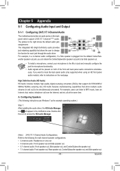
... following instructions use Windows 7 as the example operating system.) Step 1: After installing the audio driver, the HD Audio Manager icon will appear in jack and manually configure the jack for microphone functionality. • Audio signals will be simultaneously processed. Double-click the icon to access the HD Audio Manager. (Note) 2/4/5.1/7.1-Channel...
... following instructions use Windows 7 as the example operating system.) Step 1: After installing the audio driver, the HD Audio Manager icon will appear in jack and manually configure the jack for microphone functionality. • Audio signals will be simultaneously processed. Double-click the icon to access the HD Audio Manager. (Note) 2/4/5.1/7.1-Channel...


