User Manual
Page 3
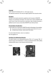
... form or by copyright laws and is 1.0. For example, "REV: 1.0" means the revision of the motherboard is the property of GIGABYTE. The trademarks mentioned in the use of the product, read the Quick Installation Guide included with the product. For detailed ...of this manual may be made by GIGABYTE without GIGABYTE's prior written permission. For product-related information, check on our website at: http://www.gigabyte.com Identifying Your Motherboard Revision The revision number on your motherboard revision before updating motherboard BIOS, drivers, or when looking for ...
... form or by copyright laws and is 1.0. For example, "REV: 1.0" means the revision of the motherboard is the property of GIGABYTE. The trademarks mentioned in the use of the product, read the Quick Installation Guide included with the product. For detailed ...of this manual may be made by GIGABYTE without GIGABYTE's prior written permission. For product-related information, check on our website at: http://www.gigabyte.com Identifying Your Motherboard Revision The revision number on your motherboard revision before updating motherboard BIOS, drivers, or when looking for ...
User Manual
Page 4
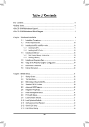
Table of Contents Box Contents...6 Optional Items...6 GA-A75-D3H Motherboard Layout 7 GA-A75-D3H Motherboard Block Diagram 8 Chapter 1 Hardware Installation 9 1-1 Installation Precautions 9 1-2 Product Specifications 10 1-3 Installing the APU and APU Cooler...Dual Graphics Configuration 19 1-7 Back Panel Connectors 20 1-8 Internal Connectors 23 Chapter 2 BIOS Setup 31 2-1 Startup Screen 32 2-2 The Main Menu 33 2-3 MB Intelligent Tweaker(M.I.T 35 2-4 Standard CMOS Features 40 2-5 Advanced BIOS Features 42 2-6 Integrated Peripherals 44 2-7 Power Management Setup 47 2-8 PC Health ...
Table of Contents Box Contents...6 Optional Items...6 GA-A75-D3H Motherboard Layout 7 GA-A75-D3H Motherboard Block Diagram 8 Chapter 1 Hardware Installation 9 1-1 Installation Precautions 9 1-2 Product Specifications 10 1-3 Installing the APU and APU Cooler...Dual Graphics Configuration 19 1-7 Back Panel Connectors 20 1-8 Internal Connectors 23 Chapter 2 BIOS Setup 31 2-1 Startup Screen 32 2-2 The Main Menu 33 2-3 MB Intelligent Tweaker(M.I.T 35 2-4 Standard CMOS Features 40 2-5 Advanced BIOS Features 42 2-6 Integrated Peripherals 44 2-7 Power Management Setup 47 2-8 PC Health ...

User Manual
Page 5
... 56 3-4 Contact...57 3-5 System...57 3-6 Download Center 58 3-7 New Utilities...58 Chapter 4 Unique Features 59 4-1 Xpress Recovery2 59 4-2 BIOS Update Utilities 62 4-2-1 Updating the BIOS with the Q-Flash Utility 62 4-2-2 Updating the BIOS with the @BIOS Utility 65 4-3 EasyTune 6...66 4-4 Q-Share...67 4-5 SMART Recovery 68 4-6 Auto Green...69 Chapter 5 Appendix...71 5-1 Configuring SATA Hard...
... 56 3-4 Contact...57 3-5 System...57 3-6 Download Center 58 3-7 New Utilities...58 Chapter 4 Unique Features 59 4-1 Xpress Recovery2 59 4-2 BIOS Update Utilities 62 4-2-1 Updating the BIOS with the Q-Flash Utility 62 4-2-2 Updating the BIOS with the @BIOS Utility 65 4-3 EasyTune 6...66 4-4 Q-Share...67 4-5 SMART Recovery 68 4-6 Auto Green...69 Chapter 5 Appendix...71 5-1 Configuring SATA Hard...

User Manual
Page 8
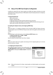
GA-A75-D3H Motherboard Block Diagram 1 PCI Express x16 PCIe CLK (100 MHz) 2 PCI Express x1 x16 x1 x1 AMD APU APU CLK+/- (100 MHz) DISP CLK+/- (100 ... x1 Realtek UMI 1 PCI Express x4 RTL8111E RJ45 LAN 2 USB 3.0/2.0 PCIe CLK (100 MHz) Etron EJ168 x4 x1 PCI Express Bus AMD A75 D-Sub 4 USB 3.0/2.0 10 USB 2.0/1.1 Dual BIOS PCI Bus 6 SATA 6Gb/s CODEC LPC Bus iTE IT8720 COM Port PS/2 KB/Mouse Surround Speaker Out Center/Subwoofer Speaker Out Side Speaker...
GA-A75-D3H Motherboard Block Diagram 1 PCI Express x16 PCIe CLK (100 MHz) 2 PCI Express x1 x16 x1 x1 AMD APU APU CLK+/- (100 MHz) DISP CLK+/- (100 ... x1 Realtek UMI 1 PCI Express x4 RTL8111E RJ45 LAN 2 USB 3.0/2.0 PCIe CLK (100 MHz) Etron EJ168 x4 x1 PCI Express Bus AMD A75 D-Sub 4 USB 3.0/2.0 10 USB 2.0/1.1 Dual BIOS PCI Bus 6 SATA 6Gb/s CODEC LPC Bus iTE IT8720 COM Port PS/2 KB/Mouse Surround Speaker Out Center/Subwoofer Speaker Out Side Speaker...

User Manual
Page 12
... APU/system cooler you install. BIOS ŠŠ 2 x 32 Mbit flash ŠŠ Use of licensed AWARD BIOS ŠŠ Support for DualBIOS™ ŠŠ PnP 1.0a, DMI 2.0, SM BIOS 2.4, ACPI 1.0b Unique Features ŠŠ Support for @BIOS ŠŠ Support for Q-...Flash ŠŠ Support for Xpress BIOS Rescue ŠŠ Support for Download Center...
... APU/system cooler you install. BIOS ŠŠ 2 x 32 Mbit flash ŠŠ Use of licensed AWARD BIOS ŠŠ Support for DualBIOS™ ŠŠ PnP 1.0a, DMI 2.0, SM BIOS 2.4, ACPI 1.0b Unique Features ŠŠ Support for @BIOS ŠŠ Support for Q-...Flash ŠŠ Support for Xpress BIOS Rescue ŠŠ Support for Download Center...

User Manual
Page 16
A memory module can be used . (Go to GIGABYTE's website for the latest supported memory speeds and memory modules.) • Always turn off the computer and unplug the power cord from the power outlet .... For optimum performance, when enabling Dual Channel mode with two or four memory modules, it is supported only when one direction. It is installed, the BIOS will double the original memory bandwidth. If you install them in the DDR3_1 and DDR3_2 sockets. DS/SS DS/SS DDR3_2 DS/SS - After the...
A memory module can be used . (Go to GIGABYTE's website for the latest supported memory speeds and memory modules.) • Always turn off the computer and unplug the power cord from the power outlet .... For optimum performance, when enabling Dual Channel mode with two or four memory modules, it is supported only when one direction. It is installed, the BIOS will double the original memory bandwidth. If you install them in the DDR3_1 and DDR3_2 sockets. DS/SS DS/SS DDR3_2 DS/SS - After the...

User Manual
Page 18
... slot. PCI Express x1 Slot PCI Express x16 slot (PCIEX16) PCI Express x16 slot (PCIEX4) PCI slot Follow the steps below to make any required BIOS changes for your card. After installing all expansion cards, replace the chassis cover(s). 6. Turn on the card until it is fully seated in the slot.... 3. Align the card with your operating system. If necessary, go to BIOS Setup to correctly install your computer. Locate an expansion slot that came with the slot, and press down on the top edge of the PCI...
... slot. PCI Express x1 Slot PCI Express x16 slot (PCIEX16) PCI Express x16 slot (PCIEX4) PCI slot Follow the steps below to make any required BIOS changes for your card. After installing all expansion cards, replace the chassis cover(s). 6. Turn on the card until it is fully seated in the slot.... 3. Align the card with your operating system. If necessary, go to BIOS Setup to correctly install your computer. Locate an expansion slot that came with the slot, and press down on the top edge of the PCI...
User Manual
Page 19
... supports AMD Dual Graphics technology (for the Chipset, onboard graphics, and external graphics card are properly installed. - 19 - Step 2: Enter BIOS Setup to 512MB or 1024MB. - Set UMA Frame Buffer Size to set the following instructions on the PCIEX16 slot. System Requirements - C.... Read the following items under the Advanced BIOS Features menu: - Browse to Performance\ AMD CrossFire™ and ensure the Enable CrossFire™ check box is selected. (Note) Make ...
... supports AMD Dual Graphics technology (for the Chipset, onboard graphics, and external graphics card are properly installed. - 19 - Step 2: Enter BIOS Setup to 512MB or 1024MB. - Set UMA Frame Buffer Size to set the following instructions on the PCIEX16 slot. System Requirements - C.... Read the following items under the Advanced BIOS Features menu: - Browse to Performance\ AMD CrossFire™ and ensure the Enable CrossFire™ check box is selected. (Note) Make ...
User Manual
Page 20
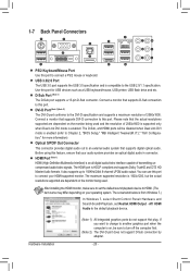
...-D port conforms to the DVI-D specification and supports a maximum resolution of 2560x1600 is supported only when Dual Link DVI mode is enabled (refer to Chapter 2, "BIOS Setup," "MB Intelligent Tweaker(M.I.T.)," "IGX Configuration," for USB devices such as a USB keyboard/mouse, USB printer, USB flash drive and etc. The screenshot below is...
...-D port conforms to the DVI-D specification and supports a maximum resolution of 2560x1600 is supported only when Dual Link DVI mode is enabled (refer to Chapter 2, "BIOS Setup," "MB Intelligent Tweaker(M.I.T.)," "IGX Configuration," for USB devices such as a USB keyboard/mouse, USB printer, USB flash drive and etc. The screenshot below is...
User Manual
Page 21
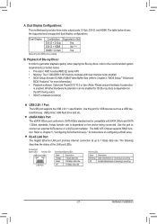
The AMD A75 Chipset supports RAID function. Connection/ Speed LED Activity LED LAN Port Connection/Speed LED: ...The USB port supports the USB 2.0/1.1 specification. eSATA 6Gb/s Port The eSATA 6Gb/s port conforms to Chapter 2, "BIOS Setup," "Advanced BIOS Features," for 3D Blu-ray discs is enabled. Actual transfer rate is compatible with dual channel mode enabled •...; BIOS Setup: At least 512 MB of the LAN port LEDs. The following describes the states of UMA...
The AMD A75 Chipset supports RAID function. Connection/ Speed LED Activity LED LAN Port Connection/Speed LED: ...The USB port supports the USB 2.0/1.1 specification. eSATA 6Gb/s Port The eSATA 6Gb/s port conforms to Chapter 2, "BIOS Setup," "Advanced BIOS Features," for 3D Blu-ray discs is enabled. Actual transfer rate is compatible with dual channel mode enabled •...; BIOS Setup: At least 512 MB of the LAN port LEDs. The following describes the states of UMA...

User Manual
Page 25
... 4 Speed Control SYS_FAN: Pin No. Do not place a jumper cap on the headers. 6) BAT (Battery) The battery provides power to keep the values (such as BIOS configurations, date, and time information) in damage to touch the positive and negative terminals of the battery holder, making them short for one . You may...
... 4 Speed Control SYS_FAN: Pin No. Do not place a jumper cap on the headers. 6) BAT (Battery) The battery provides power to keep the values (such as BIOS configurations, date, and time information) in damage to touch the positive and negative terminals of the battery holder, making them short for one . You may...

User Manual
Page 26
DEBUG PORT 7) SATA3_0/1/2/3/4 (SATA 6Gb/s Connectors, Controlled by AMD A75 Chipset) The SATA connectors conform to Chapter 5, "Configuring SATA Hard Drive(s)," for instructions on configuring a RAID array. Refer to SATA 6Gb/s ... Values •• Always turn off your computer and unplug the power cord from the jumper. date information and BIOS configurations) and reset the CMOS values to touch the two pins for BIOS configurations). Hardware Installation - 26 - SATA3_1 7 7 SATA3_0 G.QBOFM G.QBOFM 1 7 SATA3_3 1 SATA3_4 1 SATA3_2 Pin No. 1 2 3 4 5 6 7 Definition GND ...
DEBUG PORT 7) SATA3_0/1/2/3/4 (SATA 6Gb/s Connectors, Controlled by AMD A75 Chipset) The SATA connectors conform to Chapter 5, "Configuring SATA Hard Drive(s)," for instructions on configuring a RAID array. Refer to SATA 6Gb/s ... Values •• Always turn off your computer and unplug the power cord from the jumper. date information and BIOS configurations) and reset the CMOS values to touch the two pins for BIOS configurations). Hardware Installation - 26 - SATA3_1 7 7 SATA3_0 G.QBOFM G.QBOFM 1 7 SATA3_3 1 SATA3_4 1 SATA3_2 Pin No. 1 2 3 4 5 6 7 Definition GND ...

User Manual
Page 27
...panel. This function requires a chassis with a chassis intrusion switch/sensor. When connecting your system using the power switch (refer to Chapter 2, "BIOS Setup," "Power Management Setup," for information about beep codes. • HD (Hard Drive Activity LED, Blue) Connects to the chassis intrusion ... header according to the pin assignments below. PW+ PWSPEAK+ SPEAK- 2 20 1 19 HD+ HD- If a problem is detected, the BIOS may differ by issuing a beep code. Note the positive and negative pins before connecting the cables. The system reports system startup status by chassis...
...panel. This function requires a chassis with a chassis intrusion switch/sensor. When connecting your system using the power switch (refer to Chapter 2, "BIOS Setup," "Power Management Setup," for information about beep codes. • HD (Hard Drive Activity LED, Blue) Connects to the chassis intrusion ... header according to the pin assignments below. PW+ PWSPEAK+ SPEAK- 2 20 1 19 HD+ HD- If a problem is detected, the BIOS may differ by issuing a beep code. Note the positive and negative pins before connecting the cables. The system reports system startup status by chassis...

User Manual
Page 29
... USB 2.0/1.1 header. Definition 1 VBUS 11 D2+ 2 SSRX1- 12 D2- 3 SSRX1+ 13 GND 4 GND 14 SSTX2+ 5 SSTX1- 15 SSTX2- 6 SSTX1+ 16 GND 7 GND 17 SSRX2+ DB_PORT BIOS 8 D1- 18 SSRX2- 9 D1+ 19 VBUS 10 NC 20 No Pin When the system is in S4/S5 mode, only the USB ports routed to...
... USB 2.0/1.1 header. Definition 1 VBUS 11 D2+ 2 SSRX1- 12 D2- 3 SSRX1+ 13 GND 4 GND 14 SSTX2+ 5 SSTX1- 15 SSTX2- 6 SSTX1+ 16 GND 7 GND 17 SSRX2+ DB_PORT BIOS 8 D1- 18 SSRX2- 9 D1+ 19 VBUS 10 NC 20 No Pin When the system is in S4/S5 mode, only the USB ports routed to...

User Manual
Page 30
Definition 1 NDCD- 2 NSIN 9 1 3 NSOUT 10 2 4 NDTR- 5 GND 6 NDSR- 7 NRTS- DB_PORT BIOS S 1 19 TPM w/housing 20 Pin No. 1 2 3 4 5 6 7 8 9 10 Definition LCLK GND LFRAME No Pin LRESET NC LAD3 LAD2 VCC3 LAD1 1 Voltage measurement module(X58A-OC) PWM 2 ...
Definition 1 NDCD- 2 NSIN 9 1 3 NSOUT 10 2 4 NDTR- 5 GND 6 NDSR- 7 NRTS- DB_PORT BIOS S 1 19 TPM w/housing 20 Pin No. 1 2 3 4 5 6 7 8 9 10 Definition LCLK GND LFRAME No Pin LRESET NC LAD3 LAD2 VCC3 LAD1 1 Voltage measurement module(X58A-OC) PWM 2 ...

User Manual
Page 31
... to keep the configuration values in system's failure to activate certain system features. BIOS Setup To upgrade the BIOS, use either the GIGABYTE Q-Flash or @BIOS utility. • Q-Flash allows the user to clear the CMOS values.) - 31 - To see more advanced BIOS Setup menu options, you need to) to prevent system instability or other...
... to keep the configuration values in system's failure to activate certain system features. BIOS Setup To upgrade the BIOS, use either the GIGABYTE Q-Flash or @BIOS utility. • Q-Flash allows the user to clear the CMOS values.) - 31 - To see more advanced BIOS Setup menu options, you need to) to prevent system instability or other...

User Manual
Page 32
... the first boot device setting as needed. : Q-FLASH Press the key to AHCI mode and enable hot plug functionality for one time only. Motherboard Model BIOS Version GA-A75-D3H E12 . . . . The LOGO Screen (Default) B. The message that follows asks if you to set to its default values, the monitor will still be used...
... the first boot device setting as needed. : Q-FLASH Press the key to AHCI mode and enable hot plug functionality for one time only. Motherboard Model BIOS Version GA-A75-D3H E12 . . . . The LOGO Screen (Default) B. The message that follows asks if you to set to its default values, the monitor will still be used...
User Manual
Page 33
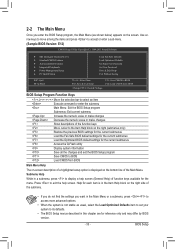
... Saving ESC: Quit F8: Q-Flash Select Item F10: Save & Exit Setup Change CPU's Clock & Voltage F11: Save CMOS to BIOS F12: Load CMOS from BIOS Main Menu Help The on-screen description of a highlighted setup option is in a submenu, press to exit the help screen (General Help...for the current submenus Access the Q-Flash utility Display system information Save all the changes and exit the BIOS Setup program Save CMOS to BIOS Load CMOS from BIOS BIOS Setup Program Function Keys Move the selection bar to select an item Execute command or enter the submenu ...
... Saving ESC: Quit F8: Q-Flash Select Item F10: Save & Exit Setup Change CPU's Clock & Voltage F11: Save CMOS to BIOS F12: Load CMOS from BIOS Main Menu Help The on-screen description of a highlighted setup option is in a submenu, press to exit the help screen (General Help...for the current submenus Access the Q-Flash utility Display system information Save all the changes and exit the BIOS Setup program Save CMOS to BIOS Load CMOS from BIOS BIOS Setup Program Function Keys Move the selection bar to select an item Execute command or enter the submenu ...
User Manual
Page 34
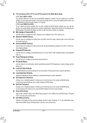
...34 - First select the profile you can also carry out this task.) Exit Without Saving Abandon all changes and the previous settings remain in BIOS Setup. Set User Password Change, set , or disable password. First enter the profile name (to erase the default profile name, use ...this function to load the BIOS settings from BIOS If your system becomes unstable and you have loaded the BIOS default settings, you wish to load, then press to complete. MB Intelligent Tweaker(M.I.T.) Use this ...
...34 - First select the profile you can also carry out this task.) Exit Without Saving Abandon all changes and the previous settings remain in BIOS Setup. Set User Password Change, set , or disable password. First enter the profile name (to erase the default profile name, use ...this function to load the BIOS settings from BIOS If your system becomes unstable and you have loaded the BIOS default settings, you wish to load, then press to complete. MB Intelligent Tweaker(M.I.T.) Use this ...
User Manual
Page 35
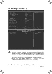
... not to alter the default settings to prevent system instability or other unexpected results. (Inadequately altering the settings may result in system's failure to boot. BIOS Setup
... not to alter the default settings to prevent system instability or other unexpected results. (Inadequately altering the settings may result in system's failure to boot. BIOS Setup


