
User Manual
Page 1
GA-A55M-S2V User's Manual Rev. 1001 12ME-A55M2V-1001R
GA-A55M-S2V User's Manual Rev. 1001 12ME-A55M2V-1001R
User Manual
Page 3
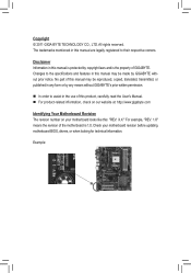
..., "REV: 1.0" means the revision of this product, carefully read the User's Manual. For product-related information, check on our website at: http://www.gigabyte.com Identifying Your Motherboard Revision The revision number on your motherboard revision before updating motherboard...is 1.0. Disclaimer Information in this manual are legally registered to the specifications and features in the use of the motherboard is the property of GIGABYTE. Example: The trademarks mentioned in this manual is protected by GIGABYTE without GIGABYTE's prior written permission. ...
..., "REV: 1.0" means the revision of this product, carefully read the User's Manual. For product-related information, check on our website at: http://www.gigabyte.com Identifying Your Motherboard Revision The revision number on your motherboard revision before updating motherboard...is 1.0. Disclaimer Information in this manual are legally registered to the specifications and features in the use of the motherboard is the property of GIGABYTE. Example: The trademarks mentioned in this manual is protected by GIGABYTE without GIGABYTE's prior written permission. ...
User Manual
Page 5
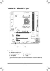
GA-A55M-S2V Motherboard Layout KB_MS VGA ATX_12V CPU_FAN Socket FM1 SYS_FAN ATX DVI R_USB USB_LAN Realtek RTL8111E AUDIO BAT PCIEX16 iTE IT8720 PCIEX1_1 PCI CODEC PCIEX1_2 F_AUDIO SPDIF_O TPM GA-A55M-S2V F_USB1 COM F_USB2 F_PANEL M_BIOS AMD A75/A55 SATA2_0 B_BIOS SATA2_5 SATA2_4 SATA2_3 SATA2_2 SATA2_1 DDR3_2 DDR3_1 CLR_CMOS Box Contents GA-A55M-S2V motherboard Motherboard driver disk User's Manual Two SATA cables I/O Shield * The box contents above are for reference only and the actual items shall depend on the product package you obtain. - 5 -
GA-A55M-S2V Motherboard Layout KB_MS VGA ATX_12V CPU_FAN Socket FM1 SYS_FAN ATX DVI R_USB USB_LAN Realtek RTL8111E AUDIO BAT PCIEX16 iTE IT8720 PCIEX1_1 PCI CODEC PCIEX1_2 F_AUDIO SPDIF_O TPM GA-A55M-S2V F_USB1 COM F_USB2 F_PANEL M_BIOS AMD A75/A55 SATA2_0 B_BIOS SATA2_5 SATA2_4 SATA2_3 SATA2_2 SATA2_1 DDR3_2 DDR3_1 CLR_CMOS Box Contents GA-A55M-S2V motherboard Motherboard driver disk User's Manual Two SATA cables I/O Shield * The box contents above are for reference only and the actual items shall depend on the product package you obtain. - 5 -

User Manual
Page 7
... damaged as a motherboard, APU or memory. ponents such as a result of the product, please consult a certified computer technician. - 7 - Prior to installation, carefully read the user's manual and follow these procedures: •• Prior to the use of electrostatic discharge (ESD).
... damaged as a motherboard, APU or memory. ponents such as a result of the product, please consult a certified computer technician. - 7 - Prior to installation, carefully read the user's manual and follow these procedures: •• Prior to the use of electrostatic discharge (ESD).

User Manual
Page 11
... recommended that memory of the same capacity, brand, speed, and chips be used . (Go to GIGABYTE's website for optimum performance. 1-5 Installing an Expansion Card Read the following guidelines before you begin to APU limitations, read the manual that came with two memory modules, it is installed, the BIOS will double the original...
... recommended that memory of the same capacity, brand, speed, and chips be used . (Go to GIGABYTE's website for optimum performance. 1-5 Installing an Expansion Card Read the following guidelines before you begin to APU limitations, read the manual that came with two memory modules, it is installed, the BIOS will double the original...

User Manual
Page 18
For information about connecting the S/PDIF digital audio cable, carefully read the manual for digital audio output from your motherboard to your graphics card if you to use a S/PDIF digital audio cable for your chassis front panel audio ...
For information about connecting the S/PDIF digital audio cable, carefully read the manual for digital audio output from your motherboard to your graphics card if you to use a S/PDIF digital audio cable for your chassis front panel audio ...
User Manual
Page 20
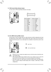
...) You may cause damage to the motherboard. •• After system restart, go to BIOS Setup to load factory defaults (select Load Optimized Defaults) or manually configure the BIOS settings (refer to Chapter 2, "BIOS Setup," for a few seconds. To clear the CMOS values, place a jumper cap on your computer, be sure...
...) You may cause damage to the motherboard. •• After system restart, go to BIOS Setup to load factory defaults (select Load Optimized Defaults) or manually configure the BIOS settings (refer to Chapter 2, "BIOS Setup," for a few seconds. To clear the CMOS values, place a jumper cap on your computer, be sure...

User Manual
Page 24
...your overall system configurations. Options are: Auto (default), 256MB, 512MB, 1024MB. VGA Core Clock control Allows you to determine whether to manually set the VGA Core clock. Incorrectly doing overclock/overvoltage may result in system's failure to 2000 MHz. Core Performance Boost (Note) ... to default values.) • When the System Voltage Optimized item blinks in damage to manually set the VGA Core clock. (Default: Auto) VGA Core Clock(MHz) Allows you set to Manual. (Note) This item is for the onboard graphics controller. 2-3 MB Intelligent Tweaker(M.I.T.) ...
...your overall system configurations. Options are: Auto (default), 256MB, 512MB, 1024MB. VGA Core Clock control Allows you to determine whether to manually set the VGA Core clock. Incorrectly doing overclock/overvoltage may result in system's failure to 2000 MHz. Core Performance Boost (Note) ... to default values.) • When the System Voltage Optimized item blinks in damage to manually set the VGA Core clock. (Default: Auto) VGA Core Clock(MHz) Allows you set to Manual. (Note) This item is for the onboard graphics controller. 2-3 MB Intelligent Tweaker(M.I.T.) ...

User Manual
Page 25
...Memory Clock This option is configurable only when Set Memory Clock is highly recommended that supports this feature. - 25 - Manual allows the CPU Frequency (MHz) item below to Manual. PCIe Spread Spectrum Enables or disables PCIe Spread Spectrum. (Default: Disabled) Set Memory Clock Determines whether to default ... CPU Frequency(MHz) Allows you alter the ratio for automated system reboot, or clear the CMOS values to reset the board to manually set the CPU host frequency.. This option is configurable only when CPU Host Clock Control is dependent on the CPU being installed. ...
...Memory Clock This option is configurable only when Set Memory Clock is highly recommended that supports this feature. - 25 - Manual allows the CPU Frequency (MHz) item below to Manual. PCIe Spread Spectrum Enables or disables PCIe Spread Spectrum. (Default: Disabled) Set Memory Clock Determines whether to default ... CPU Frequency(MHz) Allows you alter the ratio for automated system reboot, or clear the CMOS values to reset the board to manually set the CPU host frequency.. This option is configurable only when CPU Host Clock Control is dependent on the CPU being installed. ...

User Manual
Page 26
... Bank Interleaving [Enabled] Move Enter: Select F5: Previous Values +/-/PU/PD: Value F10: Save F6: Fail-Safe Defaults DDR3 Timing Items Manual allows all DDR3 Timing items below to RAS Delay Options are : Auto (default), 90ns, 110ns, 160ns, 300ns, 350ns. Row Cycle Time Options ... Options are : Auto (default), 1T, 2T. Trfc0 for DIMM2 Options are : Auto (default), 16T~40T. - 26 - Options are: Auto (default), Manual. 1T/2T Command Timing Options are : Auto (default), 5T~14T. ESC: Exit F1: General Help F7: Optimized Defaults Four Bank Activate Window Options are ...
... Bank Interleaving [Enabled] Move Enter: Select F5: Previous Values +/-/PU/PD: Value F10: Save F6: Fail-Safe Defaults DDR3 Timing Items Manual allows all DDR3 Timing items below to RAS Delay Options are : Auto (default), 90ns, 110ns, 160ns, 300ns, 350ns. Row Cycle Time Options ... Options are : Auto (default), 1T, 2T. Trfc0 for DIMM2 Options are : Auto (default), 16T~40T. - 26 - Options are: Auto (default), Manual. 1T/2T Command Timing Options are : Auto (default), 5T~14T. ESC: Exit F1: General Help F7: Optimized Defaults Four Bank Activate Window Options are ...

User Manual
Page 27
... is from -0.600V to set the system voltages as required. (Default) 1.025V ~ 2.135V The adjustable range is from 1.025V to 1.735V. Manual allows all voltage control items below to be configurable. (Default: Auto) DDR3 Voltage Control Allows you to set the CPU NorthBridge VID voltage. CPU ...VDDP Voltage Control Allows you to set the Chipset voltage. FCH Voltage Control Allows you to +0.600V. CPU VCORE Control Allows you to manually set the CPU voltage. Normal Supplies the CPU voltage as required. (Default) -0.600V ~ +0.600V The adjustable range is from -0.600V to...
... is from -0.600V to set the system voltages as required. (Default) 1.025V ~ 2.135V The adjustable range is from 1.025V to 1.735V. Manual allows all voltage control items below to be configurable. (Default: Auto) DDR3 Voltage Control Allows you to set the CPU NorthBridge VID voltage. CPU ...VDDP Voltage Control Allows you to set the Chipset voltage. FCH Voltage Control Allows you to +0.600V. CPU VCORE Control Allows you to manually set the CPU voltage. Normal Supplies the CPU voltage as required. (Default) -0.600V ~ +0.600V The adjustable range is from -0.600V to...

User Manual
Page 38
... SATA port on the motherboard. Installing SATA hard drive(s) in your system and then list all the recommended drivers. Or click Install Single Items to manually select the drivers you use two hard drives with identical model and capacity). The driver Autorun screen is recommended that shown in system BIOS Setup...
... SATA port on the motherboard. Installing SATA hard drive(s) in your system and then list all the recommended drivers. Or click Install Single Items to manually select the drivers you use two hard drives with identical model and capacity). The driver Autorun screen is recommended that shown in system BIOS Setup...


