User Manual
Page 2
... Checklist 4 WARNING 4 Chapter 1 Introduction 5 Features Summary 5 GA-9IVDT Motherboard Layout 7 Chapter 2 Hardware Installation Process 9 Step 1: Install the Central Processing Unit (CPU 10 Step 1-2:CPU Heat Sink Installation 11 Step 2: Install memory modules 13 Step 3: Install expansion cards 16 Step 4: Connect ribbon cables, cabinet wires, and power supply 17 Step 4-1 : I/O Back Panel Introduction 17...
... Checklist 4 WARNING 4 Chapter 1 Introduction 5 Features Summary 5 GA-9IVDT Motherboard Layout 7 Chapter 2 Hardware Installation Process 9 Step 1: Install the Central Processing Unit (CPU 10 Step 1-2:CPU Heat Sink Installation 11 Step 2: Install memory modules 13 Step 3: Install expansion cards 16 Step 4: Connect ribbon cables, cabinet wires, and power supply 17 Step 4-1 : I/O Back Panel Introduction 17...
User Manual
Page 4
... spacers to a metal object, such as the power supply case. 3. Installing the motherboard to SATA HDD Power cable x 2 CD for motherboard driver & utility I/O Shield x1 Serial ATA cable x 4 PATA ( 1 cables) & FDD cable set x 1 GA-9IVDT quick installation guide GA-9IVDT user's manual Retention Module x 2 WARNING! In... any printed circuit write or parts on your hands to a safely grounded object or to the mounting holes. English GA-9IVDTMotherboard Item Checklist The GA-9IVDT motherboard Printer Port (LPT) cable x 1 IDE to the chassis... To protect them against damage from the motherboard ...
... spacers to a metal object, such as the power supply case. 3. Installing the motherboard to SATA HDD Power cable x 2 CD for motherboard driver & utility I/O Shield x1 Serial ATA cable x 4 PATA ( 1 cables) & FDD cable set x 1 GA-9IVDT quick installation guide GA-9IVDT user's manual Retention Module x 2 WARNING! In... any printed circuit write or parts on your hands to a safely grounded object or to the mounting holes. English GA-9IVDTMotherboard Item Checklist The GA-9IVDT motherboard Printer Port (LPT) cable x 1 IDE to the chassis... To protect them against damage from the motherboard ...

User Manual
Page 5
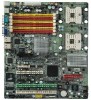
... ZCR) y 1 PCI slot supports 32/33MHz (5V) y 1 PCI-E slot by cable) y 1 x VGA port y 2 x RJ45 LAN port Hardware Monitor y CPU/Power/System Fan Revolution Detect y CPU shutdown when overtemperature y System Voltage Detect 5 y GA-9IVDT Motherboard: CPU Chipset Memory I/O Control Slots On-Board IDE y Dual socket 604 for Intel® Xeon(Nocona/Iwindale) processor suopprts...
... ZCR) y 1 PCI slot supports 32/33MHz (5V) y 1 PCI-E slot by cable) y 1 x VGA port y 2 x RJ45 LAN port Hardware Monitor y CPU/Power/System Fan Revolution Detect y CPU shutdown when overtemperature y System Voltage Detect 5 y GA-9IVDT Motherboard: CPU Chipset Memory I/O Control Slots On-Board IDE y Dual socket 604 for Intel® Xeon(Nocona/Iwindale) processor suopprts...
User Manual
Page 8
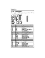
... (System Fan) T. WOL1 (Wake on Ring) C. Intel E7320 3. COM1 (COM Port) H. MV_SATA1 (SATA Connector) 12. USB2 (USB2.0 connector) 13. F_Panel1(Front Panel) 14. PWR_FAN1 (Power Fan) S. ATX2 (Power connector) W. USB1 (USB2.0 port) I. DDR2 O. CPU_FAN1 Q. PCI_E_x4 (PCI-E x4 Slot) ** Note: This device is reserved for Adaptec AIC-8140 chipset. (Supports 8 SATAports) 8 CPU1 (Install...
... (System Fan) T. WOL1 (Wake on Ring) C. Intel E7320 3. COM1 (COM Port) H. MV_SATA1 (SATA Connector) 12. USB2 (USB2.0 connector) 13. F_Panel1(Front Panel) 14. PWR_FAN1 (Power Fan) S. ATX2 (Power connector) W. USB1 (USB2.0 port) I. DDR2 O. CPU_FAN1 Q. PCI_E_x4 (PCI-E x4 Slot) ** Note: This device is reserved for Adaptec AIC-8140 chipset. (Supports 8 SATAports) 8 CPU1 (Install...
User Manual
Page 9
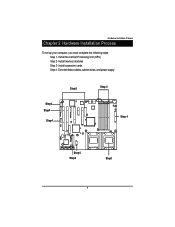
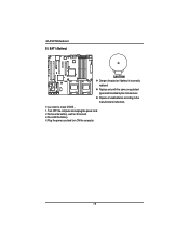
Install memory modules Step 3- Connect ribbon cables, cabinet wires, and power supply Step3 Step 2 Step4 Step4 Step4 㕺㖀㕣 㖅㖃㕲㕢 㕼㖀㖄㕡 㖇㕿㖂㕡 㖇㕿㕼㕡 &#...
Install memory modules Step 3- Connect ribbon cables, cabinet wires, and power supply Step3 Step 2 Step4 Step4 Step4 㕺㖀㕣 㖅㖃㕲㕢 㕼㖀㖄㕡 㖇㕿㖂㕡 㖇㕿㕼㕡 &#...
User Manual
Page 11
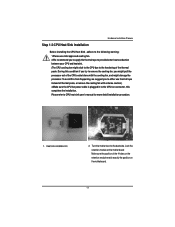
... to the following warning: 1.Please use thermal tape instead of thermal paste, or remove the cooling fan with extreme caution.) 3.Make sure the CPU fan power cable is plugged in to the CPU fan connector, this condition if you try to remove the cooling fan, you to apply the thermal tape...
... to the following warning: 1.Please use thermal tape instead of thermal paste, or remove the cooling fan with extreme caution.) 3.Make sure the CPU fan power cable is plugged in to the CPU fan connector, this condition if you try to remove the cooling fan, you to apply the thermal tape...
User Manual
Page 14
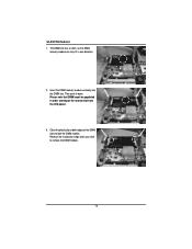
Notch 14 Insert the DIMM memory module vertically into the DIMM slot. English GA-9IVDTMotherboard 1. Close the plastic clip at the nearest slot from the ATX power. 3. The DIMM slot has a notch, so the DIMM memory module can only fit in order starting at both edges of the DIMM slots to remove the DIMM module. Then push it down. Reverse the installation steps when you wish to lock the DIMM module. Please note that DIMM must be populated in one direction. 2.
Notch 14 Insert the DIMM memory module vertically into the DIMM slot. English GA-9IVDTMotherboard 1. Close the plastic clip at the nearest slot from the ATX power. 3. The DIMM slot has a notch, so the DIMM memory module can only fit in order starting at both edges of the DIMM slots to remove the DIMM module. Then push it down. Reverse the installation steps when you wish to lock the DIMM module. Please note that DIMM must be populated in one direction. 2.
User Manual
Page 16
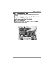
... before install the expansion card into expansion slot in the slot. 5. Replace the screw to secure the slot bracket of expansion card from the computer. 3. Power on the card are indeed seated in motherboard. 4. Replace your server's chassis cover, necessary screws and slot bracket from BIOS. 8. Remove your computer's chassis cover...
... before install the expansion card into expansion slot in the slot. 5. Replace the screw to secure the slot bracket of expansion card from the computer. 3. Power on the card are indeed seated in motherboard. 4. Replace your server's chassis cover, necessary screws and slot bracket from BIOS. 8. Remove your computer's chassis cover...
User Manual
Page 17
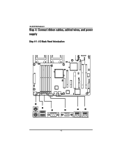
\ \ [ 17 GA-9IVDTMotherboard Step 4: Connect ribbon cables, cabinet wires, and power supply Step 4-1 : I/O Back Panel Introduction 㕺㖀㕣 㖅㖃㕲㕢 㕢 㕹㕴㕵㕡 㖇㕿㕼㕡 㖇㕿㖂㕡 &#...
\ \ [ 17 GA-9IVDTMotherboard Step 4: Connect ribbon cables, cabinet wires, and power supply Step 4-1 : I/O Back Panel Introduction 㕺㖀㕣 㖅㖃㕲㕢 㕢 㕹㕴㕵㕡 㖇㕿㕼㕡 㖇㕿㖂㕡 &#...
User Manual
Page 20
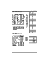
...;㕡 㕼㕧 㕼㕡 㕼㕧 㕼㕡 㕼㕧 㕼㕡 20 A) ATX 1 (ATX Power Connector) 㕳㕿㕽㕡 㖅㖃㕲㕡 㕴㕴㖂㕢 㕼㖀㖄㕡 㕱㖄㖈&#...;㕧 㕼㕡 㕼㕧 㕼㕡 㕼㕧 㕼㕡 AC power cord should only be connected to your power supply unit after ATX power cable and other related devices are firmly connected to the mainboard.
...;㕡 㕼㕧 㕼㕡 㕼㕧 㕼㕡 㕼㕧 㕼㕡 20 A) ATX 1 (ATX Power Connector) 㕳㕿㕽㕡 㖅㖃㕲㕡 㕴㕴㖂㕢 㕼㖀㖄㕡 㕱㖄㖈&#...;㕧 㕼㕡 㕼㕧 㕼㕡 㕼㕧 㕼㕡 AC power cord should only be connected to your power supply unit after ATX power cable and other related devices are firmly connected to the mainboard.
User Manual
Page 23
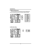
...13693;㕡 㖅㖃㕲㕡 㕱㖄㖈㕡 㕺㖀㕡 12 9 10 Pin No. 1 2 3 4 5 6 7 8 9 10 Definition Power Power USB DxUSB DyUSB Dx+ USB Dy+ GND GND No Pin OC I ) WOR1 (Wake on Ring) 㕼㖀㖄㕡 㖇㕿㖂㕡 㕺㖀... 1 Pin No. 1 2 Definition Signal GND 23 Check the pin assignment while you connect the front USB cable. English GA-9IVDTMotherboard H ) USB2 (Front USB Connector ) Be careful with the polarity of the front USB connector.
...13693;㕡 㖅㖃㕲㕡 㕱㖄㖈㕡 㕺㖀㕡 12 9 10 Pin No. 1 2 3 4 5 6 7 8 9 10 Definition Power Power USB DxUSB DyUSB Dx+ USB Dy+ GND GND No Pin OC I ) WOR1 (Wake on Ring) 㕼㖀㖄㕡 㖇㕿㖂㕡 㕺㖀... 1 Pin No. 1 2 Definition Signal GND 23 Check the pin assignment while you connect the front USB cable. English GA-9IVDTMotherboard H ) USB2 (Front USB Connector ) Be careful with the polarity of the front USB connector.
User Manual
Page 25
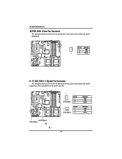
English GA-9IVDTMotherboard M) PWR_FAN1 (Power Fan Connector) This connector allows you to link with the cooling fan on the system case to lower the system temperature. 㕼㖀㖄㕡 &#...
English GA-9IVDTMotherboard M) PWR_FAN1 (Power Fan Connector) This connector allows you to link with the cooling fan on the system case to lower the system temperature. 㕼㖀㖄㕡 &#...
User Manual
Page 27
English GA-9IVDTMotherboard R ) F_Panel1 ( 2 x 12 pins connector) &Please connect the power LED, PC speaker, reset switch and power switch of your chassis front panel to the F_PANEL connector according to the pin assignment above. 㕺&#...HDSYS_STATUSPWB+ LAN1_ACT PWB+ GND L1_LINKRST_BTNSENSOR_SDA RST_BTN_GND SENSOR_SCL SV_SWCASE_OPEN# SV_SW- (GND) LAN2_ACT NMI_SWL2_LINK- Description Dual Color LED (+/-) / Single Color LED (-) P5VStand By Power (Reserverd) Pin Removed ID LED Signal anode (+) Dual Color LED (-/+) / Single Color LED (+) ID LED Signal cathode(-) Hard Disk LED Signal ...
English GA-9IVDTMotherboard R ) F_Panel1 ( 2 x 12 pins connector) &Please connect the power LED, PC speaker, reset switch and power switch of your chassis front panel to the F_PANEL connector according to the pin assignment above. 㕺&#...HDSYS_STATUSPWB+ LAN1_ACT PWB+ GND L1_LINKRST_BTNSENSOR_SDA RST_BTN_GND SENSOR_SCL SV_SWCASE_OPEN# SV_SW- (GND) LAN2_ACT NMI_SWL2_LINK- Description Dual Color LED (+/-) / Single Color LED (-) P5VStand By Power (Reserverd) Pin Removed ID LED Signal anode (+) Dual Color LED (-/+) / Single Color LED (+) ID LED Signal cathode(-) Hard Disk LED Signal ...
User Manual
Page 28
Replace only with the same or equivalent type recommended by the manufacturer. If you want to the manufacturer's instructions. English GA-9IVDTMotherboard S ) BAT1 (Battery) 㕳㕿㕽㕡 㖅㖃㕲㕡 㕴㕴㖂㕢 㕼㖀&#...of used batteries according to erase CMOS... 1.Turn OFF the computer and unplug the power cord. 2.Remove the battery, wait for 30 second. 3.Re-install the battery. 4.Plug the power cord and turn ON the computer. 28 Dispose of explosion if battery is incorrectly replaced...
Replace only with the same or equivalent type recommended by the manufacturer. If you want to the manufacturer's instructions. English GA-9IVDTMotherboard S ) BAT1 (Battery) 㕳㕿㕽㕡 㖅㖃㕲㕡 㕴㕴㖂㕢 㕼㖀&#...of used batteries according to erase CMOS... 1.Turn OFF the computer and unplug the power cord. 2.Remove the battery, wait for 30 second. 3.Re-install the battery. 4.Plug the power cord and turn ON the computer. 28 Dispose of explosion if battery is incorrectly replaced...
User Manual
Page 32
...Reserved Reserved Reserved Load the Optimized Defaults Save all the CMOS changes, only for Main Menu 32 Exit current page and return to enter Setup. GA-9IVDT Motherboard Chapter 3 BIOS Setup BIOS Setup is turned off. CONTROL KEYS Move to previous item Move to next item Move to the item in the... not save changes into CMOS Status Page Setup Menu and Option Page Setup Menu - The program that it retains the Setup information when the power is an overview of information is stored in battery-backed CMOS RAM so that allows users to the item in the left hand Move to...
...Reserved Reserved Reserved Load the Optimized Defaults Save all the CMOS changes, only for Main Menu 32 Exit current page and return to enter Setup. GA-9IVDT Motherboard Chapter 3 BIOS Setup BIOS Setup is turned off. CONTROL KEYS Move to previous item Move to next item Move to the item in the... not save changes into CMOS Status Page Setup Menu and Option Page Setup Menu - The program that it retains the Setup information when the power is an overview of information is stored in battery-backed CMOS RAM so that allows users to the item in the left hand Move to...
User Manual
Page 47
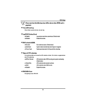
... Enabled Enable Extended Memory Testing. (Default value) Disabled Disable this function. (Default value) System After AC Back Set the mode od operation if an AC/Power loss occurs. State Set system to clear case open logs. 47 Pre- Clear Case Open Log Please [Enter] to the last sate when AC... power is pressed. No Disable this function. Network Server Enabled System will be secured at boot to prevent tampering during network operation. (Default value) Disabled ...
... Enabled Enable Extended Memory Testing. (Default value) Disabled Disable this function. (Default value) System After AC Back Set the mode od operation if an AC/Power loss occurs. State Set system to clear case open logs. 47 Pre- Clear Case Open Log Please [Enter] to the last sate when AC... power is pressed. No Disable this function. Network Server Enabled System will be secured at boot to prevent tampering during network operation. (Default value) Disabled ...

User Manual
Page 52
... feature allows user to uses a spare online bank to provide DIMM fail-over capabilities when a pre-defined threshold of singlebit correctable errors is detected during power up. All Errors Whenever the BIOS detects a non-fatal error the system will be prompted. it will stop for all other errors. (Default value) Memory... this function. 52 NO Errors The system boot will not stop for any error that may be detected and you will be stopped. Clear Mem. GA-9IVDT Motherboard Halt On The category determines whether the computer will stop if an error is reached.
... feature allows user to uses a spare online bank to provide DIMM fail-over capabilities when a pre-defined threshold of singlebit correctable errors is detected during power up. All Errors Whenever the BIOS detects a non-fatal error the system will be prompted. it will stop for all other errors. (Default value) Memory... this function. 52 NO Errors The system boot will not stop for any error that may be detected and you will be stopped. Clear Mem. GA-9IVDT Motherboard Halt On The category determines whether the computer will stop if an error is reached.
User Manual
Page 53
...: Press[Enter] to select the CPU reduction situation. BMC action for 5 seconds than rebooting. System powering dowm for IERR No action Hard Reset Power Cycle Do not take any action. (Default value) System reboot automatically, but AC power is supplied. This function is populated Clear all Event Log Press [Enter], system will clear...
...: Press[Enter] to select the CPU reduction situation. BMC action for 5 seconds than rebooting. System powering dowm for IERR No action Hard Reset Power Cycle Do not take any action. (Default value) System reboot automatically, but AC power is supplied. This function is populated Clear all Event Log Press [Enter], system will clear...
User Manual
Page 54
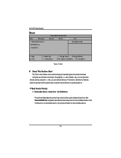
... by using the up and down arrow keys. If the first device is not a bootable device, the system will seek for boot device on system power on. GA-9IVDT Motherboard Boot Main Advanced + Removable Devices CD-ROM Drive + Hard Drive PhoenixBIOS Setup Utility Security Server Boot Exit Item Specific Help F1: Help Esc...
... by using the up and down arrow keys. If the first device is not a bootable device, the system will seek for boot device on system power on. GA-9IVDT Motherboard Boot Main Advanced + Removable Devices CD-ROM Drive + Hard Drive PhoenixBIOS Setup Utility Security Server Boot Exit Item Specific Help F1: Help Esc...
User Manual
Page 67
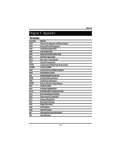
RCehvaispitoenr H6istAoprypendix Acronyms Acronyms Meaning ACPI Advanced Configuration and Power Interface APM Advanced Power Management AGP Accelerated Graphics Port AMR Audio Modem Riser ACR Advanced Communications Riser BBS BIOS Boot Specification BIOS Basic Input / Output System CPU Central Processing ...
RCehvaispitoenr H6istAoprypendix Acronyms Acronyms Meaning ACPI Advanced Configuration and Power Interface APM Advanced Power Management AGP Accelerated Graphics Port AMR Audio Modem Riser ACR Advanced Communications Riser BBS BIOS Boot Specification BIOS Basic Input / Output System CPU Central Processing ...


