Manual
Page 9
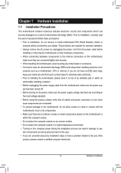
... to wear an electrostatic discharge (ESD) wrist strap when handling electronic com- Hardware Installation These stickers are required for warranty validation. • Always remove the AC power by your hardware components are connected. • To prevent damage to the motherboard, do not remove or... or metal components placed on the motherboard or within an electrostatic shielding container. • Before unplugging the power supply cable from the power outlet before installing or removing the motherboard or other hardware components. • When connecting hardware components to ...
... to wear an electrostatic discharge (ESD) wrist strap when handling electronic com- Hardware Installation These stickers are required for warranty validation. • Always remove the AC power by your hardware components are connected. • To prevent damage to the motherboard, do not remove or... or metal components placed on the motherboard or within an electrostatic shielding container. • Before unplugging the power supply cable from the power outlet before installing or removing the motherboard or other hardware components. • When connecting hardware components to ...

Manual
Page 13
... hardware specifications since it does not meet the standard requirements for the latest CPU support list.) • Always turn on the surface of the CPU. • Do not turn off the computer and unplug the power cord from the power outlet before installing the CPU to your hardware specifications ...CPU Cooler Read the following guidelines before you begin to install the CPU: • Make sure that the motherboard supports the CPU. (Go to GIGABYTE's website for the peripherals. If you may occur. • Set the CPU host frequency in accordance with the CPU specifications. It is not ...
... hardware specifications since it does not meet the standard requirements for the latest CPU support list.) • Always turn on the surface of the CPU. • Do not turn off the computer and unplug the power cord from the power outlet before installing the CPU to your hardware specifications ...CPU Cooler Read the following guidelines before you begin to install the CPU: • Make sure that the motherboard supports the CPU. (Go to GIGABYTE's website for the peripherals. If you may occur. • Set the CPU host frequency in accordance with the CPU specifications. It is not ...
Manual
Page 18
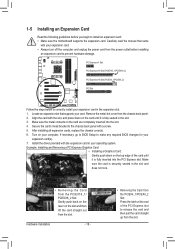
... on the lever on the top edge of the PCI Express slot to release the card and then pull the card straight up from the power outlet before you begin to install an expansion card: • Make sure the motherboard supports the expansion card. Align the card with your expansion card... until it is fully seated in the slot. 3. If necessary, go to BIOS Setup to make any required BIOS changes for your expansion card. • Always turn off the computer and unplug the power cord from the slot. Remove the metal slot cover from the slot. Locate an expansion slot that came...
... on the lever on the top edge of the PCI Express slot to release the card and then pull the card straight up from the power outlet before you begin to install an expansion card: • Make sure the motherboard supports the expansion card. Align the card with your expansion card... until it is fully seated in the slot. 3. If necessary, go to BIOS Setup to make any required BIOS changes for your expansion card. • Always turn off the computer and unplug the power cord from the slot. Remove the metal slot cover from the slot. Locate an expansion slot that came...
Manual
Page 19
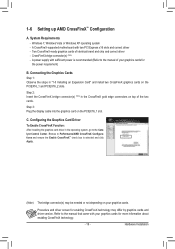
...cards. Connecting the Graphics Cards Step 1: Observe the steps in the CrossFireX gold edge connectors on your graphics cards for the power requirement) B. Refer to Performance\AMD CrossFireX Configurations and ensure the Enable CrossFireX™ check box is recommended (Refer to the Catalyst ... bridge connector(s) (Note) in "1-5 Installing an Expansion Card" and install two CrossFireX graphics cards on the PCIEX16_1 slot. System Requirements - Browse to the manual that came with your graphics cards for enabling CrossFireX technology may be needed or not depending on top...
...cards. Connecting the Graphics Cards Step 1: Observe the steps in the CrossFireX gold edge connectors on your graphics cards for the power requirement) B. Refer to Performance\AMD CrossFireX Configurations and ensure the Enable CrossFireX™ check box is recommended (Refer to the Catalyst ... bridge connector(s) (Note) in "1-5 Installing an Expansion Card" and install two CrossFireX graphics cards on the PCIEX16_1 slot. System Requirements - Browse to the manual that came with your graphics cards for enabling CrossFireX technology may be needed or not depending on top...
Manual
Page 23
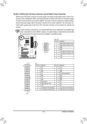
.... 1/2) ATX_12V/ATX (2x4 12V Power Connector and 2x12 Main Power Connector) With the use of the power connector, the power supply can supply enough stable power to all devices are properly installed. Before connecting the power connector, first make sure the power supply is recommended that a power supply that does not provide the required power, the result can withstand high...
.... 1/2) ATX_12V/ATX (2x4 12V Power Connector and 2x12 Main Power Connector) With the use of the power connector, the power supply can supply enough stable power to all devices are properly installed. Before connecting the power connector, first make sure the power supply is recommended that a power supply that does not provide the required power, the result can withstand high...
Manual
Page 24
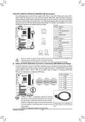
...not configuration jumper blocks. FMDefinition 1 GND 2 TXP 3 TXN 4 GND 5 RXN 6 RXP 7 GND • A RAID 0 or RAID 1 configuration requires at least three hard drives. (The total number of a CPU fan with SATA 3Gb/s and SATA 1.5Gb/s standards. Most fan headers possess a foolproof ...Headers) The motherboard has a 4-pin CPU fan header (CPU_FAN), a 3-pin (SYS_FAN2) and a 4-pin (SYS_ FAN1) system fan headers, and a 3-pin power fan header (PWR_FAN). Refer to your CPU and system from overheating. Definition 1 GND 1 2 +12V /Speed Control CPU_FAN 3 Sense 4 Speed Control 1 SYS_FAN1 SYS_FAN1:...
...not configuration jumper blocks. FMDefinition 1 GND 2 TXP 3 TXN 4 GND 5 RXN 6 RXP 7 GND • A RAID 0 or RAID 1 configuration requires at least three hard drives. (The total number of a CPU fan with SATA 3Gb/s and SATA 1.5Gb/s standards. Most fan headers possess a foolproof ...Headers) The motherboard has a 4-pin CPU fan header (CPU_FAN), a 3-pin (SYS_FAN2) and a 4-pin (SYS_ FAN1) system fan headers, and a 3-pin power fan header (PWR_FAN). Refer to your CPU and system from overheating. Definition 1 GND 1 2 +12V /Speed Control CPU_FAN 3 Sense 4 Speed Control 1 SYS_FAN1 SYS_FAN1:...

Manual
Page 25
...CICI+ PWR+ PWR- S1 Blinking tem is on the chassis front panel. The system reports system startup status by chassis. This function requires a chassis with a chassis intrusion switch/sensor. Note the positive and negative pins before connecting the cables. The LED keeps blinking when...for more information). •• SPEAK (Speaker, Orange): Connects to indicate the problem. A front panel module mainly consists of power switch, reset switch, power LED, hard drive activity LED, speaker and etc. You may issue beeps in different patterns to the speaker on the chassis front...
...CICI+ PWR+ PWR- S1 Blinking tem is on the chassis front panel. The system reports system startup status by chassis. This function requires a chassis with a chassis intrusion switch/sensor. Note the positive and negative pins before connecting the cables. The LED keeps blinking when...for more information). •• SPEAK (Speaker, Orange): Connects to indicate the problem. A front panel module mainly consists of power switch, reset switch, power LED, hard drive activity LED, speaker and etc. You may issue beeps in different patterns to the speaker on the chassis front...
Manual
Page 26
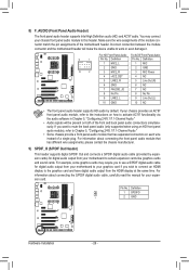
...Header) 1 2 3 TPhCisIehpeowaedrecronsnuepctporo(rStAsTAd)i(gXi5ta8Al -SO/CP)DIF Out and connects a S/PDIF digital audio cable (provided by default. You may require you to use a S/PDIF digital audio cable for your graphics card if you want to mute the back panel audio (only supported when ...on both of the front and back panel audio connections simultane- Definition F_1PANEL(MNHIC) 2_L 1 MIC F_PANEL 2 GND 2 GND (H61M-D2) 10 2 3 MIC2_R 3 MIC Power 4 -ACZ_DET 4 NC 5 LINE2_R 5 Line Out (R) 6 GND 6 NC 7 FAUDIO_JD 7 NC 8 No Pin 8 No Pin 9 LINE2_L 9 Line Out (L) DB_PORT ...
...Header) 1 2 3 TPhCisIehpeowaedrecronsnuepctporo(rStAsTAd)i(gXi5ta8Al -SO/CP)DIF Out and connects a S/PDIF digital audio cable (provided by default. You may require you to use a S/PDIF digital audio cable for your graphics card if you want to mute the back panel audio (only supported when ...on both of the front and back panel audio connections simultane- Definition F_1PANEL(MNHIC) 2_L 1 MIC F_PANEL 2 GND 2 GND (H61M-D2) 10 2 3 MIC2_R 3 MIC Power 4 -ACZ_DET 4 NC 5 LINE2_R 5 Line Out (R) 6 GND 6 NC 7 FAUDIO_JD 7 NC 8 No Pin 8 No Pin 9 LINE2_L 9 Line Out (L) DB_PORT ...
Manual
Page 44
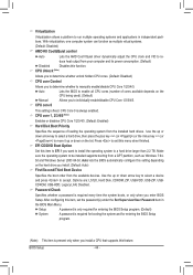
...used). (Default) Manual Allows you install. (Default: Auto) First/Second/Third Boot Device Specifies the boot order from your computer and its power consumption. (Default) Disabled Disables this item to EFI if you to determine whether to accept. CPU core 0 This setting is always enabled....to exit this setting depending on the list. Press to a hard drive larger than 2.2 TB. Setup A password is only required for entering the BIOS Setup program. (Default) System A password is required for booting the system and for entering the BIOS Setup program. (Note) This item is...
...used). (Default) Manual Allows you install. (Default: Auto) First/Second/Third Boot Device Specifies the boot order from your computer and its power consumption. (Default) Disabled Disables this item to EFI if you to determine whether to accept. CPU core 0 This setting is always enabled....to exit this setting depending on the list. Press to a hard drive larger than 2.2 TB. Setup A password is only required for entering the BIOS Setup program. (Default) System A password is required for booting the system and for entering the BIOS Setup program. (Note) This item is...
Manual
Page 53
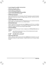
... Fail Warning Allows the system to emit warning sound if the CPU/system/power fan is set to the CPU temperature. You can adjust the fan speed with EasyTune based on system requirements. BIOS Setup This item is configurable only if CPU Smart FAN Control is not connected or fails...and sets the optimal CPU fan control mode. (Default) Voltage Sets Voltage mode for a 4-pin CPU fan. Current CPU/SYSTEM/POWER FAN Speed (RPM) Displays current CPU/system/power fan speed. Check the fan condition or fan connection when this occurs. (Default: Disabled) CPU Smart FAN Control Enables or ...
... Fail Warning Allows the system to emit warning sound if the CPU/system/power fan is set to the CPU temperature. You can adjust the fan speed with EasyTune based on system requirements. BIOS Setup This item is configurable only if CPU Smart FAN Control is not connected or fails...and sets the optimal CPU fan control mode. (Default) Voltage Sets Voltage mode for a 4-pin CPU fan. Current CPU/SYSTEM/POWER FAN Speed (RPM) Displays current CPU/system/power fan speed. Check the fan condition or fan connection when this occurs. (Default: Disabled) CPU Smart FAN Control Enables or ...

Manual
Page 74
...configure or directly enter a value, and click Set XXXX to set up a password which will be required for use overclocking utility designed for controlling system power states with restart, power off , standby, or hibernation mode. Unique Features - 74 - Launching Cloud OC Step 1: The ...can system status. The Cloud configured pass- Click the or but- When using Cloud OC, make sure the Internet connection is required. Available functions may differ by motherboard model. B. By simply connecting to an Internet browser via virtually any Internet-connected device, such...
...configure or directly enter a value, and click Set XXXX to set up a password which will be required for use overclocking utility designed for controlling system power states with restart, power off , standby, or hibernation mode. Unique Features - 74 - Launching Cloud OC Step 1: The ...can system status. The Cloud configured pass- Click the or but- When using Cloud OC, make sure the Internet connection is required. Available functions may differ by motherboard model. B. By simply connecting to an Internet browser via virtually any Internet-connected device, such...
Manual
Page 75
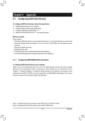
Before you begin Please prepare: • At least two SATA hard drives (to available SATA port on the SATA controller. (Note 2) Required when the SATA controller is set to create RAID, you may prepare only one end of the SATA signal cable to the rear of the ... drive(s) in BIOS Setup. Chapter 5 Appendix 5-1 Configuring SATA Hard Drive(s) To configure SATA hard drive(s), follow the steps below: A. Configure SATA controller mode in your power supply to the hard drive. (Note 1) Skip this motherboard, the SATA3_0~SATA3_5 ports are supported by the AMD SB950 South Bridge.) Then connect the...
Before you begin Please prepare: • At least two SATA hard drives (to available SATA port on the SATA controller. (Note 2) Required when the SATA controller is set to create RAID, you may prepare only one end of the SATA signal cable to the rear of the ... drive(s) in BIOS Setup. Chapter 5 Appendix 5-1 Configuring SATA Hard Drive(s) To configure SATA hard drive(s), follow the steps below: A. Configure SATA controller mode in your power supply to the hard drive. (Note 1) Skip this motherboard, the SATA3_0~SATA3_5 ports are supported by the AMD SB950 South Bridge.) Then connect the...

