Manual
Page 9
...Turning on the motherboard, make sure the power supply voltage has been set according to the local voltage standard. •• Before using the product, please verify that all cables and power connectors of your dealer. These stickers are required for warranty validation. •• Always... remove the AC power by your hardware components are uncertain about any metal leads or connectors. •&#...
...Turning on the motherboard, make sure the power supply voltage has been set according to the local voltage standard. •• Before using the product, please verify that all cables and power connectors of your dealer. These stickers are required for warranty validation. •• Always... remove the AC power by your hardware components are uncertain about any metal leads or connectors. •&#...
Manual
Page 13
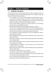
...of the CPU. •• Do not turn off the computer and unplug the power cord from the power outlet before you begin to install the CPU: •• Make sure that ...CPU cannot be set the frequency beyond hardware specifications since it does not meet the standard requirements for the latest CPU support list.) •• Always turn on the computer if ...the CPU cooler is not recommended that the motherboard supports the CPU. (Go to GIGABYTE's website for the peripherals. 1-3 Installing the CPU and CPU Cooler Read the following guidelines before ...
...of the CPU. •• Do not turn off the computer and unplug the power cord from the power outlet before you begin to install the CPU: •• Make sure that ...CPU cannot be set the frequency beyond hardware specifications since it does not meet the standard requirements for the latest CPU support list.) •• Always turn on the computer if ...the CPU cooler is not recommended that the motherboard supports the CPU. (Go to GIGABYTE's website for the peripherals. 1-3 Installing the CPU and CPU Cooler Read the following guidelines before ...
Manual
Page 18
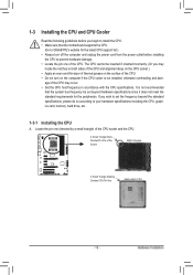
... in the slot. 3. Align the card with your expansion card. •• Always turn off the computer and unplug the power cord from the power outlet before you begin to make any required BIOS changes for your expansion card(s). 7. Install the driver provided with a screw. 5. Make sure the card is fully inserted into...
... in the slot. 3. Align the card with your expansion card. •• Always turn off the computer and unplug the power cord from the power outlet before you begin to make any required BIOS changes for your expansion card(s). 7. Install the driver provided with a screw. 5. Make sure the card is fully inserted into...
Manual
Page 22
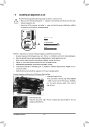
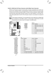
... No. 1 2 3 4 5 6 7 8 9 10 11 12 Definition Pin No. 3.3V 13 3.3V 14 GND 15 +5V 16 GND 17 +5V 18 GND 19 Power Good 20 5VSB (stand by +5V) 21 +12V 22 +12V (Only for 2x12-pin ATX) 23 3.3V (Only for 2x12-pin ATX) 24 Definition 3.3V... for 2x12-pin ATX) Hardware Installation - 22 - To meet expansion requirements, it is used (500W or greater). If a power supply is recommended that a power supply that can withstand high power consumption be used that does not provide the required power, the result can supply enough stable power to all devices are properly installed.
... No. 1 2 3 4 5 6 7 8 9 10 11 12 Definition Pin No. 3.3V 13 3.3V 14 GND 15 +5V 16 GND 17 +5V 18 GND 19 Power Good 20 5VSB (stand by +5V) 21 +12V 22 +12V (Only for 2x12-pin ATX) 23 3.3V (Only for 2x12-pin ATX) 24 Definition 3.3V... for 2x12-pin ATX) Hardware Installation - 22 - To meet expansion requirements, it is used (500W or greater). If a power supply is recommended that a power supply that can withstand high power consumption be used that does not provide the required power, the result can supply enough stable power to all devices are properly installed.
Manual
Page 23
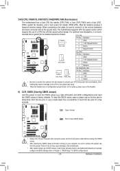
...SYS_FAN1: Pin No. Do not place a jumper cap on your computer, be installed inside the chassis. The motherboard supports CPU fan speed control, which requires the use a metal object like a screwdriver to remove the jumper cap from the jumper. Hardware Installation Definition 1 GND 1 SYS_FAN1 2 +12V /... The motherboard has a 4-pin CPU fan header (CPU_FAN), a 3-pin (SYS_FAN2) and a 4-pin (SYS_ FAN1) system fan headers, and a 3-pin power fan header (PWR_FAN). Definition 1 GND 2 +12V 3 Sense •• Be sure to connect fan cables to the fan headers to prevent your computer ...
...SYS_FAN1: Pin No. Do not place a jumper cap on your computer, be installed inside the chassis. The motherboard supports CPU fan speed control, which requires the use a metal object like a screwdriver to remove the jumper cap from the jumper. Hardware Installation Definition 1 GND 1 SYS_FAN1 2 +12V /... The motherboard has a 4-pin CPU fan header (CPU_FAN), a 3-pin (SYS_FAN2) and a 4-pin (SYS_ FAN1) system fan headers, and a 3-pin power fan header (PWR_FAN). Definition 1 GND 2 +12V 3 Sense •• Be sure to connect fan cables to the fan headers to prevent your computer ...
Manual
Page 24
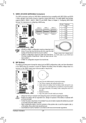
...three hard drives. Each SATA connector supports a single SATA device. even number.) •• A RAID 10 configuration requires four hard drives. 8) BAT (Battery) The battery provides power to keep the values (such as BIOS configurations, date, and time information) in the CMOS when the computer is ...number. Danger of explosion if the battery is turned off your SATA hard (The total number of •• A RAID 5 configuration requires at least two hard drives. If more than two hard drives are compatible with an incorrect model. •• Contact the place of...
...three hard drives. Each SATA connector supports a single SATA device. even number.) •• A RAID 10 configuration requires four hard drives. 8) BAT (Battery) The battery provides power to keep the values (such as BIOS configurations, date, and time information) in the CMOS when the computer is ...number. Danger of explosion if the battery is turned off your SATA hard (The total number of •• A RAID 5 configuration requires at least two hard drives. If more than two hard drives are compatible with an incorrect model. •• Contact the place of...
Manual
Page 25
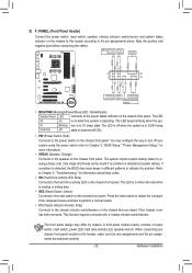
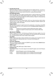
...by chassis. One single short beep will be heard if no problem is operating. A front panel module mainly consists of power switch, reset switch, power LED, hard drive activity LED, speaker and etc. The LED keeps blinking when the sys- If a problem is detected...detected at system startup. You may differ by issuing a beep code. This function requires a chassis with a chassis intrusion switch/sensor. When connecting your system using the power switch (refer to Chapter 2, "BIOS Setup," "Power Management Setup," for information about beep codes. •• HD (Hard Drive...
...by chassis. One single short beep will be heard if no problem is operating. A front panel module mainly consists of power switch, reset switch, power LED, hard drive activity LED, speaker and etc. The LED keeps blinking when the sys- If a problem is detected...detected at system startup. You may differ by issuing a beep code. This function requires a chassis with a chassis intrusion switch/sensor. When connecting your system using the power switch (refer to Chapter 2, "BIOS Setup," "Power Management Setup," for information about beep codes. •• HD (Hard Drive...
Manual
Page 26
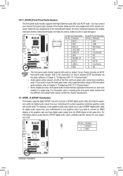
..., please contact the chassis manufacturer. Definition 9 1 1 MIC2_L F_PANEL(NH) 2 GND Pin No. 1 2 Definition MIC GND F_PANEL (H61M-D2) 10 2 3 MIC2_R 4 -ACZ_DET 3 MIC Power 4 NC 5 LINE2_R 5 Line Out (R) 6 GND 6 NC 7 FAUDIO_JD 7 NC 8 No Pin 8 No Pin 9 LINE2_L 9 Line Out (L) DIP 1 23 1 10 GND 10 NC...using an HD front panel Voltage measauruedmieontmmodduulele(X)5,8rAe-fOeCr)to the instructions on each wire instead of the motherboard header. You may require you to use a S/PDIF digital audio cable for digital audio output from the HDMI display at the same time. DIP 11...
..., please contact the chassis manufacturer. Definition 9 1 1 MIC2_L F_PANEL(NH) 2 GND Pin No. 1 2 Definition MIC GND F_PANEL (H61M-D2) 10 2 3 MIC2_R 4 -ACZ_DET 3 MIC Power 4 NC 5 LINE2_R 5 Line Out (R) 6 GND 6 NC 7 FAUDIO_JD 7 NC 8 No Pin 8 No Pin 9 LINE2_L 9 Line Out (L) DIP 1 23 1 10 GND 10 NC...using an HD front panel Voltage measauruedmieontmmodduulele(X)5,8rAe-fOeCr)to the instructions on each wire instead of the motherboard header. You may require you to use a S/PDIF digital audio cable for digital audio output from the HDMI display at the same time. DIP 11...

Manual
Page 37
...DQS Training Control Enables or disables memory DQS training each time the system restarts. (Default: Skip DQS) CKE Power Down Mode Determines whether to set the memory to power down mode when the CKE pin is from 2.060V to set the system voltages. Note: Increasing CPU voltage ...whether to increase memory performance and stability. (Default: Enabled) Bank Interleaving Enables or disables memory bank interleaving. Normal Supplies the CPU PLL voltage as required. CKE Setup Time Options are : Auto (default), 0/64~31/64. BIOS Setup Addr/Cmd Fine Delay Options are : Auto (default), 1/...
...DQS Training Control Enables or disables memory DQS training each time the system restarts. (Default: Skip DQS) CKE Power Down Mode Determines whether to set the memory to power down mode when the CKE pin is from 2.060V to set the system voltages. Note: Increasing CPU voltage ...whether to increase memory performance and stability. (Default: Enabled) Bank Interleaving Enables or disables memory bank interleaving. Normal Supplies the CPU PLL voltage as required. CKE Setup Time Options are : Auto (default), 0/64~31/64. BIOS Setup Addr/Cmd Fine Delay Options are : Auto (default), 1/...
Manual
Page 42
... this item, set the password(s) under the Set Supervisor/User Password item in a low-power mode that appears off. (Default: Disabled) Full Screen LOGO Show Allows you enter BIOS Setup... the PCI graphics card as the first display. Make sure the operating system to display the GIGABYTE Logo at system startup. HDD S.M.A.R.T. Disabled displays normal POST message. (Default: Enabled) IOMMU...the installed PCI graphics card or the PCI Express graphics card. Setup A password is only required for entering the BIOS Setup program. (Default) System A password is installed. (Default:...
... this item, set the password(s) under the Set Supervisor/User Password item in a low-power mode that appears off. (Default: Disabled) Full Screen LOGO Show Allows you enter BIOS Setup... the PCI graphics card as the first display. Make sure the operating system to display the GIGABYTE Logo at system startup. HDD S.M.A.R.T. Disabled displays normal POST message. (Default: Enabled) IOMMU...the installed PCI graphics card or the PCI Express graphics card. Setup A password is only required for entering the BIOS Setup program. (Default) System A password is installed. (Default:...
Manual
Page 49
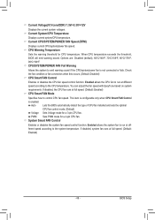
... adjust the fan speed with EasyTune based on system requirements. Current System/CPU Temperature Displays current system/CPU temperature. PWM Sets PWM mode for CPU temperature. Current CPU/SYSTEM/POWER FAN Speed (RPM) Displays current CPU/system/power fan speed. If disabled, the CPU fan runs at... according to run at full speed. (Default: Enabled) CPU Smart FAN Mode Specifies how to emit warning sound if the CPU/system/power fan is enabled. Current Voltage(V) Vcore/DDR3 1.5V/+3.3V/+12V Displays the current system voltages. CPU Warning Temperature Sets the warning threshold ...
... adjust the fan speed with EasyTune based on system requirements. Current System/CPU Temperature Displays current system/CPU temperature. PWM Sets PWM mode for CPU temperature. Current CPU/SYSTEM/POWER FAN Speed (RPM) Displays current CPU/system/power fan speed. If disabled, the CPU fan runs at... according to run at full speed. (Default: Enabled) CPU Smart FAN Mode Specifies how to emit warning sound if the CPU/system/power fan is enabled. Current Voltage(V) Vcore/DDR3 1.5V/+3.3V/+12V Displays the current system voltages. CPU Warning Temperature Sets the warning threshold ...
Manual
Page 70
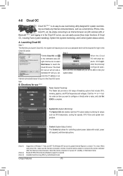
... Cloud OC Step 1: The first time you launch Cloud OC, the system will request you to set up a password which will be required for controlling system power states with restart, power off , standby, or hibernation mode. The Cloud configured pass- Bluetooth PAN (Personal Area Network) support is normal. ton under an item you...
... Cloud OC Step 1: The first time you launch Cloud OC, the system will request you to set up a password which will be required for controlling system power states with restart, power off , standby, or hibernation mode. The Cloud configured pass- Bluetooth PAN (Personal Area Network) support is normal. ton under an item you...
Manual
Page 71
Before you begin Please prepare: •• At least two SATA hard drives (to AHCI or RAID mode. - 71 - Then connect the power connector from your power supply to the hard drive. (Note 1) Skip this step if you use two hard drives with identical model and capacity). B. Appendix Configure SATA ...SATA signal cable to the rear of the SATA hard drive and the other end to available SATA port on the SATA controller. (Note 2) Required when the SATA controller is set to ensure optimal performance, it is recommended that you do not want to create RAID array on the motherboard...
Before you begin Please prepare: •• At least two SATA hard drives (to AHCI or RAID mode. - 71 - Then connect the power connector from your power supply to the hard drive. (Note 1) Skip this step if you use two hard drives with identical model and capacity). B. Appendix Configure SATA ...SATA signal cable to the rear of the SATA hard drive and the other end to available SATA port on the SATA controller. (Note 2) Required when the SATA controller is set to ensure optimal performance, it is recommended that you do not want to create RAID array on the motherboard...


