Manual
Page 3
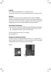
... Copyright © 2011 GIGA-BYTE TECHNOLOGY CO., LTD. The trademarks mentioned in the use of GIGABYTE. Documentation Classifications In order to assist in this product, GIGABYTE provides the following types of documentations: For quick set-up of the product, read the...User's Manual. For product-related information, check on our website at: http://www.gigabyte.com Identifying Your Motherboard Revision The revision number on your motherboard revision before updating motherboard BIOS, drivers, or when looking for technical information. Disclaimer Information in this manual may ...
... Copyright © 2011 GIGA-BYTE TECHNOLOGY CO., LTD. The trademarks mentioned in the use of GIGABYTE. Documentation Classifications In order to assist in this product, GIGABYTE provides the following types of documentations: For quick set-up of the product, read the...User's Manual. For product-related information, check on our website at: http://www.gigabyte.com Identifying Your Motherboard Revision The revision number on your motherboard revision before updating motherboard BIOS, drivers, or when looking for technical information. Disclaimer Information in this manual may ...
Manual
Page 4
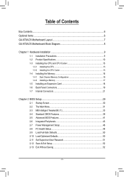
Table of Contents Box Contents...6 Optional Items...6 GA-970A-D3 Motherboard Layout 7 GA-970A-D3 Motherboard Block Diagram 8 Chapter 1 Hardware Installation 9 1-1 Installation Precautions 9 1-2 Product Specifications 10 1-3 Installing the CPU and CPU ...Installing an Expansion Card 18 1-6 Back Panel Connectors 19 1-7 Internal Connectors 21 Chapter 2 BIOS Setup 29 2-1 Startup Screen 30 2-2 The Main Menu 31 2-3 MB Intelligent Tweaker(M.I.T 33 2-4 Standard CMOS Features 39 2-5 Advanced BIOS Features 41 2-6 Integrated Peripherals 43 2-7 Power Management Setup 46 2-8 PC Health Status ...
Table of Contents Box Contents...6 Optional Items...6 GA-970A-D3 Motherboard Layout 7 GA-970A-D3 Motherboard Block Diagram 8 Chapter 1 Hardware Installation 9 1-1 Installation Precautions 9 1-2 Product Specifications 10 1-3 Installing the CPU and CPU ...Installing an Expansion Card 18 1-6 Back Panel Connectors 19 1-7 Internal Connectors 21 Chapter 2 BIOS Setup 29 2-1 Startup Screen 30 2-2 The Main Menu 31 2-3 MB Intelligent Tweaker(M.I.T 33 2-4 Standard CMOS Features 39 2-5 Advanced BIOS Features 41 2-6 Integrated Peripherals 43 2-7 Power Management Setup 46 2-8 PC Health Status ...

Manual
Page 5
... 54 3-4 Contact...55 3-5 System...55 3-6 Download Center 56 3-7 New Utilities...56 Chapter 4 Unique Features 57 4-1 Xpress Recovery2 57 4-2 BIOS Update Utilities 60 4-2-1 Updating the BIOS with the Q-Flash Utility 60 4-2-2 Updating the BIOS with the @BIOS Utility 63 4-3 EasyTune 6...64 4-4 Easy Energy Saver 65 4-5 Q-Share...67 4-6 SMART Recovery 68 4-7 Auto Green...69 4-8 Cloud OC...
... 54 3-4 Contact...55 3-5 System...55 3-6 Download Center 56 3-7 New Utilities...56 Chapter 4 Unique Features 57 4-1 Xpress Recovery2 57 4-2 BIOS Update Utilities 60 4-2-1 Updating the BIOS with the Q-Flash Utility 60 4-2-2 Updating the BIOS with the @BIOS Utility 63 4-3 EasyTune 6...64 4-4 Easy Energy Saver 65 4-5 Q-Share...67 4-6 SMART Recovery 68 4-7 Auto Green...69 4-8 Cloud OC...
Manual
Page 8
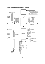
GA-970A-D3 Motherboard Block Diagram 1 PCI Express x16 AM3+/AM3 CPU CPU CLK+/- (200 MHz) DDR3 2000 (O.C.)/1866/1600/ 1333/1066 MHz Dual Channel Memory PCIe CLK (... x1 PCI Express Bus PCI Express Bus x4 PCIe CLK (100 MHz) 1 PCI Express x4 PCI Bus 6 SATA 6Gb/s AMD SB950 14 USB 2.0/1.1 CODEC Dual BIOS LPC Bus iTE IT8720 COM Port PS/2 KB/Mouse Surround Speaker Out Center/Subwoofer Speaker Out Side Speaker Out MIC Line Out Line In S/PDIF...
GA-970A-D3 Motherboard Block Diagram 1 PCI Express x16 AM3+/AM3 CPU CPU CLK+/- (200 MHz) DDR3 2000 (O.C.)/1866/1600/ 1333/1066 MHz Dual Channel Memory PCIe CLK (... x1 PCI Express Bus PCI Express Bus x4 PCIe CLK (100 MHz) 1 PCI Express x4 PCI Bus 6 SATA 6Gb/s AMD SB950 14 USB 2.0/1.1 CODEC Dual BIOS LPC Bus iTE IT8720 COM Port PS/2 KB/Mouse Surround Speaker Out Center/Subwoofer Speaker Out Side Speaker Out MIC Line Out Line In S/PDIF...
Manual
Page 11
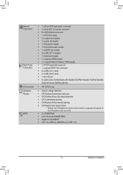
Hardware Installation Internal Connectors Back Panel Connectors I/O Controller Hardware Monitor BIOS ŠŠ 1 x 24-pin ATX main power connector ŠŠ 1 x 8-pin ATX 12V power connector ŠŠ 6 x SATA 6Gb/s connectors ŠŠ 1 x CPU fan header &#... speed control function is supported will depend on the CPU/system cooler you install. ŠŠ 2 x 32 Mbit flash ŠŠ Use of licensed AWARD BIOS ŠŠ Support for DualBIOS™ ŠŠ PnP 1.0a, DMI 2.0, SM...
Hardware Installation Internal Connectors Back Panel Connectors I/O Controller Hardware Monitor BIOS ŠŠ 1 x 24-pin ATX main power connector ŠŠ 1 x 8-pin ATX 12V power connector ŠŠ 6 x SATA 6Gb/s connectors ŠŠ 1 x CPU fan header &#... speed control function is supported will depend on the CPU/system cooler you install. ŠŠ 2 x 32 Mbit flash ŠŠ Use of licensed AWARD BIOS ŠŠ Support for DualBIOS™ ŠŠ PnP 1.0a, DMI 2.0, SM...
Manual
Page 12
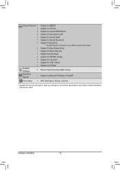
...;Š Support for Q-Flash ŠŠ Support for Xpress BIOS Rescue ŠŠ Support for Download Center ŠŠ Support for Xpress Install ŠŠ Support for Xpress Recovery2 ŠŠ Support for EasyTune * Available ...
...;Š Support for Q-Flash ŠŠ Support for Xpress BIOS Rescue ŠŠ Support for Download Center ŠŠ Support for Xpress Install ŠŠ Support for Xpress Recovery2 ŠŠ Support for EasyTune * Available ...
Manual
Page 16
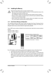
...memory modules.) •• Always turn off the computer and unplug the power cord from the power outlet before installing the memory to GIGABYTE's website for optimum performance. Enabling Dual Channel memory mode will automatically detect the specifications and capacity of the same capacity, brand, speed...DDR3_1 and DDR3_2 sockets. For optimum performance, when enabling Dual Channel mode with two or four memory modules, it is installed, the BIOS will double the original memory bandwidth. A memory module can be enabled if only one direction. If you begin to insert the memory,...
...memory modules.) •• Always turn off the computer and unplug the power cord from the power outlet before installing the memory to GIGABYTE's website for optimum performance. Enabling Dual Channel memory mode will automatically detect the specifications and capacity of the same capacity, brand, speed...DDR3_1 and DDR3_2 sockets. For optimum performance, when enabling Dual Channel mode with two or four memory modules, it is installed, the BIOS will double the original memory bandwidth. A memory module can be enabled if only one direction. If you begin to insert the memory,...
Manual
Page 18
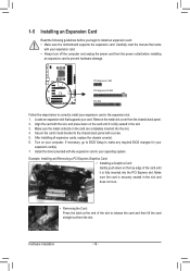
... straight out from the chassis back panel. 2. Secure the card's metal bracket to make any required BIOS changes for your operating system. After installing all expansion cards, replace the chassis cover(s). 6. If necessary, go to BIOS Setup to the chassis back panel with the expansion card in the slot and does not...
... straight out from the chassis back panel. 2. Secure the card's metal bracket to make any required BIOS changes for your operating system. After installing all expansion cards, replace the chassis cover(s). 6. If necessary, go to BIOS Setup to the chassis back panel with the expansion card in the slot and does not...
Manual
Page 23
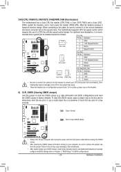
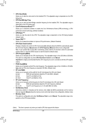
...the jumper cap from overheating. When connecting a fan cable, be sure to touch the two pins for BIOS configurations). - 23 - date information and BIOS configurations) and reset the CMOS values to clear the CMOS values (e.g. The motherboard supports CPU fan speed control...to prevent your computer, be installed inside the chassis. To clear the CMOS values, place a jumper cap on the two pins to Chapter 2, "BIOS Setup," for a few seconds. Hardware Installation 3/4/5) CPU_FAN/SYS_FAN1/SYS_FAN2/PWR_FAN (Fan Headers) The motherboard has a 4-pin CPU fan header (CPU_FAN), a...
...the jumper cap from overheating. When connecting a fan cable, be sure to touch the two pins for BIOS configurations). - 23 - date information and BIOS configurations) and reset the CMOS values to clear the CMOS values (e.g. The motherboard supports CPU fan speed control...to prevent your computer, be installed inside the chassis. To clear the CMOS values, place a jumper cap on the two pins to Chapter 2, "BIOS Setup," for a few seconds. Hardware Installation 3/4/5) CPU_FAN/SYS_FAN1/SYS_FAN2/PWR_FAN (Fan Headers) The motherboard has a 4-pin CPU fan header (CPU_FAN), a...
Manual
Page 24
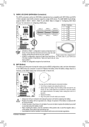
...(s)," for one . even number.) •• A RAID 10 configuration requires four hard drives. 8) BAT (Battery) The battery provides power to keep the values (such as BIOS configurations, date, and time information) in accordance with an equivalent one minute. (Or use a metal object like a screwdriver to touch the positive and negative terminals...
...(s)," for one . even number.) •• A RAID 10 configuration requires four hard drives. 8) BAT (Battery) The battery provides power to keep the values (such as BIOS configurations, date, and time information) in accordance with an equivalent one minute. (Or use a metal object like a screwdriver to touch the positive and negative terminals...
Manual
Page 25
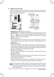
...Power Switch, Red): Connects to the power switch on the chassis front panel. When connecting your system using the power switch (refer to Chapter 2, "BIOS Setup," "Power Management Setup," for information about beep codes. •• HD (Hard Drive Activity LED, Blue) Connects to indicate the problem....pin assignments below. The system reports system startup status by chassis. One single short beep will be heard if no problem is detected, the BIOS may differ by issuing a beep code. The LED is off when the system is reading or writing data. •• RES (Reset...
...Power Switch, Red): Connects to the power switch on the chassis front panel. When connecting your system using the power switch (refer to Chapter 2, "BIOS Setup," "Power Management Setup," for information about beep codes. •• HD (Hard Drive Activity LED, Blue) Connects to indicate the problem....pin assignments below. The system reports system startup status by chassis. One single short beep will be heard if no problem is detected, the BIOS may differ by issuing a beep code. The LED is off when the system is reading or writing data. •• RES (Reset...
Manual
Page 26
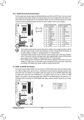
... Power 4 NC 5 LINE2_R 5 Line Out (R) 6 GND 6 NC 7 FAUDIO_JD 7 NC 8 No Pin 8 No Pin 9 LINE2_L 9 Line Out (L) DIP 1 23 1 10 GND 10 NC DIP 1 23 1 DB_PORT BIOS Switcher (X58A-OC) • The front panel audio header supports HD audio by expansion cards) for your motherboard to work or even damage it. You...
... Power 4 NC 5 LINE2_R 5 Line Out (R) 6 GND 6 NC 7 FAUDIO_JD 7 NC 8 No Pin 8 No Pin 9 LINE2_L 9 Line Out (L) DIP 1 23 1 10 GND 10 NC DIP 1 23 1 DB_PORT BIOS Switcher (X58A-OC) • The front panel audio header supports HD audio by expansion cards) for your motherboard to work or even damage it. You...
Manual
Page 28
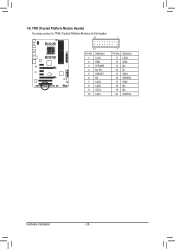
Definition 1 LCLK 2 GND 3 LFRAME 4 No Pin 5 LRESET 6 NC 7 LAD3 8 LAD2 9 VCC3 10 LAD1 1 Voltage measurement module(X58A-OC) PWM 2 Pin No. Definition 11 LAD0 1 12 GND PCIe power connector (SATA)(X58A-OC) 13 NC 14 ID 15 SB3V 16 SERIRQ 17 GND 18 NC 19 NC 20 SUSCLK Hardware Installation - 28 - DB_PORT BIOS S 1 1 14) TPM (Trusted Platform Module Header) You may connect a TPM (Trusted Platform Module) to this header. 19 TPM w/housing 20 Pin No.
Definition 1 LCLK 2 GND 3 LFRAME 4 No Pin 5 LRESET 6 NC 7 LAD3 8 LAD2 9 VCC3 10 LAD1 1 Voltage measurement module(X58A-OC) PWM 2 Pin No. Definition 11 LAD0 1 12 GND PCIe power connector (SATA)(X58A-OC) 13 NC 14 ID 15 SB3V 16 SERIRQ 17 GND 18 NC 19 NC 20 SUSCLK Hardware Installation - 28 - DB_PORT BIOS S 1 1 14) TPM (Trusted Platform Module Header) You may connect a TPM (Trusted Platform Module) to this header. 19 TPM w/housing 20 Pin No.
Manual
Page 29
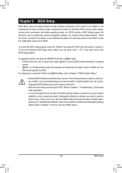
... to) to prevent system instability or other unexpected results. To upgrade the BIOS, use either the GIGABYTE Q-Flash or @BIOS utility. •• Q-Flash allows the user to quickly and easily upgrade or back up BIOS without entering the operating system. •• @BIOS is a Windows-based utility that you do it is recommended that...
... to) to prevent system instability or other unexpected results. To upgrade the BIOS, use either the GIGABYTE Q-Flash or @BIOS utility. •• Q-Flash allows the user to quickly and easily upgrade or back up BIOS without entering the operating system. •• @BIOS is a Windows-based utility that you do it is recommended that...
Manual
Page 30
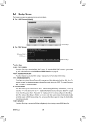
To show the BIOS POST screen. GA-970A-D3 D2 . . . . : BIOS Setup : XpressRecovery2 : Boot Menu : Qflash 04/29/2011-RD970-SB950-7A66FG03C-00 Function Keys Function Keys Function Keys: : POST SCREEN Press the key to Xpress ... boot device setting as needed. : Q-FLASH Press the key to access the Q-Flash utility directly without having to set the first boot device without entering BIOS Setup. The system will still be used for one time only. 2-1 Startup Screen The following screens may appear when the computer boots. To exit Boot...
To show the BIOS POST screen. GA-970A-D3 D2 . . . . : BIOS Setup : XpressRecovery2 : Boot Menu : Qflash 04/29/2011-RD970-SB950-7A66FG03C-00 Function Keys Function Keys Function Keys: : POST SCREEN Press the key to Xpress ... boot device setting as needed. : Q-FLASH Press the key to access the Q-Flash utility directly without having to set the first boot device without entering BIOS Setup. The system will still be used for one time only. 2-1 Startup Screen The following screens may appear when the computer boots. To exit Boot...

Manual
Page 31
... Exit Without Saving ESC: Quit F8: Q-Flash Select Item F10: Save & Exit Setup Change CPU's Clock & Voltage F11: Save CMOS to BIOS F12: Load CMOS from BIOS BIOS Setup Program Function Keys Move the selection bar to select an item Execute command or enter the submenu Main Menu: Exit the...side of function keys available for the current submenus Access the Q-Flash utility Display system information Save all the changes and exit the BIOS Setup program Save CMOS to access more advanced options. •• When the system is displayed on the bottom line of the ...
... Exit Without Saving ESC: Quit F8: Q-Flash Select Item F10: Save & Exit Setup Change CPU's Clock & Voltage F11: Save CMOS to BIOS F12: Load CMOS from BIOS BIOS Setup Program Function Keys Move the selection bar to select an item Execute command or enter the submenu Main Menu: Exit the...side of function keys available for the current submenus Access the Q-Flash utility Display system information Save all the changes and exit the BIOS Setup program Save CMOS to access more advanced options. •• When the system is displayed on the bottom line of the ...

Manual
Page 32
...menu to configure the system time and date, hard drive types, and the type of errors that stop the system boot, etc. Advanced BIOS Features Use this menu to configure the device boot order, advanced features available on the CPU, and the primary display adapter. Integrated Peripherals... a profile created before, without the hassles of the and keys (For the Main Menu Only) F11: Save CMOS to BIOS This function allows you to view the BIOS settings but not to 8 profiles (Profile 1-8) and name each profile. You can also carry out this task.) Exit Without...
...menu to configure the system time and date, hard drive types, and the type of errors that stop the system boot, etc. Advanced BIOS Features Use this menu to configure the device boot order, advanced features available on the CPU, and the primary display adapter. Integrated Peripherals... a profile created before, without the hassles of the and keys (For the Main Menu Only) F11: Save CMOS to BIOS This function allows you to view the BIOS settings but not to 8 profiles (Profile 1-8) and name each profile. You can also carry out this task.) Exit Without...
Manual
Page 33
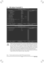
... you not to alter the default settings to prevent system instability or other unexpected results. (Inadequately altering the settings may result in damage to boot. BIOS Setup Core Performance Boost (Note) CPB Ratio (Note) Turbo CPB (Note) CPU Host Clock Control x CPU Frequency(MHz) PCIE Clock(MHz) HT Link Width HT...
... you not to alter the default settings to prevent system instability or other unexpected results. (Inadequately altering the settings may result in damage to boot. BIOS Setup Core Performance Boost (Note) CPB Ratio (Note) Turbo CPB (Note) CPU Host Clock Control x CPU Frequency(MHz) PCIE Clock(MHz) HT Link Width HT...
Manual
Page 34
... set the PCIe clock frequency. This option is configurable only when CPU Host Clock Control is highly recommended that supports this feature. Auto BIOS will automatically adjust the HT Link Frequency. (Default) x1~x13 Sets HT Link Frequency to default values. The adjustable range is dependent ... is set to be configurable. HT Link Frequency Allows you to manually set the frequency for the HT Link between the CPU and chipset. BIOS Setup - 34 - Manual allows the memory clock control item below to Manual. The adjustable range is dependent on the CPU being installed. ...
... set the PCIe clock frequency. This option is configurable only when CPU Host Clock Control is highly recommended that supports this feature. Auto BIOS will automatically adjust the HT Link Frequency. (Default) x1~x13 Sets HT Link Frequency to default values. The adjustable range is dependent ... is set to be configurable. HT Link Frequency Allows you to manually set the frequency for the HT Link between the CPU and chipset. BIOS Setup - 34 - Manual allows the memory clock control item below to Manual. The adjustable range is dependent on the CPU being installed. ...

Manual
Page 35
... Items Manual allows all DDR3 Timing items below to RAS Delay **DCTs Drive Strength** [Auto] 200 [Auto] x6.66 1333Mhz [Unganged] [Auto] SPD Auto Auto -- -- BIOS Setup DRAM Configuration CMOS Setup Utility-Copyright (C) 1984-2011 Award Software DRAM Configuration CPU Host Clock Control x CPU Frequency(MHz) Set Memory Clock x Memory Clock...
... Items Manual allows all DDR3 Timing items below to RAS Delay **DCTs Drive Strength** [Auto] 200 [Auto] x6.66 1333Mhz [Unganged] [Auto] SPD Auto Auto -- -- BIOS Setup DRAM Configuration CMOS Setup Utility-Copyright (C) 1984-2011 Award Software DRAM Configuration CPU Host Clock Control x CPU Frequency(MHz) Set Memory Clock x Memory Clock...


