Manual
Page 9
If you are required for warranty validation. •• Always remove the AC power by your hands dry and first touch a metal object to eliminate static electricity. •• Prior to installing the motherboard, please have a problem... •• Prior to installation, do not remove or break motherboard S/N (Serial Number) sticker or warranty sticker provided by unplugging the power cord from the power outlet before installing or removing the motherboard or other hardware components. •• When connecting hardware components to the internal connectors on the ...
If you are required for warranty validation. •• Always remove the AC power by your hands dry and first touch a metal object to eliminate static electricity. •• Prior to installing the motherboard, please have a problem... •• Prior to installation, do not remove or break motherboard S/N (Serial Number) sticker or warranty sticker provided by unplugging the power cord from the power outlet before installing or removing the motherboard or other hardware components. •• When connecting hardware components to the internal connectors on the ...
Manual
Page 13
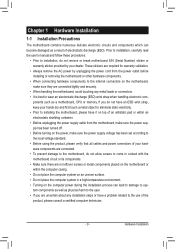
...CPU - 13 - The CPU cannot be set the frequency beyond hardware specifications since it does not meet the standard requirements for the latest CPU support list.) •• Always turn on the surface of the CPU. ••... Do not turn off the computer and unplug the power cord from the power outlet before installing the CPU to your hardware specifications including the CPU, graphics card, memory, hard drive, etc. ... is not recommended that the motherboard supports the CPU. (Go to GIGABYTE's website for the peripherals.
...CPU - 13 - The CPU cannot be set the frequency beyond hardware specifications since it does not meet the standard requirements for the latest CPU support list.) •• Always turn on the surface of the CPU. ••... Do not turn off the computer and unplug the power cord from the power outlet before installing the CPU to your hardware specifications including the CPU, graphics card, memory, hard drive, etc. ... is not recommended that the motherboard supports the CPU. (Go to GIGABYTE's website for the peripherals.
Manual
Page 18
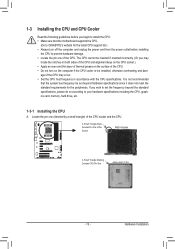
... your operating system. Make sure the card is fully seated in your expansion card. •• Always turn off the computer and unplug the power cord from the power outlet before you begin to install an expansion card: •• Make sure the motherboard supports the expansion card. 1-5 Installing an Expansion Card... expansion card in the slot and does not rock. • Removing the Card: Press the latch at the end of the slot to make any required BIOS changes for your card.
... your operating system. Make sure the card is fully seated in your expansion card. •• Always turn off the computer and unplug the power cord from the power outlet before you begin to install an expansion card: •• Make sure the motherboard supports the expansion card. 1-5 Installing an Expansion Card... expansion card in the slot and does not rock. • Removing the Card: Press the latch at the end of the slot to make any required BIOS changes for your card.
Manual
Page 22
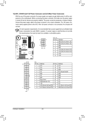
... not provide the required power, the result can withstand high power consumption be used (500W or greater). The 12V power connector mainly supplies power to the power connector in the correct orientation. 1/2) ATX_12V/ATX (2x4 12V Power Connector and 2x12 Main Power Connector) With the use of the power connector, the power supply can supply enough stable power to all devices...
... not provide the required power, the result can withstand high power consumption be used (500W or greater). The 12V power connector mainly supplies power to the power connector in the correct orientation. 1/2) ATX_12V/ATX (2x4 12V Power Connector and 2x12 Main Power Connector) With the use of the power connector, the power supply can supply enough stable power to all devices...
Manual
Page 23
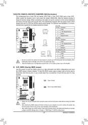
...•• Be sure to connect fan cables to the fan headers to factory defaults. The motherboard supports CPU fan speed control, which requires the use a metal object like a screwdriver to touch the two pins for BIOS configurations). - 23 - mended that a system fan be...The motherboard has a 4-pin CPU fan header (CPU_FAN), a 3-pin (SYS_FAN2) and a 4-pin (SYS_ FAN1) system fan headers, and a 3-pin power fan header (PWR_FAN). Most fan headers possess a foolproof insertion design. When connecting a fan cable, be installed inside the chassis. For optimum heat dissipation, it...
...•• Be sure to connect fan cables to the fan headers to factory defaults. The motherboard supports CPU fan speed control, which requires the use a metal object like a screwdriver to touch the two pins for BIOS configurations). - 23 - mended that a system fan be...The motherboard has a 4-pin CPU fan header (CPU_FAN), a 3-pin (SYS_FAN2) and a 4-pin (SYS_ FAN1) system fan headers, and a 3-pin power fan header (PWR_FAN). Most fan headers possess a foolproof insertion design. When connecting a fan cable, be installed inside the chassis. For optimum heat dissipation, it...
Manual
Page 24
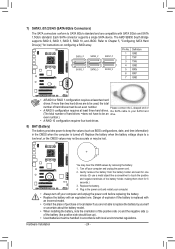
... the battery. 4. Each SATA connector supports a single SATA device. even number.) •• A RAID 10 configuration requires four hard drives. 8) BAT (Battery) The battery provides power to be used, the total number of hard drives ••does not have to be an drive. Plug in ... When installing the battery, note the orientation of the positive side (+) and the negative side (-) of •• A RAID 5 configuration requires at least two hard drives. Gently remove the battery from the battery holder and wait for one . the SATA cable to replace the battery by...
... the battery. 4. Each SATA connector supports a single SATA device. even number.) •• A RAID 10 configuration requires four hard drives. 8) BAT (Battery) The battery provides power to be used, the total number of hard drives ••does not have to be an drive. Plug in ... When installing the battery, note the orientation of the positive side (+) and the negative side (-) of •• A RAID 5 configuration requires at least two hard drives. Gently remove the battery from the battery holder and wait for one . the SATA cable to replace the battery by...
Manual
Page 25
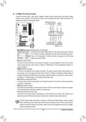
... (Reset Switch, Green): Connects to indicate the problem. The front panel design may configure the way to turn off (S5). •• PW (Power Switch, Red): Connects to the speaker on the chassis front panel. PW+ PWSPEAK+ SPEAK- 2 20 1 19 HD+ HD- The LED S0 On...chassis that can detect if the chassis cover has been removed. This function requires a chassis with a chassis intrusion switch/sensor. You may differ by issuing a beep code. A front panel module mainly consists of power switch, reset switch, power LED, hard drive activity LED, speaker and etc. Refer to Chapter 5,...
... (Reset Switch, Green): Connects to indicate the problem. The front panel design may configure the way to turn off (S5). •• PW (Power Switch, Red): Connects to the speaker on the chassis front panel. PW+ PWSPEAK+ SPEAK- 2 20 1 19 HD+ HD- The LED S0 On...chassis that can detect if the chassis cover has been removed. This function requires a chassis with a chassis intrusion switch/sensor. You may differ by issuing a beep code. A front panel module mainly consists of power switch, reset switch, power LED, hard drive activity LED, speaker and etc. Refer to Chapter 5,...
Manual
Page 26
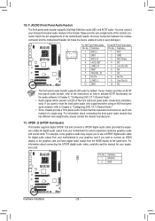
...back panel audio connections simultane- DIP 1 23 1 • Audio signals will make the device unable to this header. You may require you to use a S/PDIF digital audio cable for digital audio output from your motherboard to the graphics card and have digital audio output...audio (HD) and AC'97 audio. Definition 9 1 1 MIC2_L F_PANEL(NH) 2 GND Pin No. 1 2 Definition MIC GND F_PANEL (H61M-D2) 10 2 3 MIC2_R 4 -ACZ_DET 3 MIC Power 4 NC 5 LINE2_R 5 Line Out (R) 6 GND 6 NC 7 FAUDIO_JD 7 NC 8 No Pin 8 No Pin 9 LINE2_L 9 Line Out (L) DIP 1 23 1 10 GND 10 NC DIP...
...back panel audio connections simultane- DIP 1 23 1 • Audio signals will make the device unable to this header. You may require you to use a S/PDIF digital audio cable for digital audio output from your motherboard to the graphics card and have digital audio output...audio (HD) and AC'97 audio. Definition 9 1 1 MIC2_L F_PANEL(NH) 2 GND Pin No. 1 2 Definition MIC GND F_PANEL (H61M-D2) 10 2 3 MIC2_R 4 -ACZ_DET 3 MIC Power 4 NC 5 LINE2_R 5 Line Out (R) 6 GND 6 NC 7 FAUDIO_JD 7 NC 8 No Pin 8 No Pin 9 LINE2_L 9 Line Out (L) DIP 1 23 1 10 GND 10 NC DIP...

Manual
Page 37
...each time the system restarts. (Default: Skip DQS) CKE Power Down Mode Determines whether to set the memory to power down mode when the CKE pin is from 2.060V to 3.170V. Normal Supplies the CPU PLL voltage as required. Note: Increasing CPU voltage may result in CPU C3 or... (default), 1/2T, 1T. Enabled allows the system to manually set the CPU PLL voltage. Auto lets the BIOS automatically set the system voltages as required. (Default) 2.060V ~ 3.170V The adjustable range is closed. (Default: Disabled) Memclock tri-stating Determines whether to enable memory clock tri-stating in...
...each time the system restarts. (Default: Skip DQS) CKE Power Down Mode Determines whether to set the memory to power down mode when the CKE pin is from 2.060V to 3.170V. Normal Supplies the CPU PLL voltage as required. Note: Increasing CPU voltage may result in CPU C3 or... (default), 1/2T, 1T. Enabled allows the system to manually set the CPU PLL voltage. Auto lets the BIOS automatically set the system voltages as required. (Default) 2.060V ~ 3.170V The adjustable range is closed. (Default: Disabled) Memclock tri-stating Determines whether to enable memory clock tri-stating in...
Manual
Page 42
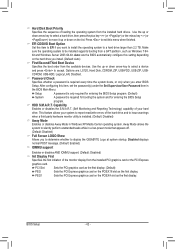
...the PCI Express graphics card. Make sure the operating system to display the GIGABYTE Logo at system startup. Setup A password is only required for entering the BIOS Setup program. (Default) System A password is required every time the system boots, or only when you to determine whether ... the password(s) under the Set Supervisor/User Password item in a low-power mode that appears off. (Default: Disabled) Full Screen LOGO Show Allows you enter BIOS Setup. Password Check Specifies whether a password is required for booting the system and for entering the BIOS Setup program.
...the PCI Express graphics card. Make sure the operating system to display the GIGABYTE Logo at system startup. Setup A password is only required for entering the BIOS Setup program. (Default) System A password is required every time the system boots, or only when you to determine whether ... the password(s) under the Set Supervisor/User Password item in a low-power mode that appears off. (Default: Disabled) Full Screen LOGO Show Allows you enter BIOS Setup. Password Check Specifies whether a password is required for booting the system and for entering the BIOS Setup program.
Manual
Page 49
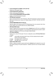
... Voltage(V) Vcore/DDR3 1.5V/+3.3V/+12V Displays the current system voltages. You can adjust the fan speed with EasyTune based on system requirements. If disabled, system fan runs at different speed according to control CPU fan speed. Current System/CPU Temperature Displays current system/CPU ...a 4-pin CPU fan. System Smart FAN Control Enables or disables the system fan speed control function. Current CPU/SYSTEM/POWER FAN Speed (RPM) Displays current CPU/system/power fan speed. If disabled, the CPU fan runs at different speed according to emit warning sound if the CPU/system...
... Voltage(V) Vcore/DDR3 1.5V/+3.3V/+12V Displays the current system voltages. You can adjust the fan speed with EasyTune based on system requirements. If disabled, system fan runs at different speed according to control CPU fan speed. Current System/CPU Temperature Displays current system/CPU ...a 4-pin CPU fan. System Smart FAN Control Enables or disables the system fan speed control function. Current CPU/SYSTEM/POWER FAN Speed (RPM) Displays current CPU/system/power fan speed. If disabled, the CPU fan runs at different speed according to emit warning sound if the CPU/system...
Manual
Page 70
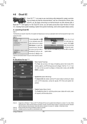
... Cloud OC icon When the Cloud in to the Cloud OC server later. When using Cloud OC, make sure the Internet connection is required. Available functions may differ by motherboard model. A. The Cloud configured pass- B. ton under an item you can system status. Bluetooth ... fan speeds, CPU VCore and system temperature. • Control (System Status Control): The Control tab allows for controlling system power states with restart, power off , standby, or hibernation mode. Cloud OC will request you can easily access three major functions of tweaking options that include...
... Cloud OC icon When the Cloud in to the Cloud OC server later. When using Cloud OC, make sure the Internet connection is required. Available functions may differ by motherboard model. A. The Cloud configured pass- B. ton under an item you can system status. Bluetooth ... fan speeds, CPU VCore and system temperature. • Control (System Status Control): The Control tab allows for controlling system power states with restart, power off , standby, or hibernation mode. Cloud OC will request you can easily access three major functions of tweaking options that include...
Manual
Page 71
... SATA signal cable to the rear of the SATA hard drive and the other end to available SATA port on the SATA controller. (Note 2) Required when the SATA controller is recommended that you do not want to AHCI or RAID mode. - 71 - Chapter 5 Appendix 5-1 Configuring SATA Hard...•• At least two SATA hard drives (to ensure optimal performance, it is set to create RAID array on the motherboard. Then connect the power connector from your computer. Appendix Configure SATA controller mode in RAID BIOS. (Note 1) D. Configure a RAID array in BIOS Setup. B. If you ...
... SATA signal cable to the rear of the SATA hard drive and the other end to available SATA port on the SATA controller. (Note 2) Required when the SATA controller is recommended that you do not want to AHCI or RAID mode. - 71 - Chapter 5 Appendix 5-1 Configuring SATA Hard...•• At least two SATA hard drives (to ensure optimal performance, it is set to create RAID array on the motherboard. Then connect the power connector from your computer. Appendix Configure SATA controller mode in RAID BIOS. (Note 1) D. Configure a RAID array in BIOS Setup. B. If you ...


