Manual
Page 1
GA-965P-DS3/S3 Intel® CoreTM 2 Extreme quad-core / CoreTM 2 Quad / Intel® CoreTM 2 Extreme dual-core / CoreTM 2 Duo / Intel® Pentium® Processor Extreme Edition / Intel&#...
GA-965P-DS3/S3 Intel® CoreTM 2 Extreme quad-core / CoreTM 2 Quad / Intel® CoreTM 2 Extreme dual-core / CoreTM 2 Duo / Intel® Pentium® Processor Extreme Edition / Intel&#...
Manual
Page 2
Motherboard GA-965P-DS3 Oct. 20, 2006 Motherboard GA-965P-DS3 Oct. 20, 2006
Motherboard GA-965P-DS3 Oct. 20, 2006 Motherboard GA-965P-DS3 Oct. 20, 2006
Manual
Page 5
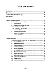
Table of Contents ItemChecklist ...7 OptionalAccessories ...7 GA-965P-DS3/S3 Motherboard Layout 8 Block Diagram ...9 Chapter 1 Hardware Installation 11 1-1 Considerations Prior to Installation 11 1-2 Feature Summary 12 1-3 Installation of ... 1-5 Installation of Expansion Cards 18 1-6 I/O Back Panel Introduction 19 1-7 Connectors Introduction 20 Chapter 2 BIOS Setup 31 The Main Menu (Example BIOS Ver.: GA-965P-DS3, F10a 32 2-1 Standard CMOS Features 34 2-2 Advanced BIOS Features 36 2-3 IntegratedPeripherals 38 2-4 Power Management Setup 41 2-5 PnP/PCI Configurations 43 2-6 PC Health...
Table of Contents ItemChecklist ...7 OptionalAccessories ...7 GA-965P-DS3/S3 Motherboard Layout 8 Block Diagram ...9 Chapter 1 Hardware Installation 11 1-1 Considerations Prior to Installation 11 1-2 Feature Summary 12 1-3 Installation of ... 1-5 Installation of Expansion Cards 18 1-6 I/O Back Panel Introduction 19 1-7 Connectors Introduction 20 Chapter 2 BIOS Setup 31 The Main Menu (Example BIOS Ver.: GA-965P-DS3, F10a 32 2-1 Standard CMOS Features 34 2-2 Advanced BIOS Features 36 2-3 IntegratedPeripherals 38 2-4 Power Management Setup 41 2-5 PnP/PCI Configurations 43 2-6 PC Health...
Manual
Page 7
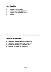
Optional Accessories Š 2 Ports USB 2.0 Cable (Part Number: 12CR1-1UB030-51/R) Š 4 Ports USB 2.0 Cable (Part Number: 12CR1-1UB030-21/R) Š S/PDIF-IN Cable (Part Number: 12CR1-1SPDIN-01R) Š e-SATA Cable (Part Number: 12CF1-3SATPW-11R) - 7 - Item Checklist IDE Cable x 1 and FDD Cable x 1 SATA 3Gb/s Cable x 4 (GA-965P-DS3 only) SATA 3Gb/s Cable x 2 (GA-965P-S3 only) I/O Shield * The items listed above are for reference only, and are subject to change without notice.
Optional Accessories Š 2 Ports USB 2.0 Cable (Part Number: 12CR1-1UB030-51/R) Š 4 Ports USB 2.0 Cable (Part Number: 12CR1-1UB030-21/R) Š S/PDIF-IN Cable (Part Number: 12CR1-1SPDIN-01R) Š e-SATA Cable (Part Number: 12CF1-3SATPW-11R) - 7 - Item Checklist IDE Cable x 1 and FDD Cable x 1 SATA 3Gb/s Cable x 4 (GA-965P-DS3 only) SATA 3Gb/s Cable x 2 (GA-965P-S3 only) I/O Shield * The items listed above are for reference only, and are subject to change without notice.
Manual
Page 8
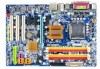
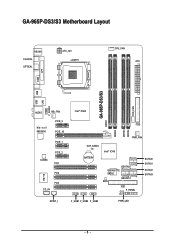
GA-965P-DS3/S3 Motherboard Layout KB_MS COAXIAL OPTICAL ATX_12V LGA775 CPU_FAN ATX COM LPT SYS_FAN GA-965P-DS3/S3 DDRII1 USB USB LAN F_AUDIO AUDIO NB_FAN Marvell 88E8056 PCIE_3 PCIE_16 PCIE_1 CODEC PCIE_2 PCI1 PCI2 IT8718 PCI3 CD_IN Intel® P965 FDD DDRII3 DDRII4 DDRII2 PWR_FAN CLR_CMOS BATTERY Intel® ICH8 GSATAII0 GIGABYTE SATA2 GSATAII1 BIOS IDE1 CI F_PANEL SATAII0 SATAII1 SATAII2 SATAII3 SPDIF_I F_USB1 F_USB2 F_USB3 PWR_LED - 8 -
GA-965P-DS3/S3 Motherboard Layout KB_MS COAXIAL OPTICAL ATX_12V LGA775 CPU_FAN ATX COM LPT SYS_FAN GA-965P-DS3/S3 DDRII1 USB USB LAN F_AUDIO AUDIO NB_FAN Marvell 88E8056 PCIE_3 PCIE_16 PCIE_1 CODEC PCIE_2 PCI1 PCI2 IT8718 PCI3 CD_IN Intel® P965 FDD DDRII3 DDRII4 DDRII2 PWR_FAN CLR_CMOS BATTERY Intel® ICH8 GSATAII0 GIGABYTE SATA2 GSATAII1 BIOS IDE1 CI F_PANEL SATAII0 SATAII1 SATAII2 SATAII3 SPDIF_I F_USB1 F_USB2 F_USB3 PWR_LED - 8 -
Manual
Page 9
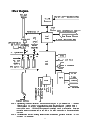
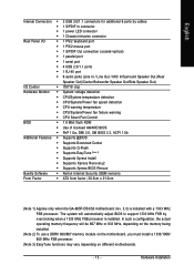
... MHz) LGA775 Processor CPU CLK+/-(333(Note 1)/266/200/133 MHz) PCI Express x16 2 SATA 3Gb/s LAN ATA 33/66/100/133 RJ45 IDE Channel GIGABYTE Marvell SATA2 88E8056 x1 PCI Express Bus x1 x1 x1 x1 PCIe CLK (100 MHz) 3 PCI Express x1 PCI Bus Host Interface DDRII 800/667... Out Surround Speaker Out Side Speaker Out MIC Line-Out Line-In SPDIF In SPDIF Out 3 PCI PCICLK (33 MHz) (Note 1) Applies only when the GA-965P-DS3/S3 motherboard (rev. 3.3) is installed. The system will be 667 MHz or 833 MHz, depending on the memory being installed. (Note 2) To use a DDRII 800...
... MHz) LGA775 Processor CPU CLK+/-(333(Note 1)/266/200/133 MHz) PCI Express x16 2 SATA 3Gb/s LAN ATA 33/66/100/133 RJ45 IDE Channel GIGABYTE Marvell SATA2 88E8056 x1 PCI Express Bus x1 x1 x1 x1 PCIe CLK (100 MHz) 3 PCI Express x1 PCI Bus Host Interface DDRII 800/667... Out Surround Speaker Out Side Speaker Out MIC Line-Out Line-In SPDIF In SPDIF Out 3 PCI PCICLK (33 MHz) (Note 1) Applies only when the GA-965P-DS3/S3 motherboard (rev. 3.3) is installed. The system will be 667 MHz or 833 MHz, depending on the memory being installed. (Note 2) To use a DDRII 800...
Manual
Page 12
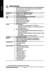
...ICH8 Southbrigde - 1 FDD connector, allowing connection of 1 FDD device - 4 SATA 3Gb/s connectors (SATAII0,1, 2, 3), allowing connection of 4 SATA 3Gb/s devices Š Onboard GIGABYTE SATA2 chip - 1 IDE connector (UDMA 33/ATA 66/ATA 100/ATA 133), allowing connection of 2 IDE devices - 2 SATA 3Gb/s connectors (GSATAII0,1), allowing connection of 2...; 1 power fan connector Š 1 northbridge fan connector Š 1 front panel connector Š 1 front audio connector Š 1 CD In connector "*" Only the GA-965P-DS3 adopts All-Solid Capacitor design. GA-965P-DS3/S3 Motherboard - 12 -
...ICH8 Southbrigde - 1 FDD connector, allowing connection of 1 FDD device - 4 SATA 3Gb/s connectors (SATAII0,1, 2, 3), allowing connection of 4 SATA 3Gb/s devices Š Onboard GIGABYTE SATA2 chip - 1 IDE connector (UDMA 33/ATA 66/ATA 100/ATA 133), allowing connection of 2 IDE devices - 2 SATA 3Gb/s connectors (GSATAII0,1), allowing connection of 2...; 1 power fan connector Š 1 northbridge fan connector Š 1 front panel connector Š 1 front audio connector Š 1 CD In connector "*" Only the GA-965P-DS3 adopts All-Solid Capacitor design. GA-965P-DS3/S3 Motherboard - 12 -
Manual
Page 13
... BIOS Rescue Bundle Software Š Norton Internet Security (OEM revision) Form Factor Š ATX form factor; 30.5cm x 21.0cm (Note 1) Applies only when the GA-965P-DS3/S3 motherboard (rev. 3.3) is installed. The system will be 667 MHz or 833 MHz, depending on the memory being installed. (Note 2) To use a DDRII 800...
... BIOS Rescue Bundle Software Š Norton Internet Security (OEM revision) Form Factor Š ATX form factor; 30.5cm x 21.0cm (Note 1) Applies only when the GA-965P-DS3/S3 motherboard (rev. 3.3) is installed. The system will be 667 MHz or 833 MHz, depending on the memory being installed. (Note 2) To use a DDRII 800...
Manual
Page 14
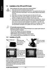
... the proper specifications, please do so according to the upright position. Fig. 2 Remove the plastic covering on the CPU prior to the CPU during installation.) GA-965P-DS3/S3 Motherboard - 14 - Avoid twisting or bending motions that has optimizations for HT Technology 1-3-1 Installation of the CPU Metal Lever Fig. 1 Gently lift the metal...
... the proper specifications, please do so according to the upright position. Fig. 2 Remove the plastic covering on the CPU prior to the CPU during installation.) GA-965P-DS3/S3 Motherboard - 14 - Avoid twisting or bending motions that has optimizations for HT Technology 1-3-1 Installation of the CPU Metal Lever Fig. 1 Gently lift the metal...
Manual
Page 16
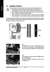
... have a foolproof insertion design. The memory capacity used can only fit in only one direction. Insert the DIMM memory module vertically into the DIMM socket. GA-965P-DS3/S3 Motherboard - 16 - Fig.2 Close the plastic clip at both edges of Memory Before installing the memory modules, please comply with each slot. Reverse the...
... have a foolproof insertion design. The memory capacity used can only fit in only one direction. Insert the DIMM memory module vertically into the DIMM socket. GA-965P-DS3/S3 Motherboard - 16 - Fig.2 Close the plastic clip at both edges of Memory Before installing the memory modules, please comply with each slot. Reverse the...
Manual
Page 17
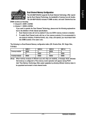
... during POST. After operating the Dual Channel Technology, the bandwidth of memory bus will not be populated and remain in dual-channel mode. - 17 - The GA-965P-DS3/S3 includes 4 DIMM sockets, and each Channel has two DIMM sockets as following explanations due to the limitation of the same color. Hardware Installation To... following : Channel 0 : DDRII1, DDRII2 Channel 1 : DDRII3, DDRII4 If you must install them into DIMM sockets of Intel chipset specifications. 1. English Dual Channel Memory Configuration The GA-965P-DS3/S3 supports the Dual Channel Technology.
... during POST. After operating the Dual Channel Technology, the bandwidth of memory bus will not be populated and remain in dual-channel mode. - 17 - The GA-965P-DS3/S3 includes 4 DIMM sockets, and each Channel has two DIMM sockets as following explanations due to the limitation of the same color. Hardware Installation To... following : Channel 0 : DDRII1, DDRII2 Channel 1 : DDRII3, DDRII4 If you must install them into DIMM sockets of Intel chipset specifications. 1. English Dual Channel Memory Configuration The GA-965P-DS3/S3 supports the Dual Channel Technology.
Manual
Page 18
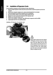
... the steps outlined below: 1. Be sure the metal contacts on the slot. Replace the screw to secure the slot bracket of expansion card from BIOS. 8. GA-965P-DS3/S3 Motherboard - 18 - Remove your computer's chassis cover. 7. Replace your computer's chassis cover, screws and slot bracket from the operating system. Installing a PCI Express x16...
... the steps outlined below: 1. Be sure the metal contacts on the slot. Replace the screw to secure the slot bracket of expansion card from BIOS. 8. GA-965P-DS3/S3 Motherboard - 18 - Remove your computer's chassis cover. 7. Replace your computer's chassis cover, screws and slot bracket from the operating system. Installing a PCI Express x16...
Manual
Page 20
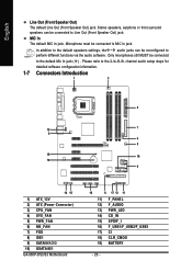
... detailed software configuration information. 1-7 Connectors Introduction 1 3 2 12 7 6 4 5 18 10 19 9 14 15 1) ATX_12V 2) ATX (Power Connector) 3) CPU_FAN 4) SYS_FAN 5) PWR_FAN 6) NB_FAN 7) FDD 8) IDE1 9) SATAII0/1/2/3 10) GSATAII0/1 GA-965P-DS3/S3 Motherboard 16 8 17 13 11 11) F_PANEL 12) F_AUDIO 13) PWR_LED 14) CD_IN 15) SPDIF_I 16) F_USB1/F_USB2/F_USB3 17) CI 18) CLR_CMOS 19...
... detailed software configuration information. 1-7 Connectors Introduction 1 3 2 12 7 6 4 5 18 10 19 9 14 15 1) ATX_12V 2) ATX (Power Connector) 3) CPU_FAN 4) SYS_FAN 5) PWR_FAN 6) NB_FAN 7) FDD 8) IDE1 9) SATAII0/1/2/3 10) GSATAII0/1 GA-965P-DS3/S3 Motherboard 16 8 17 13 11 11) F_PANEL 12) F_AUDIO 13) PWR_LED 14) CD_IN 15) SPDIF_I 16) F_USB1/F_USB2/F_USB3 17) CI 18) CLR_CMOS 19...
Manual
Page 22
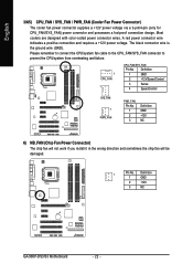
... fan cable to the CPU_FAN/SYS_FAN connector to prevent the CPU/system from overheating and failure. 1 CPU_FAN 1 CPU_FAN/SYS_FAN: Pin No. Definition 1 GND 2 +12V 3 NC GA-965P-DS3/S3 Motherboard - 22 - Definition 1 GND 2 +12V/Speed Control 3 Sense 4 Speed Control SYS_FAN 1 PWR_FAN PWR_FAN: Pin No. 1 2 3 Definition GND +12V NC 6) NB_FAN (Chip Fan Power Connector...
... fan cable to the CPU_FAN/SYS_FAN connector to prevent the CPU/system from overheating and failure. 1 CPU_FAN 1 CPU_FAN/SYS_FAN: Pin No. Definition 1 GND 2 +12V 3 NC GA-965P-DS3/S3 Motherboard - 22 - Definition 1 GND 2 +12V/Speed Control 3 Sense 4 Speed Control SYS_FAN 1 PWR_FAN PWR_FAN: Pin No. 1 2 3 Definition GND +12V NC 6) NB_FAN (Chip Fan Power Connector...
Manual
Page 24
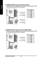
... 3Gb/s Connector, Controlled by GIGABYTE SATA2) SATA 3Gb/s can provide up to 300MB/s transfer rate. Please refer to the BIOS setting for the Serial ATA and install the proper driver in order to work properly. 7 1 GSATAII0 GSATAII1 1 7 Pin No. 1 2 3 4 5 6 7 Definition GND TXP TXN GND RXN RXP GND GA-965P-DS3/S3 Motherboard - 24 - Please...
... 3Gb/s Connector, Controlled by GIGABYTE SATA2) SATA 3Gb/s can provide up to 300MB/s transfer rate. Please refer to the BIOS setting for the Serial ATA and install the proper driver in order to work properly. 7 1 GSATAII0 GSATAII1 1 7 Pin No. 1 2 3 4 5 6 7 Definition GND TXP TXN GND RXN RXP GND GA-965P-DS3/S3 Motherboard - 24 - Please...
Manual
Page 26
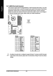
... Power 4 NC 5 Line Out (R) 6 NC 7 NC 8 No Pin 9 Line Out (L) 10 NC By default, the audio driver is configured to work or even damage it. GA-965P-DS3/S3 Motherboard - 26 - Incorrect connection between the module and connector will make the audio device unable to support HD Audio. If you connect the front...
... Power 4 NC 5 Line Out (R) 6 NC 7 NC 8 No Pin 9 Line Out (L) 10 NC By default, the audio driver is configured to work or even damage it. GA-965P-DS3/S3 Motherboard - 26 - Incorrect connection between the module and connector will make the audio device unable to support HD Audio. If you connect the front...
Manual
Page 28
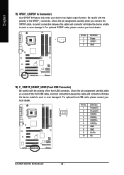
... only when your local dealer. 9 1 10 2 Pin No. 1 2 3 4 5 6 7 8 9 10 Definition Power(5V) Power(5V) USB DXUSB DyUSB DX+ USB Dy+ GND GND No Pin NC GA-965P-DS3/S3 Motherboard - 28 - Pin No. Check the pin assignment carefully while you connect the front USB cable, incorrect connection between the cable and connector will...
... only when your local dealer. 9 1 10 2 Pin No. 1 2 3 4 5 6 7 8 9 10 Definition Power(5V) Power(5V) USB DXUSB DyUSB DX+ USB Dy+ GND GND No Pin NC GA-965P-DS3/S3 Motherboard - 28 - Pin No. Check the pin assignment carefully while you connect the front USB cable, incorrect connection between the cable and connector will...
Manual
Page 30
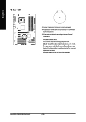
... to the manufacturer's instructions. Replace only with the same or equivalent type recommended by the manufacturer. Turn off the computer and unplug the power cord. 2. GA-965P-DS3/S3 Motherboard - 30 - If you can use a metal object to erase CMOS... 1. Re-install the battery. 4. Dispose of explosion if battery is incorrectly replaced. Plug...
... to the manufacturer's instructions. Replace only with the same or equivalent type recommended by the manufacturer. Turn off the computer and unplug the power cord. 2. GA-965P-DS3/S3 Motherboard - 30 - If you can use a metal object to erase CMOS... 1. Re-install the battery. 4. Dispose of explosion if battery is incorrectly replaced. Plug...
Manual
Page 32
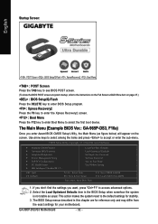
... enter the Xpress Recovery2 screen. : Boot Menu Press the F12 key to enter Boot Menu to select the first boot device. GA-965P-DS3/S3 Motherboard - 32 - The Main Menu (Example BIOS Ver.: GA-965P-DS3, F10a) Once you want, press "Ctrl+F1" to access advanced options. 2. This action makes the system reset to the default...
... enter the Xpress Recovery2 screen. : Boot Menu Press the F12 key to enter Boot Menu to select the first boot device. GA-965P-DS3/S3 Motherboard - 32 - The Main Menu (Example BIOS Ver.: GA-965P-DS3, F10a) Once you want, press "Ctrl+F1" to access advanced options. 2. This action makes the system reset to the default...
Manual
Page 34
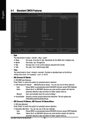
... example, 1 p.m. Manual User can use one of three methods: Auto Allows BIOS to set the access mode for faster system start up . The time is , , , . GA-965P-DS3/S3 Motherboard - 34 - English 2-1 Standard CMOS Features Date (mm:dd:yy) Time (hh:mm:ss) CMOS Setup Utility-Copyright (C) 1984-2006 Award Software Standard CMOS...
... example, 1 p.m. Manual User can use one of three methods: Auto Allows BIOS to set the access mode for faster system start up . The time is , , , . GA-965P-DS3/S3 Motherboard - 34 - English 2-1 Standard CMOS Features Date (mm:dd:yy) Time (hh:mm:ss) CMOS Setup Utility-Copyright (C) 1984-2006 Award Software Standard CMOS...


