Manual
Page 1
GA-965GM-DS2 / GA-965GM-S2 Intel® CoreTM 2 Extreme quad-core / CoreTM 2 Quad / Intel® CoreTM 2 Extreme dual-core / CoreTM 2 Duo / Intel® Pentium® Processor Extreme Edition / Intel® ...
GA-965GM-DS2 / GA-965GM-S2 Intel® CoreTM 2 Extreme quad-core / CoreTM 2 Quad / Intel® CoreTM 2 Extreme dual-core / CoreTM 2 Duo / Intel® Pentium® Processor Extreme Edition / Intel® ...
Manual
Page 2
Motherboard GA-965GM-DS2 / GA-965GM-S2 Oct. 1, 2006 Motherboard GA-965GM-DS2 / GA-965GM-S2 Oct. 1, 2006
Motherboard GA-965GM-DS2 / GA-965GM-S2 Oct. 1, 2006 Motherboard GA-965GM-DS2 / GA-965GM-S2 Oct. 1, 2006
Manual
Page 4
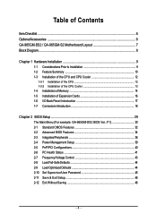
Table of Contents ItemChecklist ...6 OptionalAccessories ...6 GA-965GM-DS2 / GA-965GM-S2 Motherboard Layout 7 Block Diagram ...8 Chapter 1 Hardware Installation 9 1-1 Considerations Prior to Installation 9 1-2 Feature Summary 10 1-3 Installation of the ... 1-5 Installation of Expansion Cards 16 1-6 I/O Back Panel Introduction 17 1-7 Connectors Introduction 18 Chapter 2 BIOS Setup 29 The Main Menu (For example: GA-965GM-DS2 BIOS Ver.: F1 30 2-1 Standard CMOS Features 32 2-2 Advanced BIOS Features 34 2-3 IntegratedPeripherals 36 2-4 Power Management Setup 39 2-5 PnP/PCI Configurations...
Table of Contents ItemChecklist ...6 OptionalAccessories ...6 GA-965GM-DS2 / GA-965GM-S2 Motherboard Layout 7 Block Diagram ...8 Chapter 1 Hardware Installation 9 1-1 Considerations Prior to Installation 9 1-2 Feature Summary 10 1-3 Installation of the ... 1-5 Installation of Expansion Cards 16 1-6 I/O Back Panel Introduction 17 1-7 Connectors Introduction 18 Chapter 2 BIOS Setup 29 The Main Menu (For example: GA-965GM-DS2 BIOS Ver.: F1 30 2-1 Standard CMOS Features 32 2-2 Advanced BIOS Features 34 2-3 IntegratedPeripherals 36 2-4 Power Management Setup 39 2-5 PnP/PCI Configurations...
Manual
Page 7
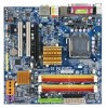
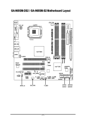
GA-965GM-DS2 / GA-965GM-S2 Motherboard Layout KB_MS ATX_12V LGA775 CPU_FAN ATX FDD IT8718 COMA GA-965GM-DS2 / GA-965GM-S2 DDRII1 LPT VGA USB_1394 USB_LAN Intel® G965 AUDIO F_AUDIO Marvell 88E8056 PCIE_16 PCI1 BIOS PCI2 Intel® ICH8 IDE GIGABYTE SATA2 CD_IN CODEC PCIE_1 CI CLR_CMOS BATTERY COMB F1_1394 F2_1394 F_USB2 F_USB3 SATAII2 SATAII3 SPDIF_IO SYS _FAN F_USB1 SATAII0 GSATAII0 SATAII1 GSATAII1 DDRII2 DDRII3 DDRII4 PWR_LED F_PANEL - 7 -
GA-965GM-DS2 / GA-965GM-S2 Motherboard Layout KB_MS ATX_12V LGA775 CPU_FAN ATX FDD IT8718 COMA GA-965GM-DS2 / GA-965GM-S2 DDRII1 LPT VGA USB_1394 USB_LAN Intel® G965 AUDIO F_AUDIO Marvell 88E8056 PCIE_16 PCI1 BIOS PCI2 Intel® ICH8 IDE GIGABYTE SATA2 CD_IN CODEC PCIE_1 CI CLR_CMOS BATTERY COMB F1_1394 F2_1394 F_USB2 F_USB3 SATAII2 SATAII3 SPDIF_IO SYS _FAN F_USB1 SATAII0 GSATAII0 SATAII1 GSATAII1 DDRII2 DDRII3 DDRII4 PWR_LED F_PANEL - 7 -
Manual
Page 10
...ICH8 Southbrigde - 1 FDD connector, allowing connection of 1 FDD device - 4 SATA 3Gb/s connectors (SATAII0,1, 2, 3), allowing connection of 4 SATA 3Gb/s devices Š Onboard GIGABYTE SATA2 chip - 1 IDE connector (ATA-33/66/100/133), allowing connection of 2 IDE devices - 2 SATA 3Gb/s connectors (GSATAII0,1), allowing connection of 2 SATA 3Gb/s ... system fan connector Š 1 front panel connector Š 1 front audio connector Š 1 CD In connector Š 1 power LED connector "*" Only the GA-965GM-DS2 adopts All-Solid Capacitor design. GA-965GM-(D)S2 Motherboard - 10 -
...ICH8 Southbrigde - 1 FDD connector, allowing connection of 1 FDD device - 4 SATA 3Gb/s connectors (SATAII0,1, 2, 3), allowing connection of 4 SATA 3Gb/s devices Š Onboard GIGABYTE SATA2 chip - 1 IDE connector (ATA-33/66/100/133), allowing connection of 2 IDE devices - 2 SATA 3Gb/s connectors (GSATAII0,1), allowing connection of 2 SATA 3Gb/s ... system fan connector Š 1 front panel connector Š 1 front audio connector Š 1 CD In connector Š 1 power LED connector "*" Only the GA-965GM-DS2 adopts All-Solid Capacitor design. GA-965GM-(D)S2 Motherboard - 10 -

Manual
Page 12
... : Enabling the functionality of the CPU may occur. 5. Fig. 3 Notice the small gold colored triangle located on the CPU prior to the CPU during installation.) GA-965GM-(D)S2 Motherboard - 12 - Please make sure the heatsink is properly inserted, please replace the plastic covering and push the metal lever back into the socket in...
... : Enabling the functionality of the CPU may occur. 5. Fig. 3 Notice the small gold colored triangle located on the CPU prior to the CPU during installation.) GA-965GM-(D)S2 Motherboard - 12 - Please make sure the heatsink is properly inserted, please replace the plastic covering and push the metal lever back into the socket in...

Manual
Page 14
... the DIMM memory module vertically into the DIMM socket. Notch DDRII Fig.1 The DIMM socket has a notch, so the DIMM memory module can be used. 2. GA-965GM-(D)S2 Motherboard - 14 - Before installing or removing memory modules, please make sure that the memory used can be installed in one direction. Memory modules are unable...
... the DIMM memory module vertically into the DIMM socket. Notch DDRII Fig.1 The DIMM socket has a notch, so the DIMM memory module can be used. 2. GA-965GM-(D)S2 Motherboard - 14 - Before installing or removing memory modules, please make sure that the memory used can be installed in one direction. Memory modules are unable...
Manual
Page 15
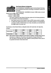
Hardware Installation The GA-965GM-DS2 / GA-965GM-S2 includes 4 DIMM sockets, and each Channel has two DIMM sockets as following: Channel 0 : DDRII1, DDRII2 Channel 1 : DDRII3, DDRII4 If you must install them into DIMM ... Memory Technology offers easier upgrades by allowing different memory sizes to Flex memory mode operation will appear during POST. English Dual Channel Memory Configuration The GA-965GM-DS2 / GA-965GM-S2 supports the Dual Channel Technology. Dual Channel mode will double. To enable Dual Channel mode with two or four memory modules (it is a Dual...
Hardware Installation The GA-965GM-DS2 / GA-965GM-S2 includes 4 DIMM sockets, and each Channel has two DIMM sockets as following: Channel 0 : DDRII1, DDRII2 Channel 1 : DDRII3, DDRII4 If you must install them into DIMM ... Memory Technology offers easier upgrades by allowing different memory sizes to Flex memory mode operation will appear during POST. English Dual Channel Memory Configuration The GA-965GM-DS2 / GA-965GM-S2 supports the Dual Channel Technology. Dual Channel mode will double. To enable Dual Channel mode with two or four memory modules (it is a Dual...

Manual
Page 16
... the small whitedrawable bar at the end of the PCI Express x16 slot when you try to secure the slot bracket of the expansion card. 6. GA-965GM-(D)S2 Motherboard - 16 - English 1-5 Installation of Expansion Cards You can also press the latch on the back of the drawable bar as the picture to the...
... the small whitedrawable bar at the end of the PCI Express x16 slot when you try to secure the slot bracket of the expansion card. 6. GA-965GM-(D)S2 Motherboard - 16 - English 1-5 Installation of Expansion Cards You can also press the latch on the back of the drawable bar as the picture to the...

Manual
Page 18
... 15 19 14 78 11) F_AUDIO 12) CD_IN 13) SPDIF_IO 14) F_USB1 / F_USB2 / F_USB3 15) F1_1394 / F2_1394 16) COMB 17) CI 18) CLR_CMOS 19) BATTERY GA-965GM-(D)S2 Motherboard - 18 - Stereo speakers, earphone or front surround speakers can be connected to Line Out (Front Speaker Out) jack. In addition to the default speakers...
... 15 19 14 78 11) F_AUDIO 12) CD_IN 13) SPDIF_IO 14) F_USB1 / F_USB2 / F_USB3 15) F1_1394 / F2_1394 16) COMB 17) CI 18) CLR_CMOS 19) BATTERY GA-965GM-(D)S2 Motherboard - 18 - Stereo speakers, earphone or front surround speakers can be connected to Line Out (Front Speaker Out) jack. In addition to the default speakers...
Manual
Page 20
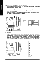
... Slave (for information on the IDE device). Before attaching the IDE cable, please take note of the foolproof groove in the IDE connector. 40 39 GA-965GM-(D)S2 Motherboard - 20 - 2 1 Remember to connect the CPU/system fan cable to the CPU_FAN/SYS_FAN connector to the computer via a 4-pin power connector and possesses a foolproof...
... Slave (for information on the IDE device). Before attaching the IDE cable, please take note of the foolproof groove in the IDE connector. 40 39 GA-965GM-(D)S2 Motherboard - 20 - 2 1 Remember to connect the CPU/system fan cable to the CPU_FAN/SYS_FAN connector to the computer via a 4-pin power connector and possesses a foolproof...
Manual
Page 22
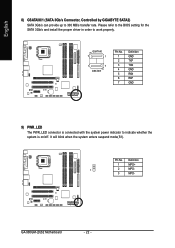
.../s and install the proper driver in order to 300 MB/s transfer rate. Pin No. English 8) GSATAII0/1 (SATA 3Gb/s Connector, Controlled by GIGABYTE SATA2) SATA 3Gb/s can provide up to work properly. GA-965GM-(D)S2 Motherboard - 22 - GSATAII0 7 1 1 7 GSATAII1 Pin No. 1 2 3 4 5 6 7 Definition GND TXP TXN GND RXN RXP GND 9) PWR_LED The PWR_LED connector is connected...
.../s and install the proper driver in order to 300 MB/s transfer rate. Pin No. English 8) GSATAII0/1 (SATA 3Gb/s Connector, Controlled by GIGABYTE SATA2) SATA 3Gb/s can provide up to work properly. GA-965GM-(D)S2 Motherboard - 22 - GSATAII0 7 1 1 7 GSATAII1 Pin No. 1 2 3 4 5 6 7 Definition GND TXP TXN GND RXN RXP GND 9) PWR_LED The PWR_LED connector is connected...

Manual
Page 24
... is configured to work or even damage it. Incorrect connection between the module and connector will make the audio device unable to support HD Audio. GA-965GM-(D)S2 Motherboard - 24 - For optional front panel audio module, please contact your chassis manufacturer. 10 9 2 1 HD Audio: Pin No. 1 2 3 4 5 6 7 8 9 10 Definition MIC2_L GND MIC2_R -ACZ_DET LINE2_R...
... is configured to work or even damage it. Incorrect connection between the module and connector will make the audio device unable to support HD Audio. GA-965GM-(D)S2 Motherboard - 24 - For optional front panel audio module, please contact your chassis manufacturer. 10 9 2 1 HD Audio: Pin No. 1 2 3 4 5 6 7 8 9 10 Definition MIC2_L GND MIC2_R -ACZ_DET LINE2_R...
Manual
Page 26
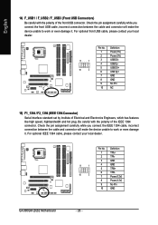
... optional front USB cable, please contact your local dealer. 9 1 10 2 Pin No. 1 2 3 4 5 6 7 8 9 10 Definition TPA+ TPAGND GND TPB+ TPBPower (12V) Power (12V) No Pin GND GA-965GM-(D)S2 Motherboard - 26 - Be careful with the polarity of the front USB connector. For optional IEEE 1394 cable, please contact your local dealer. 9 1 10 2 Pin No...
... optional front USB cable, please contact your local dealer. 9 1 10 2 Pin No. 1 2 3 4 5 6 7 8 9 10 Definition TPA+ TPAGND GND TPB+ TPBPower (12V) Power (12V) No Pin GND GA-965GM-(D)S2 Motherboard - 26 - Be careful with the polarity of the front USB connector. For optional IEEE 1394 cable, please contact your local dealer. 9 1 10 2 Pin No...
Manual
Page 28
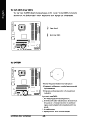
.... English 18) CLR_CMOS (Clear CMOS) You may clear the CMOS data to its default values by the manufacturer. Open: Normal Short: Clear CMOS 19) BATTERY GA-965GM-(D)S2 Motherboard Danger of used batteries according to connect the positive and negative pins in and turn on the computer. - 28 - Default doesn't include the jumper...
.... English 18) CLR_CMOS (Clear CMOS) You may clear the CMOS data to its default values by the manufacturer. Open: Normal Short: Clear CMOS 19) BATTERY GA-965GM-(D)S2 Motherboard Danger of used batteries according to connect the positive and negative pins in and turn on the computer. - 28 - Default doesn't include the jumper...

Manual
Page 30
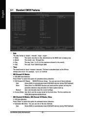
... LS120 Hard Disk CDROM ZIP USB-FDD USB-ZIP USB-CDROM USB-HDD LAN KL:Move Enter :Accept ESC:Exit The Main Menu (For example: GA-965GM-DS2 BIOS Ver.: F1) Once you want, press "Ctrl+F1" to accept. Select the Load Optimized Defaults item in this menu. English : Boot Menu... Type... 1. This action makes the system reset to exit this chapter are for reference only and may differ from the exact settings for stability. 3. GA-965GM-(D)S2 Motherboard - 30 - The BIOS Setup menus described in the BIOS Setup when somehow the system is not stable as figure below) will appear on cards...
... LS120 Hard Disk CDROM ZIP USB-FDD USB-ZIP USB-CDROM USB-HDD LAN KL:Move Enter :Accept ESC:Exit The Main Menu (For example: GA-965GM-DS2 BIOS Ver.: F1) Once you want, press "Ctrl+F1" to accept. Select the Load Optimized Defaults item in this menu. English : Boot Menu... Type... 1. This action makes the system reset to exit this chapter are for reference only and may differ from the exact settings for stability. 3. GA-965GM-(D)S2 Motherboard - 30 - The BIOS Setup menus described in the BIOS Setup when somehow the system is not stable as figure below) will appear on cards...
Manual
Page 32
.../Large/Auto(default:Auto) IDE Channel 2/3 Master, IDE Channel 4/5 Master, Slave IDE Auto-Detection Press "Enter" to automatically detect IDE/SATA devices during POST(default) GA-965GM-(D)S2 Motherboard - 32 - Extended IDE Drive. IDE Channel 0/1 Master IDE HDD Auto-Detection Press "Enter" to select this if no IDE/SATA devices are used and...
.../Large/Auto(default:Auto) IDE Channel 2/3 Master, IDE Channel 4/5 Master, Slave IDE Auto-Detection Press "Enter" to automatically detect IDE/SATA devices during POST(default) GA-965GM-(D)S2 Motherboard - 32 - Extended IDE Drive. IDE Channel 0/1 Master IDE HDD Auto-Detection Press "Enter" to select this if no IDE/SATA devices are used and...

Manual
Page 34
... your boot device priority by USB-HDD. LS120 Select your boot device priority by LS120. USB-ZIP Select your boot device priority by USB-ZIP. GA-965GM-(D)S2 Motherboard - 34 -
... your boot device priority by USB-HDD. LS120 Select your boot device priority by LS120. USB-ZIP Select your boot device priority by USB-ZIP. GA-965GM-(D)S2 Motherboard - 34 -

Manual
Page 36
... drives during POST. Enabled Disabled BIOS will scan all USB storage devices. (Default value) Disable this function if you are not using onboard USB 2.0 feature. GA-965GM-(D)S2 Motherboard - 36 - USB Keyboard Support Enabled Enable USB Keyboard Support. Azalia Codec Auto Auto detect Azalia audio function. (Default value) Disabled Disable Azalia audio function...
... drives during POST. Enabled Disabled BIOS will scan all USB storage devices. (Default value) Disable this function if you are not using onboard USB 2.0 feature. GA-965GM-(D)S2 Motherboard - 36 - USB Keyboard Support Enabled Enable USB Keyboard Support. Azalia Codec Auto Auto detect Azalia audio function. (Default value) Disabled Disable Azalia audio function...
Manual
Page 38
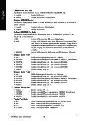
... plug. Onboard Serial Port 1 Auto BIOS will automatically setup the port 2 address. Enable onboard Serial port 2 and address is 3BC/IRQ7. GA-965GM-(D)S2 Motherboard - 38 - IDE Set the SATA channel to IDE mode.(Default value) AHCI Set the SATA channel to IDE mode. Onboard Serial Port...LPT port. English OnBoard LAN Boot ROM This function decide whether to enable or disable the SATA/IDE ports controlled by the GIGABYTE SATA2 controller. Enabled Enable this function.(Default value) Disabled Disable this function. OnBoard SATA/IDE Ctrl Mode This function allows ...
... plug. Onboard Serial Port 1 Auto BIOS will automatically setup the port 2 address. Enable onboard Serial port 2 and address is 3BC/IRQ7. GA-965GM-(D)S2 Motherboard - 38 - IDE Set the SATA channel to IDE mode.(Default value) AHCI Set the SATA channel to IDE mode. Onboard Serial Port...LPT port. English OnBoard LAN Boot ROM This function decide whether to enable or disable the SATA/IDE ports controlled by the GIGABYTE SATA2 controller. Enabled Enable this function.(Default value) Disabled Disable this function. OnBoard SATA/IDE Ctrl Mode This function allows ...


