Manual
Page 4
...GA-965GM-S2 Motherboard Layout 7 Block Diagram ...8 Chapter 1 Hardware Installation 9 1-1 Considerations Prior to Installation 9 1-2 Feature Summary 10 1-3 Installation of the CPU and CPU Cooler 12 1-3-1 Installation of the CPU 12 1-3-2 Installation of the CPU Cooler 13 1-4 Installation of Memory 14 1-5 Installation of Expansion Cards 16 1-6 I/O Back Panel Introduction 17 1-7 Connectors Introduction 18 Chapter 2 BIOS... Setup 29 The Main Menu (For example: GA-965GM-DS2 BIOS Ver.: F1 30 2-1 Standard CMOS Features 32 2-2 Advanced BIOS Features 34 2-3 ...
...GA-965GM-S2 Motherboard Layout 7 Block Diagram ...8 Chapter 1 Hardware Installation 9 1-1 Considerations Prior to Installation 9 1-2 Feature Summary 10 1-3 Installation of the CPU and CPU Cooler 12 1-3-1 Installation of the CPU 12 1-3-2 Installation of the CPU Cooler 13 1-4 Installation of Memory 14 1-5 Installation of Expansion Cards 16 1-6 I/O Back Panel Introduction 17 1-7 Connectors Introduction 18 Chapter 2 BIOS... Setup 29 The Main Menu (For example: GA-965GM-DS2 BIOS Ver.: F1 30 2-1 Standard CMOS Features 32 2-2 Advanced BIOS Features 34 2-3 ...

Manual
Page 5
Chapter 3 Install Drivers 47 3-1 Install Chipset Drivers 47 3-2 SoftwareApplications 48 3-3 Driver CD Information 48 3-4 Hardware Information 49 3-5 Contact Us ...49 Chapter 4 Appendix 51 4-1 Unique Software Utilities 51 4-1-1 EasyTune 5 Introduction 51 4-1-2 Xpress Recovery2 Introduction 52 4-1-3 Flash BIOS Method Introduction 54 4-1-4 Configuring SATA Hard Drive(s) (Controller: GIGABYTE SATA2 63 4-1-5 2- / 4- / 6- / 8- Channel Audio Function Introduction 76 4-2 Troubleshooting 81 - 5 -
Chapter 3 Install Drivers 47 3-1 Install Chipset Drivers 47 3-2 SoftwareApplications 48 3-3 Driver CD Information 48 3-4 Hardware Information 49 3-5 Contact Us ...49 Chapter 4 Appendix 51 4-1 Unique Software Utilities 51 4-1-1 EasyTune 5 Introduction 51 4-1-2 Xpress Recovery2 Introduction 52 4-1-3 Flash BIOS Method Introduction 54 4-1-4 Configuring SATA Hard Drive(s) (Controller: GIGABYTE SATA2 63 4-1-5 2- / 4- / 6- / 8- Channel Audio Function Introduction 76 4-2 Troubleshooting 81 - 5 -
Manual
Page 7
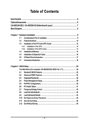
GA-965GM-DS2 / GA-965GM-S2 Motherboard Layout KB_MS ATX_12V LGA775 CPU_FAN ATX FDD IT8718 COMA GA-965GM-DS2 / GA-965GM-S2 DDRII1 LPT VGA USB_1394 USB_LAN Intel® G965 AUDIO F_AUDIO Marvell 88E8056 PCIE_16 PCI1 BIOS PCI2 Intel® ICH8 IDE GIGABYTE SATA2 CD_IN CODEC PCIE_1 CI CLR_CMOS BATTERY COMB F1_1394 F2_1394 F_USB2 F_USB3 SATAII2 SATAII3 SPDIF_IO SYS _FAN F_USB1 SATAII0 GSATAII0 SATAII1 GSATAII1 DDRII2 DDRII3 DDRII4 PWR_LED F_PANEL - 7 -
GA-965GM-DS2 / GA-965GM-S2 Motherboard Layout KB_MS ATX_12V LGA775 CPU_FAN ATX FDD IT8718 COMA GA-965GM-DS2 / GA-965GM-S2 DDRII1 LPT VGA USB_1394 USB_LAN Intel® G965 AUDIO F_AUDIO Marvell 88E8056 PCIE_16 PCI1 BIOS PCI2 Intel® ICH8 IDE GIGABYTE SATA2 CD_IN CODEC PCIE_1 CI CLR_CMOS BATTERY COMB F1_1394 F2_1394 F_USB2 F_USB3 SATAII2 SATAII3 SPDIF_IO SYS _FAN F_USB1 SATAII0 GSATAII0 SATAII1 GSATAII1 DDRII2 DDRII3 DDRII4 PWR_LED F_PANEL - 7 -

Manual
Page 8
... CLK (100 MHz) LGA775 Processor CPU CLK+/-(266/200/133 MHz) VGA PCI Express x16 2 SATA 3Gb/s LAN ATA-33/66/100/133 IDE Channel GIGABYTE RJ45 Marvell SATA2 88E8056 PCI Express Bus x 1 x1 x1 PCIe CLK (100 MHz) 1 PCI Express x1 PCI Bus TSB43AB23 Host Interface DDRII 800/667/533... MHz DIMM(Note) Intel® G965 Dual Channel Memory GMCH CLK (266/200/133 MHz) Intel® ICH8 CODEC BIOS 4 SATA 3Gb/s IT8718 LPT Floppy COM Ports PS/2 KB/Mouse 3 IEEE 1394a Surround Speaker Out Center/Subwoofer Speaker Out Side Speaker Out MIC Line-Out...
... CLK (100 MHz) LGA775 Processor CPU CLK+/-(266/200/133 MHz) VGA PCI Express x16 2 SATA 3Gb/s LAN ATA-33/66/100/133 IDE Channel GIGABYTE RJ45 Marvell SATA2 88E8056 PCI Express Bus x 1 x1 x1 PCIe CLK (100 MHz) 1 PCI Express x1 PCI Bus TSB43AB23 Host Interface DDRII 800/667/533... MHz DIMM(Note) Intel® G965 Dual Channel Memory GMCH CLK (266/200/133 MHz) Intel® ICH8 CODEC BIOS 4 SATA 3Gb/s IT8718 LPT Floppy COM Ports PS/2 KB/Mouse 3 IEEE 1394a Surround Speaker Out Center/Subwoofer Speaker Out Side Speaker Out MIC Line-Out...

Manual
Page 11
...CPU / System fan failure warning Š CPU Smart Fan Control BIOS Š 1 8 Mbit flash ROM Š Use of licensed AWARD BIOS Š PnP 1.0a, DMI 2.0, SM BIOS 2.3, ACPI 1.0b Additional Features Š Supports @BIOS Š Supports Download Center Š Supports Q-Flash Š ...Supports EasyTune(only supports Hardware Monitor function) (Note 2) Š Supports Xpress Install Š Supports Xpress Recovery2 Š Supports Xpress BIOS Rescue Bundle Software Š Norton Internet Security (OEM version) Form Factor Š Micro ATX form factor; 24.4cm x 24.4cm (Note...
...CPU / System fan failure warning Š CPU Smart Fan Control BIOS Š 1 8 Mbit flash ROM Š Use of licensed AWARD BIOS Š PnP 1.0a, DMI 2.0, SM BIOS 2.3, ACPI 1.0b Additional Features Š Supports @BIOS Š Supports Download Center Š Supports Q-Flash Š ...Supports EasyTune(only supports Hardware Monitor function) (Note 2) Š Supports Xpress Install Š Supports Xpress Recovery2 Š Supports Xpress BIOS Rescue Bundle Software Š Norton Internet Security (OEM version) Form Factor Š Micro ATX form factor; 24.4cm x 24.4cm (Note...

Manual
Page 12
If you install the CPU in accordance with HT Technology - BIOS: A BIOS that supports HT Technology - Fig. 3 Notice the small gold colored triangle located on the CPU socket. If you wish to set the frequency beyond hardware ... for HT Technology 1-3-1 Installation of the CPU Metal Lever Fig. 1 Gently lift the metal lever located on the CPU prior to the CPU during installation.) GA-965GM-(D)S2 Motherboard - 12 - Please add an even layer of the CPU. If this occurs, please change the insert direction of the CPU. 3. Fig. 2 Remove the plastic...
If you install the CPU in accordance with HT Technology - BIOS: A BIOS that supports HT Technology - Fig. 3 Notice the small gold colored triangle located on the CPU socket. If you wish to set the frequency beyond hardware ... for HT Technology 1-3-1 Installation of the CPU Metal Lever Fig. 1 Gently lift the metal lever located on the CPU prior to the CPU during installation.) GA-965GM-(D)S2 Motherboard - 12 - Please add an even layer of the CPU. If this occurs, please change the insert direction of the CPU. 3. Fig. 2 Remove the plastic...

Manual
Page 14
... socket. English 1-4 Installation of Memory Before installing the memory modules, please comply with each slot. The motherboard supports DDRII memory modules, whereby BIOS will automatically detect memory capacity and specifications. GA-965GM-(D)S2 Motherboard - 14 - Then push it down. Fig.2 Close the plastic clip at both edges of similar capacity, specifications and brand be...
... socket. English 1-4 Installation of Memory Before installing the memory modules, please comply with each slot. The motherboard supports DDRII memory modules, whereby BIOS will automatically detect memory capacity and specifications. GA-965GM-(D)S2 Motherboard - 14 - Then push it down. Fig.2 Close the plastic clip at both edges of similar capacity, specifications and brand be...

Manual
Page 16
...slot bracket from the computer. 3. Install related driver from BIOS. 8. Make sure your computer's chassis cover. 7. To install a VGA card or to install/ uninstall the VGA card. Press the expansion card firmly into the computer. 2. Power on the slot. GA-965GM-(D)S2 Motherboard - 16 - Be sure the metal contacts on... the back of the drawable bar as the picture to the onboard PCI Express x16 slot and press firmly down on the computer, if necessary, setup BIOS utility of expansion card from the ...
...slot bracket from the computer. 3. Install related driver from BIOS. 8. Make sure your computer's chassis cover. 7. To install a VGA card or to install/ uninstall the VGA card. Press the expansion card firmly into the computer. 2. Power on the slot. GA-965GM-(D)S2 Motherboard - 16 - Be sure the metal contacts on... the back of the drawable bar as the picture to the onboard PCI Express x16 slot and press firmly down on the computer, if necessary, setup BIOS utility of expansion card from the ...

Manual
Page 21
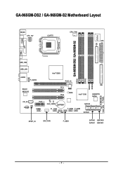
... are: 360 KB, 720 KB, 1.2 MB, 1.44 MB and 2.88 MB. The types of the cable connects to the FDD drive. Please refer to the BIOS setting for the SATA 3Gb/s and install the proper driver in the FDD connector. 34 33 2 1 7) SATAII0 / 1 / 2 / 3 (SATA 3Gb/s Connector, Controlled by Intel ICH8) SATA...
... are: 360 KB, 720 KB, 1.2 MB, 1.44 MB and 2.88 MB. The types of the cable connects to the FDD drive. Please refer to the BIOS setting for the SATA 3Gb/s and install the proper driver in the FDD connector. 34 33 2 1 7) SATAII0 / 1 / 2 / 3 (SATA 3Gb/s Connector, Controlled by Intel ICH8) SATA...
Manual
Page 22
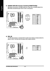
Please refer to the BIOS setting for the SATA 3Gb/s and install the proper driver in order to indicate whether the system is on/off. GSATAII0 7 1 1 7 GSATAII1 Pin No. 1 2 3 4 5 6 7 Definition ... 9) PWR_LED The PWR_LED connector is connected with the system power indicator to work properly. Pin No. Definition 1 MPD+ 1 2 MPD- 3 MPD- GA-965GM-(D)S2 Motherboard - 22 - It will blink when the system enters suspend mode(S1). English 8) GSATAII0/1 (SATA 3Gb/s Connector, Controlled by GIGABYTE SATA2) SATA 3Gb/s can provide up to 300 MB/s transfer rate.
Please refer to the BIOS setting for the SATA 3Gb/s and install the proper driver in order to indicate whether the system is on/off. GSATAII0 7 1 1 7 GSATAII1 Pin No. 1 2 3 4 5 6 7 Definition ... 9) PWR_LED The PWR_LED connector is connected with the system power indicator to work properly. Pin No. Definition 1 MPD+ 1 2 MPD- 3 MPD- GA-965GM-(D)S2 Motherboard - 22 - It will blink when the system enters suspend mode(S1). English 8) GSATAII0/1 (SATA 3Gb/s Connector, Controlled by GIGABYTE SATA2) SATA 3Gb/s can provide up to 300 MB/s transfer rate.

Manual
Page 27
Pin No. Definition 1 1 Signal 2 GND - 27 - Hardware Installation Check the pin assignments while you connect the COMB cable. Please contact your nearest dealer for optional COMB cable. 2 10 1 9 Pin No. 1 2 3 4 5 6 7 8 9 10 Definition NDCDBNSINB NSOUTB NDTRBGND NDSRBNRTSBNCTSBNRIBNo Pin 17) CI (Chassis Intrusion, Case Open) This 2-pin connector allows your system to detect if the chassis cover is removed. You can check the "Case Opened" status in BIOS Setup. English 16) COMB (COMB Connector) Be careful with the polarity of the COMB connector.
Pin No. Definition 1 1 Signal 2 GND - 27 - Hardware Installation Check the pin assignments while you connect the COMB cable. Please contact your nearest dealer for optional COMB cable. 2 10 1 9 Pin No. 1 2 3 4 5 6 7 8 9 10 Definition NDCDBNSINB NSOUTB NDTRBGND NDSRBNRTSBNCTSBNRIBNo Pin 17) CI (Chassis Intrusion, Case Open) This 2-pin connector allows your system to detect if the chassis cover is removed. You can check the "Case Opened" status in BIOS Setup. English 16) COMB (COMB Connector) Be careful with the polarity of the COMB connector.
Manual
Page 29
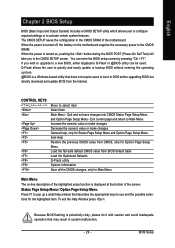
... Windows-based utility that describes the appropriate keys to activate certain system features. Exit current page and return to DOS before upgrading BIOS but directly download and update BIOS from BIOS default table Load the Optimized Defaults Q-Flash utility System Information Save all the CMOS changes, only for the highlighted item. When... settings or to use and the possible selections for Main Menu Main Menu The on the motherboard supplies the necessary power to a new BIOS, either Gigabyte's Q-Flash or @BIOS utility can enter the BIOS setup screen by pressing "Ctrl + F1".
... Windows-based utility that describes the appropriate keys to activate certain system features. Exit current page and return to DOS before upgrading BIOS but directly download and update BIOS from BIOS default table Load the Optimized Defaults Q-Flash utility System Information Save all the CMOS changes, only for the highlighted item. When... settings or to use and the possible selections for Main Menu Main Menu The on the motherboard supplies the necessary power to a new BIOS, either Gigabyte's Q-Flash or @BIOS utility can enter the BIOS setup screen by pressing "Ctrl + F1".

Manual
Page 30
... to exit this chapter are for reference only and may differ from the exact settings for your motherboard. GA-965GM-(D)S2 Motherboard - 30 - Intel G965 BIOS for stability. 3. If you don't find the settings you enter Award BIOS CMOS Setup Utility, the Main Menu (as usual. This action makes the system reset to the default... LS120 Hard Disk CDROM ZIP USB-FDD USB-ZIP USB-CDROM USB-HDD LAN KL:Move Enter :Accept ESC:Exit The Main Menu (For example: GA-965GM-DS2 BIOS Ver.: F1) Once you want, press "Ctrl+F1" to accept. Select the Load Optimized Defaults item in this menu.
... to exit this chapter are for reference only and may differ from the exact settings for your motherboard. GA-965GM-(D)S2 Motherboard - 30 - Intel G965 BIOS for stability. 3. If you don't find the settings you enter Award BIOS CMOS Setup Utility, the Main Menu (as usual. This action makes the system reset to the default... LS120 Hard Disk CDROM ZIP USB-FDD USB-ZIP USB-CDROM USB-HDD LAN KL:Move Enter :Accept ESC:Exit The Main Menu (For example: GA-965GM-DS2 BIOS Ver.: F1) Once you want, press "Ctrl+F1" to accept. Select the Load Optimized Defaults item in this menu.

Manual
Page 31
...the system parameters which the system would be in best performance configuration. „ Set Supervisor Password Change, set , or disable password. BIOS Setup It allows you to limit access to the system. „ Save & Exit Setup Save CMOS value settings to Setup. „... Change, set , or disable password. English „ Standard CMOS Features This setup page includes all the items in standard compatible BIOS. „ Advanced BIOS Features This setup page includes all the items of Award special enhanced features. „ Integrated Peripherals This setup page includes all onboard...
...the system parameters which the system would be in best performance configuration. „ Set Supervisor Password Change, set , or disable password. BIOS Setup It allows you to limit access to the system. „ Save & Exit Setup Save CMOS value settings to Setup. „... Change, set , or disable password. English „ Standard CMOS Features This setup page includes all the items in standard compatible BIOS. „ Advanced BIOS Features This setup page includes all the items of Award special enhanced features. „ Integrated Peripherals This setup page includes all onboard...
Manual
Page 32
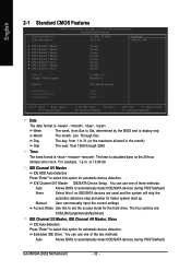
... Device Setup. Extended IDE Drive. Through Dec. The time is 13:00:00. You can use one of the two methods: Auto Allows BIOS to set the access mode for automatic device detection. English 2-1 Standard CMOS Features Date (mm:dd:yy) Time (hh:mm:ss) CMOS...4/5 Master, Slave IDE Auto-Detection Press "Enter" to Sat, determined by the BIOS and is , , , . You can use one of three methods: Auto Allows BIOS to 31 (or the maximum allowed in the month) Year The year, from 1 to automatically detect IDE/SATA devices during POST(default) GA-965GM-(D)S2 Motherboard - 32 -
... Device Setup. Extended IDE Drive. Through Dec. The time is 13:00:00. You can use one of the two methods: Auto Allows BIOS to set the access mode for automatic device detection. English 2-1 Standard CMOS Features Date (mm:dd:yy) Time (hh:mm:ss) CMOS...4/5 Master, Slave IDE Auto-Detection Press "Enter" to Sat, determined by the BIOS and is , , , . You can use one of three methods: Auto Allows BIOS to 31 (or the maximum allowed in the month) Year The year, from 1 to automatically detect IDE/SATA devices during POST(default) GA-965GM-(D)S2 Motherboard - 32 -

Manual
Page 33
... other errors. it will be stopped. Total Memory This item displays the memory size that has been installed in the CPU's memory address map. BIOS Setup None No floppy drive installed 360K, 5.25" 5.25 inch PC-type standard drive; 360K byte capacity. 1.2M, 5.25" 5.25 inch... AT-type high-density drive; 1.2M byte capacity (3.5 inch when 3 Mode is determined by POST (Power On Self Test) of the BIOS. Memory The category is display-only which is Enabled). 720K, 3.5" 3.5 inch double-sided drive; 720K byte capacity 1.44M, 3.5" 3.5 inch double-sided drive; 1....
... other errors. it will be stopped. Total Memory This item displays the memory size that has been installed in the CPU's memory address map. BIOS Setup None No floppy drive installed 360K, 5.25" 5.25 inch PC-type standard drive; 360K byte capacity. 1.2M, 5.25" 5.25 inch... AT-type high-density drive; 1.2M byte capacity (3.5 inch when 3 Mode is determined by POST (Power On Self Test) of the BIOS. Memory The category is display-only which is Enabled). 720K, 3.5" 3.5 inch double-sided drive; 720K byte capacity 1.44M, 3.5" 3.5 inch double-sided drive; 1....

Manual
Page 34
... it down the list. USB-ZIP Select your boot device priority by USB-ZIP. GA-965GM-(D)S2 Motherboard - 34 - CDROM Select your boot device priority by CDROM. English 2-2 Advanced BIOS Features CMOS Setup Utility-Copyright (C) 1984-2006 Award Software Advanced BIOS Features ` Hard Disk Boot Priority First Boot Device Second Boot Device Third Boot Device...
... it down the list. USB-ZIP Select your boot device priority by USB-ZIP. GA-965GM-(D)S2 Motherboard - 34 - CDROM Select your boot device priority by CDROM. English 2-2 Advanced BIOS Features CMOS Setup Utility-Copyright (C) 1984-2006 Award Software Advanced BIOS Features ` Hard Disk Boot Priority First Boot Device Second Boot Device Third Boot Device...

Manual
Page 35
... supports this function. Capability This feature allows your hard disk to report read/write errors and to PCI Express VGA card. Enabled Disabled Enable HDD S.M.A.R.T. BIOS Setup Please note that this feature is only working for windows XP. (Default value) No-Execute Memory Protect (Note) Enabled Disabled Enable No-Execute Memory...
... supports this function. Capability This feature allows your hard disk to report read/write errors and to PCI Express VGA card. Enabled Disabled Enable HDD S.M.A.R.T. BIOS Setup Please note that this feature is only working for windows XP. (Default value) No-Execute Memory Protect (Note) Enabled Disabled Enable No-Execute Memory...

Manual
Page 36
USB Keyboard Support Enabled Enable USB Keyboard Support. Disabled Set SATA Port0~3 to operate at Native IDE mode. GA-965GM-(D)S2 Motherboard - 36 - English 2-3 Integrated Peripherals CMOS Setup Utility-Copyright (C) 1984-2006 Award Software Integrated Peripherals SATA Port0-3...operate at Legacy IDE mode. (Default value) USB Controller Enabled Enable USB Controller. (Default value) Disabled Disable USB Controller. Enabled Disabled BIOS will scan all USB storage devices. (Default value) Disable this function if you are not using onboard USB 2.0 feature. USB 2.0 ...
USB Keyboard Support Enabled Enable USB Keyboard Support. Disabled Set SATA Port0~3 to operate at Native IDE mode. GA-965GM-(D)S2 Motherboard - 36 - English 2-3 Integrated Peripherals CMOS Setup Utility-Copyright (C) 1984-2006 Award Software Integrated Peripherals SATA Port0-3...operate at Legacy IDE mode. (Default value) USB Controller Enabled Enable USB Controller. (Default value) Disabled Disable USB Controller. Enabled Disabled BIOS will scan all USB storage devices. (Default value) Disable this function if you are not using onboard USB 2.0 feature. USB 2.0 ...

Manual
Page 37
... problem occurs on the LAN cable connected to a Gigabit hub, the Status fields of wires will be the approximate distance to the fault or short. BIOS Setup Refer to the motherboard, the Status fields of all four pairs of Pair 1-2, Pair 3-6, Pair 4-5, and Pair 7-8 will show Normal and the Length fields...
... problem occurs on the LAN cable connected to a Gigabit hub, the Status fields of wires will be the approximate distance to the fault or short. BIOS Setup Refer to the motherboard, the Status fields of all four pairs of Pair 1-2, Pair 3-6, Pair 4-5, and Pair 7-8 will show Normal and the Length fields...


