
Manual
Page 4
Table of Contents ItemChecklist ...6 OptionalAccessories ...6 GA-965G-DS3 Motherboard Layout 7 Block Diagram ...8 Chapter 1 Hardware Installation 9 1-1 Considerations Prior to Installation 9 1-2 Feature Summary 10 1-3 Installation of the CPU and CPU Cooler 12 1-3-1 Installation of the CPU 12 1-3-2 Installation of the CPU Cooler 13 1-4 Installation of Memory 14 1-5 Installation of Expansion Cards 16 1-6 I/O Back Panel Introduction 17 1-7 Connectors Introduction 18 Chapter...
Table of Contents ItemChecklist ...6 OptionalAccessories ...6 GA-965G-DS3 Motherboard Layout 7 Block Diagram ...8 Chapter 1 Hardware Installation 9 1-1 Considerations Prior to Installation 9 1-2 Feature Summary 10 1-3 Installation of the CPU and CPU Cooler 12 1-3-1 Installation of the CPU 12 1-3-2 Installation of the CPU Cooler 13 1-4 Installation of Memory 14 1-5 Installation of Expansion Cards 16 1-6 I/O Back Panel Introduction 17 1-7 Connectors Introduction 18 Chapter...

Manual
Page 8
...) VGA PCI Express x16 ATA-33/66/100/133 IDE Channel 2 SATA 3Gb/s GIGABYTE SATA2 LAN RJ45 Marvell 88E8056 PCI Express Bus x 1 x1 x1 x1 x1 PCIe CLK (100 MHz) 3 PCI Express x1 PCI Bus LGA775 Processor CPU CLK+/-(266/200/133 MHz) Host Interface DDRII 800/667/533 MHz DIMM(Note...
...) VGA PCI Express x16 ATA-33/66/100/133 IDE Channel 2 SATA 3Gb/s GIGABYTE SATA2 LAN RJ45 Marvell 88E8056 PCI Express Bus x 1 x1 x1 x1 x1 PCIe CLK (100 MHz) 3 PCI Express x1 PCI Bus LGA775 Processor CPU CLK+/-(266/200/133 MHz) Host Interface DDRII 800/667/533 MHz DIMM(Note...

Manual
Page 9
...the information in the provided manual. 3. Damage due to wear an electrostatic discharge (ESD) cuff when handling electronic components (CPU, RAM). 4. It is switched off the computer and unplug its components. 5. Turning on the computer power during the ... English Chapter 1 Hardware Installation 1-1 Considerations Prior to installing the electronic components, please have a problem related to be an unofficial Gigabyte product. - 9 - Prior to Installation Preparing Your Computer The motherboard contains numerous delicate electronic circuits and components which can lead to...
...the information in the provided manual. 3. Damage due to wear an electrostatic discharge (ESD) cuff when handling electronic components (CPU, RAM). 4. It is switched off the computer and unplug its components. 5. Turning on the computer power during the ... English Chapter 1 Hardware Installation 1-1 Considerations Prior to installing the electronic components, please have a problem related to be an unofficial Gigabyte product. - 9 - Prior to Installation Preparing Your Computer The motherboard contains numerous delicate electronic circuits and components which can lead to...

Manual
Page 10
...GIGABYTE SATA2 chip - 1 IDE connector (UDMA 33/ATA 66/ATA 100/ATA 133), allowing con- English 1-2 Feature Summary CPU Š LGA775 for additional 6 ports by cables Š 1 S/PDIF In connector Š 1 COMA connector Š 1 Chassis Intrusion connector Š 1 power LED connector GA-965G-DS3... connector Š 1 4-pin ATX 12V power connector Š 1 floppy connector Š 1 IDE connector Š 6 SATA 3Gb/s connectors Š 1 CPU fan connector Š 1 system fan connector Š 1 power fan connector Š 1 northbridge fan connector Š 1 front panel connector Š 1...
...GIGABYTE SATA2 chip - 1 IDE connector (UDMA 33/ATA 66/ATA 100/ATA 133), allowing con- English 1-2 Feature Summary CPU Š LGA775 for additional 6 ports by cables Š 1 S/PDIF In connector Š 1 COMA connector Š 1 Chassis Intrusion connector Š 1 power LED connector GA-965G-DS3... connector Š 1 4-pin ATX 12V power connector Š 1 floppy connector Š 1 IDE connector Š 6 SATA 3Gb/s connectors Š 1 CPU fan connector Š 1 system fan connector Š 1 power fan connector Š 1 northbridge fan connector Š 1 front panel connector Š 1...

Manual
Page 11
... Speaker Out/Side Speaker Out) I/O Control Š IT8718 chip Hardware Monitor Š System voltage detection Š CPU / System / Power temperature detection Š CPU / System / Power fan speed detection Š CPU warning temperature Š CPU / System fan failure warning Š CPU Smart Fan Control BIOS Š 1 8 Mbit flash ROM Š Use of licensed AWARD BIOS Š...
... Speaker Out/Side Speaker Out) I/O Control Š IT8718 chip Hardware Monitor Š System voltage detection Š CPU / System / Power temperature detection Š CPU / System / Power fan speed detection Š CPU warning temperature Š CPU / System fan failure warning Š CPU Smart Fan Control BIOS Š 1 8 Mbit flash ROM Š Use of licensed AWARD BIOS Š...

Manual
Page 12
... Technology and has it into its original position. Fig. 4 Once the CPU is installed on the CPU prior to system use, otherwise overheating and permanent damage of the CPU socket. Chipset: An Intel® Chipset that might cause damage to the CPU during installation.) GA-965G-DS3 Motherboard - 12 - HT functionality requirement content : Enabling the functionality of...
... Technology and has it into its original position. Fig. 4 Once the CPU is installed on the CPU prior to system use, otherwise overheating and permanent damage of the CPU socket. Chipset: An Intel® Chipset that might cause damage to the CPU during installation.) GA-965G-DS3 Motherboard - 12 - HT functionality requirement content : Enabling the functionality of...

Manual
Page 13
...the pin hole on the male push pin doesn't face inwards before installation. (This instruction is only for Intel boxed fan) Fig. 3 Place the CPU cooler atop the CPU and make sure the Male and Female push pin are joined closely. (for heat dissipation or using extreme care when removing the...heat paste on the motherboard. If the push pin is inserted as a result of hardening of the installed CPU. Fig. 6 Finally, please attach the power connector of the CPU cooler to the CPU as the picture, the installation is suggested that either thermal tape rather than heat paste be used for ...
...the pin hole on the male push pin doesn't face inwards before installation. (This instruction is only for Intel boxed fan) Fig. 3 Place the CPU cooler atop the CPU and make sure the Male and Female push pin are joined closely. (for heat dissipation or using extreme care when removing the...heat paste on the motherboard. If the push pin is inserted as a result of hardening of the installed CPU. Fig. 6 Finally, please attach the power connector of the CPU cooler to the CPU as the picture, the installation is suggested that either thermal tape rather than heat paste be used for ...

Manual
Page 19
... that is not connected, the system will not start . Before connecting the power connector, please make sure that can supply enough stable power to the CPU. Caution! It is unable to handle the system voltage requirements.
... that is not connected, the system will not start . Before connecting the power connector, please make sure that can supply enough stable power to the CPU. Caution! It is unable to handle the system voltage requirements.

Manual
Page 20
... connector wire is GND) NB_FAN : Pin No. Definition 1 1 GND 2 +12V 3 NC GA-965G-DS3 Motherboard - 20 - Most coolers are designed with color-coded power connector wires. Remember to connect the CPU/system/power fan cable to the CPU_FAN/SYS_FAN/PWR_FAN connector to prevent CPU damage or system hanging caused by overheating. 1 CPU_FAN 1 SYS_FAN 1 PWR_FAN CPU_FAN...
... connector wire is GND) NB_FAN : Pin No. Definition 1 1 GND 2 +12V 3 NC GA-965G-DS3 Motherboard - 20 - Most coolers are designed with color-coded power connector wires. Remember to connect the CPU/system/power fan cable to the CPU_FAN/SYS_FAN/PWR_FAN connector to prevent CPU damage or system hanging caused by overheating. 1 CPU_FAN 1 SYS_FAN 1 PWR_FAN CPU_FAN...

Manual
Page 31
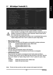
.... „ PC Health Status This setup page is the System auto detect Temperature, voltage, fan, speed. „ MB Intelligent Tweaker(M.I.T.) This setup page is control CPU clock and frequency ratio. „ Load Fail-Safe Defaults Fail-Safe Defaults indicates the value of the system parameters which the system would be in...
.... „ PC Health Status This setup page is the System auto detect Temperature, voltage, fan, speed. „ MB Intelligent Tweaker(M.I.T.) This setup page is control CPU clock and frequency ratio. „ Load Fail-Safe Defaults Fail-Safe Defaults indicates the value of the system parameters which the system would be in...

Manual
Page 33
... for systems with 512 K memory installed on the motherboard, or 640 K for all other errors. The value of base (or conventional) memory installed in the CPU's memory address map. Whenever the BIOS detects a non-fatal error the system will not stop for a disk error; Total Memory This item displays the memory...
... for systems with 512 K memory installed on the motherboard, or 640 K for all other errors. The value of base (or conventional) memory installed in the CPU's memory address map. Whenever the BIOS detects a non-fatal error the system will not stop for a disk error; Total Memory This item displays the memory...

Manual
Page 34
...The system will boot but will not access to 3 (Note) No-Execute Memory Protect (Note) Full Screen LOGO Show CPU Enhanced Halt (C1E)(Note) CPU Thermal Monitor 2(TM2) (Note) CPU EIST Function (Note) Virtualization Technology(Note) Init Display First Onboard VGA On-Chip Frame Buffer Size [Press Enter] [... F1: General Help F7: Optimized Defaults Hard Disk Boot Priority Select boot sequence for onboard(or add-on cards) SCSI, RAID, etc. GA-965G-DS3 Motherboard - 34 - USB-ZIP Select your boot device priority by USB-ZIP. USB-FDD Select your boot device priority by USB-FDD. Legacy...
...The system will boot but will not access to 3 (Note) No-Execute Memory Protect (Note) Full Screen LOGO Show CPU Enhanced Halt (C1E)(Note) CPU Thermal Monitor 2(TM2) (Note) CPU EIST Function (Note) Virtualization Technology(Note) Init Display First Onboard VGA On-Chip Frame Buffer Size [Press Enter] [... F1: General Help F7: Optimized Defaults Hard Disk Boot Priority Select boot sequence for onboard(or add-on cards) SCSI, RAID, etc. GA-965G-DS3 Motherboard - 34 - USB-ZIP Select your boot device priority by USB-ZIP. USB-FDD Select your boot device priority by USB-FDD. Legacy...

Manual
Page 35
...Memory Protect function. (Default value) Disabled Disable No-Execute Memory Protect function. CPU Enhanced Halt (C1E) (Note) Enabled Disabled Enable CPU Enhanced Halt (C1E) function. (Default value) Disable CPU Enhanced Halt (C1E) function. Init Display First This feature allows you to onboard... to "Disabled". Disable CPUID Limit for operating system with multi processors mode supported. (Default value) Disabled Disable CPU Hyper Threading. Virtualization Technology (Note) Enabled Disabled Enable Virtualization Technology. (Default value) Disable this item to 3 when use older OS...
...Memory Protect function. (Default value) Disabled Disable No-Execute Memory Protect function. CPU Enhanced Halt (C1E) (Note) Enabled Disabled Enable CPU Enhanced Halt (C1E) function. (Default value) Disable CPU Enhanced Halt (C1E) function. Init Display First This feature allows you to onboard... to "Disabled". Disable CPUID Limit for operating system with multi processors mode supported. (Default value) Disabled Disable CPU Hyper Threading. Virtualization Technology (Note) Enabled Disabled Enable Virtualization Technology. (Default value) Disable this item to 3 when use older OS...

Manual
Page 43
...fan fail warning function. (Default value) Enabled Enable the fan fail warning function. - 43 - BIOS Setup Current System/CPU Temperature Detect system/CPU temperature automatically. English 2-6 PC Health Status CMOS Setup Utility-Copyright (C) 1984-2006 Award Software PC Health Status Reset Case Open... Status Case Opened Vcore DDR18V +3.3V +12V Current System Temperature Current CPU Temperature Current CPU FAN Speed Current SYSTEM FAN Speed Current POWER FAN Speed CPU Warning Temperature CPU FAN Fail Warning SYSTEM FAN Fail Warning POWER FAN Fail Warning Smart FAN ...
...fan fail warning function. (Default value) Enabled Enable the fan fail warning function. - 43 - BIOS Setup Current System/CPU Temperature Detect system/CPU temperature automatically. English 2-6 PC Health Status CMOS Setup Utility-Copyright (C) 1984-2006 Award Software PC Health Status Reset Case Open... Status Case Opened Vcore DDR18V +3.3V +12V Current System Temperature Current CPU Temperature Current CPU FAN Speed Current SYSTEM FAN Speed Current POWER FAN Speed CPU Warning Temperature CPU FAN Fail Warning SYSTEM FAN Fail Warning POWER FAN Fail Warning Smart FAN ...

Manual
Page 44
... 0 is enabled. PWM Set to Intel(R) QST, make sure at different speed depending on CPU temperature. However, some 4-pin CPU fan power cables are not designed following Intel 4-Wire fans PWM control specifications. GA-965G-DS3 Motherboard - 44 - With such CPU fans, selecting PWM will be used for it. (Default Value) Voltage Set to Voltage when...
... 0 is enabled. PWM Set to Intel(R) QST, make sure at different speed depending on CPU temperature. However, some 4-pin CPU fan power cables are not designed following Intel 4-Wire fans PWM control specifications. GA-965G-DS3 Motherboard - 44 - With such CPU fans, selecting PWM will be used for it. (Default Value) Voltage Set to Voltage when...
Manual
Page 45
... a safe restart. When the "System Voltage Optimized" item blinks in red, it is overclocked and cannot restart, please wait 20secs. CPU Host Clock Control Please note that if your system is recommended that the M.I .A. 2 [Disabled] System Memory Multiplier (SPD) [Auto...Control [Manual] DDR2 OverVoltage Control [Normal] PCI-E OverVoltage Control [Normal] FSB OverVoltage Control [Normal] (G)MCH OverVoltage Control [Normal] CPU Voltage Control [Normal] Normal CPU Vcore 1.30000V Item Help Menu Level : Move Enter: Select F5: Previous Values +/-/PU/PD: Value F10: Save F6: Fail-...
... a safe restart. When the "System Voltage Optimized" item blinks in red, it is overclocked and cannot restart, please wait 20secs. CPU Host Clock Control Please note that if your system is recommended that the M.I .A. 2 [Disabled] System Memory Multiplier (SPD) [Auto...Control [Manual] DDR2 OverVoltage Control [Normal] PCI-E OverVoltage Control [Normal] FSB OverVoltage Control [Normal] (G)MCH OverVoltage Control [Normal] CPU Voltage Control [Normal] Normal CPU Vcore 1.30000V Item Help Menu Level : Move Enter: Select F5: Previous Values +/-/PU/PD: Value F10: Save F6: Fail-...
Manual
Page 46
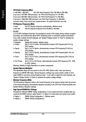
... Multiplier settings. If you overclock the DDR2 memory, select Option 1 or Option 2 to Cruise. (Automatically increase CPU frequency(5%,7%) by CPU loading. Turbo Set C.I .A.2 to help make your system broken. GA-965G-DS3 Motherboard - 46 - If you use a 800 MHz FSB processor, set "CPU Host Frequency" to 200 MHz. If you use a 1066 MHz FSB processor, set...
... Multiplier settings. If you overclock the DDR2 memory, select Option 1 or Option 2 to Cruise. (Automatically increase CPU frequency(5%,7%) by CPU loading. Turbo Set C.I .A.2 to help make your system broken. GA-965G-DS3 Motherboard - 46 - If you use a 800 MHz FSB processor, set "CPU Host Frequency" to 200 MHz. If you use a 1066 MHz FSB processor, set...
Manual
Page 47
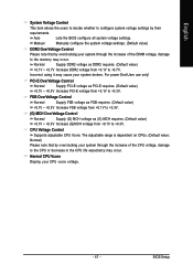
...DIMM voltage, damage to configure system voltage settings by overclocking your system through the increase of the CPU voltage, damage to +0.3V. CPU Voltage Control Supports adjustable CPU Vcore. BIOS Setup FSB OverVoltage Control Normal Supply FSB voltage as FSB requires. (Default value) ... voltage as (G) MCH requires. (Default value) +0.1V ~ +0.3V Increase (G)MCH voltage from +0.1V to the CPU or decrease in the CPU life expectancy may cause your CPU vcore voltage. - 47 - PCI-E OverVoltage Control Normal Supply PCI-E voltage as DDR2 requires. (Default value) +0.1V...
...DIMM voltage, damage to configure system voltage settings by overclocking your system through the increase of the CPU voltage, damage to +0.3V. CPU Voltage Control Supports adjustable CPU Vcore. BIOS Setup FSB OverVoltage Control Normal Supply FSB voltage as FSB requires. (Default value) ... voltage as (G) MCH requires. (Default value) +0.1V ~ +0.3V Increase (G)MCH voltage from +0.1V to the CPU or decrease in the CPU life expectancy may cause your CPU vcore voltage. - 47 - PCI-E OverVoltage Control Normal Supply PCI-E voltage as DDR2 requires. (Default value) +0.1V...
Manual
Page 55
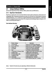
...setting page Enters the PC Health setting page Confirmation and Execution button Toggles between Easy and Advance Mode Display panel of both CPU cooling fan and North-Bridge Chipset cooling fan, 4) PC health for enhancing system performance, 2) C.I .B. 3. C.I ... 1. "Easy Mode" & "Advance Mode" 7. Appendix and M.I .B. and M.I .B. Overclocking 2. Function display LEDs 9. PC Health 5. Smart-Fan 4. GIGABYTE Logo 10. English Chapter 4 Appendix 4-1 Unique Software Utilities (Not all model support these Unique Software Utilities, please check your MB features.) 4-1-1 EasyTune 5 ...
...setting page Enters the PC Health setting page Confirmation and Execution button Toggles between Easy and Advance Mode Display panel of both CPU cooling fan and North-Bridge Chipset cooling fan, 4) PC health for enhancing system performance, 2) C.I .B. 3. C.I ... 1. "Easy Mode" & "Advance Mode" 7. Appendix and M.I .B. and M.I .B. Overclocking 2. Function display LEDs 9. PC Health 5. Smart-Fan 4. GIGABYTE Logo 10. English Chapter 4 Appendix 4-1 Unique Software Utilities (Not all model support these Unique Software Utilities, please check your MB features.) 4-1-1 EasyTune 5 ...

Manual
Page 64
...Advanced BIOS Features Hard Disk Boot Priority First Boot Device Second Boot Device Third Boot Device Password Check CPU Hyper-Threading Limit CPUID Max. English Step 2: To boot from Windows installation CD-ROM disk, set...Device under the Advanced BIOS Features menu to 3 No-Execute Memory Protect Full Screen LOGO Show CPU Enhanced Halt (C1E) CPU Thermal Monitor 2(TM2) CPU EIST Function Virtualization Technology Init Display First Onboard VGA On-Chip Frame Buffer Size [Press Enter]...-Safe Defaults Figure 2 ESC: Exit F1: General Help F7: Optimized Defaults GA-965G-DS3 Motherboard - 64 -
...Advanced BIOS Features Hard Disk Boot Priority First Boot Device Second Boot Device Third Boot Device Password Check CPU Hyper-Threading Limit CPUID Max. English Step 2: To boot from Windows installation CD-ROM disk, set...Device under the Advanced BIOS Features menu to 3 No-Execute Memory Protect Full Screen LOGO Show CPU Enhanced Halt (C1E) CPU Thermal Monitor 2(TM2) CPU EIST Function Virtualization Technology Init Display First Onboard VGA On-Chip Frame Buffer Size [Press Enter]...-Safe Defaults Figure 2 ESC: Exit F1: General Help F7: Optimized Defaults GA-965G-DS3 Motherboard - 64 -


