
Manual
Page 1
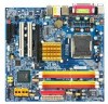
GA-945GM-S2 / GA-945GMF-S2 Intel® CoreTM 2 Extreme / CoreTM 2 Duo Intel® Pentium® D / Pentium® 4 LGA775 Processor Motherboard User's Manual Rev. 1002 12ME-945GMS2R-1002R * The WEEE marking on the product indicates this product must not be disposed of with user's other household waste and must be handed over to a designated collection point for the recycling of waste electrical and electronic equipment!! * The WEEE marking applies only in European Union's member states.
GA-945GM-S2 / GA-945GMF-S2 Intel® CoreTM 2 Extreme / CoreTM 2 Duo Intel® Pentium® D / Pentium® 4 LGA775 Processor Motherboard User's Manual Rev. 1002 12ME-945GMS2R-1002R * The WEEE marking on the product indicates this product must not be disposed of with user's other household waste and must be handed over to a designated collection point for the recycling of waste electrical and electronic equipment!! * The WEEE marking applies only in European Union's member states.

Manual
Page 2
Motherboard GA-945GM-S2 Jul. 7, 2006 Motherboard GA-945GM-S2 Jul. 7, 2006
Motherboard GA-945GM-S2 Jul. 7, 2006 Motherboard GA-945GM-S2 Jul. 7, 2006

Manual
Page 5
Table of Contents ItemChecklist ...7 OptionalAccessories ...7 GA-945GM-S2 / GA-945GMF-S2 Motherboard Layout 8 Block Diagram ...9 Chapter 1 Hardware Installation 11 1-1 Considerations Prior to Installation 11 1-2 Feature Summary 12 1-3 Installation ...16 1-5 Installation of Expansion Cards 18 1-6 I/O Back Panel Introduction 19 1-7 Connectors Introduction 20 Chapter 2 BIOS Setup 31 The Main Menu (For example: GA-945GMF-S2 BIOS Ver. : E1 32 2-1 Standard CMOS Features 34 2-2 Advanced BIOS Features 36 2-3 IntegratedPeripherals 38 2-4 Power Management Setup 41 2-5 PnP/PCI Configurations ...
Table of Contents ItemChecklist ...7 OptionalAccessories ...7 GA-945GM-S2 / GA-945GMF-S2 Motherboard Layout 8 Block Diagram ...9 Chapter 1 Hardware Installation 11 1-1 Considerations Prior to Installation 11 1-2 Feature Summary 12 1-3 Installation ...16 1-5 Installation of Expansion Cards 18 1-6 I/O Back Panel Introduction 19 1-7 Connectors Introduction 20 Chapter 2 BIOS Setup 31 The Main Menu (For example: GA-945GMF-S2 BIOS Ver. : E1 32 2-1 Standard CMOS Features 34 2-2 Advanced BIOS Features 36 2-3 IntegratedPeripherals 38 2-4 Power Management Setup 41 2-5 PnP/PCI Configurations ...

Manual
Page 8
GA-945GM-S2 / GA-945GMF-S2 Motherboard Layout IT8718 KB_MS ATX_12V LGA775 CPU_FAN VGA COMA LPT GA-945GM-S2 / GA-945GMF-S2 DDRII1 DDRII2 USB 1394* USB LAN F_AUDIO AUDIO BATTERY CLR_CMOS HDA_SUR SYS_FAN PCIE_16 RTL8111B PCI1 PCI2 CD_IN PCIE_1 CODEC SPDIF_IO FDD Intel® 945G BIOS Intel® ICH7 TSB43AB23* COMB F1_1394* F2_1394* DDRII3 DDRII4 SATAII0 SATAII2 IDE ATX F_PANEL SATAII1 SATAII3 CI F_USB1 F_USB2 PWR_LED "*" Only for GA-945GMF-S2. - 8 -
GA-945GM-S2 / GA-945GMF-S2 Motherboard Layout IT8718 KB_MS ATX_12V LGA775 CPU_FAN VGA COMA LPT GA-945GM-S2 / GA-945GMF-S2 DDRII1 DDRII2 USB 1394* USB LAN F_AUDIO AUDIO BATTERY CLR_CMOS HDA_SUR SYS_FAN PCIE_16 RTL8111B PCI1 PCI2 CD_IN PCIE_1 CODEC SPDIF_IO FDD Intel® 945G BIOS Intel® ICH7 TSB43AB23* COMB F1_1394* F2_1394* DDRII3 DDRII4 SATAII0 SATAII2 IDE ATX F_PANEL SATAII1 SATAII3 CI F_USB1 F_USB2 PWR_LED "*" Only for GA-945GMF-S2. - 8 -

Manual
Page 12
... additional 4 ports by cables Š 2 IEEE 1394a connectors for additional 2 ports by cables* Š 1 COMB connector Š 1 CI connector Š 1 power LED connector "*" Only for GA-945GMF-S2. GA-945GM-S2 / GA-945GMF-S2 Motherboard - 12 - TSB43AB23 chip Š 3 IEEE 1394a ports Storage Š Intel® ICH7 Southbrigde - 1 FDD connector, allowing connection of 1 FDD device - 1 IDE connector (IDE) with...
... additional 4 ports by cables Š 2 IEEE 1394a connectors for additional 2 ports by cables* Š 1 COMB connector Š 1 CI connector Š 1 power LED connector "*" Only for GA-945GMF-S2. GA-945GM-S2 / GA-945GMF-S2 Motherboard - 12 - TSB43AB23 chip Š 3 IEEE 1394a ports Storage Š Intel® ICH7 Southbrigde - 1 FDD connector, allowing connection of 1 FDD device - 1 IDE connector (IDE) with...

Manual
Page 14
... properly. Please make sure that supports HT Technology - Fig. 3 Notice the small gold colored triangle located on the CPU prior to the CPU during installation.) GA-945GM-S2 / GA-945GMF-S2 Motherboard - 14 - Align the indented corner of the CPU with the following platform components: - It is installed on the edge of the CPU socket. English...
... properly. Please make sure that supports HT Technology - Fig. 3 Notice the small gold colored triangle located on the CPU prior to the CPU during installation.) GA-945GM-S2 / GA-945GMF-S2 Motherboard - 14 - Align the indented corner of the CPU with the following platform components: - It is installed on the edge of the CPU socket. English...

Manual
Page 16
... the plastic clip at both edges of the DIMM sockets to remove the DIMM module. Insert the DIMM memory module vertically into the DIMM socket. GA-945GM-S2 / GA-945GMF-S2 Motherboard - 16 - A memory module can differ with the following conditions: 1. The motherboard supports DDRII memory modules, whereby BIOS will automatically detect memory capacity and specifications...
... the plastic clip at both edges of the DIMM sockets to remove the DIMM module. Insert the DIMM memory module vertically into the DIMM socket. GA-945GM-S2 / GA-945GMF-S2 Motherboard - 16 - A memory module can differ with the following conditions: 1. The motherboard supports DDRII memory modules, whereby BIOS will automatically detect memory capacity and specifications...

Manual
Page 17
..., SS: Single Side, "--": Empty) 2 memory modules 4 memory modules DDR II1 DS/SS - After operating the Dual Channel Technology, the bandwidth of Intel chipset specifications. 1. The GA-945GM-S2 / GA-945GMF-S2 includes 4 DIMM sockets, and each Channel has two DIMM sockets as following: Channel 0 : DDRII1, DDRII2 Channel 1 : DDRII3, DDRII4 If you must install them into DIMM... or four memory modules (it is installed. 2. DS/SS DS/SS DDR II3 DS/SS - DS/SS DDR II4 - English Dual Channel Memory Configuration The GA-945GM-S2 / GA-945GMF-S2 supports the Dual Channel Technology.
..., SS: Single Side, "--": Empty) 2 memory modules 4 memory modules DDR II1 DS/SS - After operating the Dual Channel Technology, the bandwidth of Intel chipset specifications. 1. The GA-945GM-S2 / GA-945GMF-S2 includes 4 DIMM sockets, and each Channel has two DIMM sockets as following: Channel 0 : DDRII1, DDRII2 Channel 1 : DDRII3, DDRII4 If you must install them into DIMM... or four memory modules (it is installed. 2. DS/SS DS/SS DDR II3 DS/SS - DS/SS DDR II4 - English Dual Channel Memory Configuration The GA-945GM-S2 / GA-945GMF-S2 supports the Dual Channel Technology.

Manual
Page 18
... 1-5 Installation of Expansion Cards You can also press the latch on the opposite side of the drawable bar as the picture to the left shows. GA-945GM-S2 / GA-945GMF-S2 Motherboard - 18 -
... 1-5 Installation of Expansion Cards You can also press the latch on the opposite side of the drawable bar as the picture to the left shows. GA-945GM-S2 / GA-945GMF-S2 Motherboard - 18 -

Manual
Page 20
English 1-7 Connectors Introduction 1 3 18 6 9 2 11 14 4 7 12 19 13 5 17 16* 15 8 10 1) ATX_12V 2) ATX (Power Connector) 3) CPU_FAN 4) SYS_FAN 5) FDD 6) IDE 7) SATAII0 / 1 / 2 / 3 8) PWR_LED 9) BATTERY 10) F_PANEL 11) F_AUDIO 12) CD_IN 13) SPDIF_IO 14) HDA_SUR 15) F_USB1 / F_USB2 16) F1_1394* / F2_1394* 17) COMB 18) CLR_CMOS 19) CI "*" Only for GA-945GMF-S2. GA-945GM-S2 / GA-945GMF-S2 Motherboard - 20 -
English 1-7 Connectors Introduction 1 3 18 6 9 2 11 14 4 7 12 19 13 5 17 16* 15 8 10 1) ATX_12V 2) ATX (Power Connector) 3) CPU_FAN 4) SYS_FAN 5) FDD 6) IDE 7) SATAII0 / 1 / 2 / 3 8) PWR_LED 9) BATTERY 10) F_PANEL 11) F_AUDIO 12) CD_IN 13) SPDIF_IO 14) HDA_SUR 15) F_USB1 / F_USB2 16) F1_1394* / F2_1394* 17) COMB 18) CLR_CMOS 19) CI "*" Only for GA-945GMF-S2. GA-945GM-S2 / GA-945GMF-S2 Motherboard - 20 -

Manual
Page 22
... +12V Sense 5) FDD (Floppy Connector) The FDD connector is the ground wire (GND). The types of the foolproof groove in the FDD connector. 33 1 34 2 GA-945GM-S2 / GA-945GMF-S2 Motherboard - 22 - Remember to connect the CPU/system fan cable to the CPU_FAN/SYS_FAN connector to the FDD drive. English 3/4) CPU_FAN / SYS_FAN (Cooler Fan Power...
... +12V Sense 5) FDD (Floppy Connector) The FDD connector is the ground wire (GND). The types of the foolproof groove in the FDD connector. 33 1 34 2 GA-945GM-S2 / GA-945GMF-S2 Motherboard - 22 - Remember to connect the CPU/system fan cable to the CPU_FAN/SYS_FAN connector to the FDD drive. English 3/4) CPU_FAN / SYS_FAN (Cooler Fan Power...

Manual
Page 24
... want to erase CMOS... 1. Re-install the battery. 4. Replace only with the system power indicator to indicate whether the system is incorrectly replaced. Turn off . GA-945GM-S2 / GA-945GMF-S2 Motherboard - 24 - Definition 1 MPD+ 2 MPD- 1 3 MPD- 9) BATTERY Danger of used batteries according to the manufacturer's instructions. Dispose of explosion if battery is on the computer...
... want to erase CMOS... 1. Re-install the battery. 4. Replace only with the system power indicator to indicate whether the system is incorrectly replaced. Turn off . GA-945GM-S2 / GA-945GMF-S2 Motherboard - 24 - Definition 1 MPD+ 2 MPD- 1 3 MPD- 9) BATTERY Danger of used batteries according to the manufacturer's instructions. Dispose of explosion if battery is on the computer...

Manual
Page 26
...: Pin No. 1 2 3 4 5 6 7 8 9 10 2 Definition MIC2_L GND MIC2_R -ACZ_DET LINE2_R FSENSE1 FAUDIO_JD No Pin LINE2_L FSENSE2 1 AC'97 Audio: Pin No. Definition 1 CD-L 1 2 GND 3 GND 4 CD-R GA-945GM-S2 / GA-945GMF-S2 Motherboard - 26 - English 11) F_AUDIO (Front Audio Connector) This connector supports either HD (High Definition) or AC97 front panel audio module.
...: Pin No. 1 2 3 4 5 6 7 8 9 10 2 Definition MIC2_L GND MIC2_R -ACZ_DET LINE2_R FSENSE1 FAUDIO_JD No Pin LINE2_L FSENSE2 1 AC'97 Audio: Pin No. Definition 1 CD-L 1 2 GND 3 GND 4 CD-R GA-945GM-S2 / GA-945GMF-S2 Motherboard - 26 - English 11) F_AUDIO (Front Audio Connector) This connector supports either HD (High Definition) or AC97 front panel audio module.

Manual
Page 28
... the front USB cable, incorrect connection between the cable and connector will make the device unable to work or even damage it . GA-945GM-S2 / GA-945GMF-S2 Motherboard - 28 - Check the pin assignment carefully while you connect the IEEE 1394 cable, incorrect connection between the cable and connector .... Definition 9 1 10 2 1 TPA+ 2 TPA- 3 GND 4 GND 5 TPB+ 6 TPB- 7 Power (12V) 8 Power (12V) 9 No Pin 10 GND "*" Only for GA-945GMF-S2. Pin No. English 15) F_ USB1 / F_USB2 (Front USB Connector) Be careful with the polarity of the IEEE 1394 connector.
... the front USB cable, incorrect connection between the cable and connector will make the device unable to work or even damage it . GA-945GM-S2 / GA-945GMF-S2 Motherboard - 28 - Check the pin assignment carefully while you connect the IEEE 1394 cable, incorrect connection between the cable and connector .... Definition 9 1 10 2 1 TPA+ 2 TPA- 3 GND 4 GND 5 TPB+ 6 TPB- 7 Power (12V) 8 Power (12V) 9 No Pin 10 GND "*" Only for GA-945GMF-S2. Pin No. English 15) F_ USB1 / F_USB2 (Front USB Connector) Be careful with the polarity of the IEEE 1394 connector.

Manual
Page 30
You can check the "Case Opened" status in BIOS Setup. English 19) CI (Chassis Intrusion, Case Open) This 2-pin connector allows your system to detect if the chassis cover is removed. Definition 1 Signal 1 2 GND GA-945GM-S2 / GA-945GMF-S2 Motherboard - 30 - Pin No.
You can check the "Case Opened" status in BIOS Setup. English 19) CI (Chassis Intrusion, Case Open) This 2-pin connector allows your system to detect if the chassis cover is removed. Definition 1 Signal 1 2 GND GA-945GM-S2 / GA-945GMF-S2 Motherboard - 30 - Pin No.

Manual
Page 32
... LS120 Hard Disk CDROM ZIP USB-FDD USB-ZIP USB-CDROM USB-HDD LAN KL:Move Enter :Accept ESC:Exit The Main Menu (For example: GA-945GMF-S2 BIOS Ver. : E1) Once you want, press "Ctrl+F1" to exit this chapter are for reference only and may differ from the exact ... accept . The BIOS Setup menus described in the BIOS Setup when somehow the system is not stable as figure below) will appear on cards) device. GA-945GM-S2 / GA-945GMF-S2 Motherboard - 32 - Press to access advanced options. 2. English : Boot Menu Select boot sequence for onboard (or add-on the screen. If you don't ...
... LS120 Hard Disk CDROM ZIP USB-FDD USB-ZIP USB-CDROM USB-HDD LAN KL:Move Enter :Accept ESC:Exit The Main Menu (For example: GA-945GMF-S2 BIOS Ver. : E1) Once you want, press "Ctrl+F1" to exit this chapter are for reference only and may differ from the exact ... accept . The BIOS Setup menus described in the BIOS Setup when somehow the system is not stable as figure below) will appear on cards) device. GA-945GM-S2 / GA-945GMF-S2 Motherboard - 32 - Press to access advanced options. 2. English : Boot Menu Select boot sequence for onboard (or add-on the screen. If you don't ...

Manual
Page 34
... and the system will skip the automatic detection step and allow for automatic device detection. Through Dec. The time is 13:00:00. time clock. GA-945GM-S2 / GA-945GMF-S2 Motherboard - 34 - IDE Channel 0 Master/Slave IDE HDD Auto-Detection Press "Enter" to select this if no IDE/SATA devices are used and the system...
... and the system will skip the automatic detection step and allow for automatic device detection. Through Dec. The time is 13:00:00. time clock. GA-945GM-S2 / GA-945GMF-S2 Motherboard - 34 - IDE Channel 0 Master/Slave IDE HDD Auto-Detection Press "Enter" to select this if no IDE/SATA devices are used and the system...

Manual
Page 36
... press to move it down the list. Select your boot device priority by Hard Disk. USB-CDROM Select your boot device priority by USB-CDROM. GA-945GM-S2 / GA-945GMF-S2 Motherboard - 36 - English 2-2 Advanced BIOS Features CMOS Setup Utility-Copyright (C) 1984-2006 Award Software Advanced BIOS Features ` Hard Disk Boot Priority First Boot Device Second...
... press to move it down the list. Select your boot device priority by Hard Disk. USB-CDROM Select your boot device priority by USB-CDROM. GA-945GM-S2 / GA-945GMF-S2 Motherboard - 36 - English 2-2 Advanced BIOS Features CMOS Setup Utility-Copyright (C) 1984-2006 Award Software Advanced BIOS Features ` Hard Disk Boot Priority First Boot Device Second...

Manual
Page 38
...Set On-Chip SATA mode to Enhanced, the motherboard allows up to 4 HDDs on the motherboard; 2 for SATA and the other for GA-945GMF-S2. Set On-Chip SATA mode to Non-Combined, SATA will auto set to Ch. 1 Master/Slave, this function will be ignored. Support... Defaults On-Chip Primary PCI IDE Enabled Enable onboard 1st channel IDE port. (Default value) Disabled Disable onboard 1st channel IDE port. GA-945GM-S2 / GA-945GMF-S2 Motherboard - 38 - English 2-3 Integrated Peripherals CMOS Setup Utility-Copyright (C) 1984-2006 Award Software Integrated Peripherals On-Chip Primary PCI IDE ...
...Set On-Chip SATA mode to Enhanced, the motherboard allows up to 4 HDDs on the motherboard; 2 for SATA and the other for GA-945GMF-S2. Set On-Chip SATA mode to Non-Combined, SATA will auto set to Ch. 1 Master/Slave, this function will be ignored. Support... Defaults On-Chip Primary PCI IDE Enabled Enable onboard 1st channel IDE port. (Default value) Disabled Disable onboard 1st channel IDE port. GA-945GM-S2 / GA-945GMF-S2 Motherboard - 38 - English 2-3 Integrated Peripherals CMOS Setup Utility-Copyright (C) 1984-2006 Award Software Integrated Peripherals On-Chip Primary PCI IDE ...

Manual
Page 40
... 3. (Default value) 1 Set ECP Mode Use DMA to 1. ECP+EPP Using Parallel port as Enhanced Parallel Port. ECP Using Parallel port as Extended Capabilities Port. GA-945GM-S2 / GA-945GMF-S2 Motherboard - 40 - English Onboard Serial Port 2 Auto BIOS will automatically setup the port 2 address. 3F8/IRQ4 Enable onboard Serial port 2 and address is 3F8/IRQ4...
... 3. (Default value) 1 Set ECP Mode Use DMA to 1. ECP+EPP Using Parallel port as Enhanced Parallel Port. ECP Using Parallel port as Extended Capabilities Port. GA-945GM-S2 / GA-945GMF-S2 Motherboard - 40 - English Onboard Serial Port 2 Auto BIOS will automatically setup the port 2 address. 3F8/IRQ4 Enable onboard Serial port 2 and address is 3F8/IRQ4...


