Manual
Page 5
Table of Contents ItemChecklist ...7 OptionalAccessories ...7 GA-945GM-S2/GA-945GM-DS2/GA-945GMF-DS2 Motherboard Layout 8 Block Diagram ...9 Chapter 1 Hardware Installation 11 1-1 Considerations Prior to Installation 11 1-2 Feature Summary 12... Installation of Expansion Cards 18 1-6 I/O Back Panel Introduction 19 1-7 Connectors Introduction 20 Chapter 2 BIOS Setup 31 The Main Menu (For example: GA-945GMF-DS2 BIOS Ver. : F1a 32 2-1 Standard CMOS Features 34 2-2 Advanced BIOS Features 36 2-3 IntegratedPeripherals 38 2-4 Power Management Setup 42 2-5 PnP/PCI Configurations 44 2-6 PC ...
Table of Contents ItemChecklist ...7 OptionalAccessories ...7 GA-945GM-S2/GA-945GM-DS2/GA-945GMF-DS2 Motherboard Layout 8 Block Diagram ...9 Chapter 1 Hardware Installation 11 1-1 Considerations Prior to Installation 11 1-2 Feature Summary 12... Installation of Expansion Cards 18 1-6 I/O Back Panel Introduction 19 1-7 Connectors Introduction 20 Chapter 2 BIOS Setup 31 The Main Menu (For example: GA-945GMF-DS2 BIOS Ver. : F1a 32 2-1 Standard CMOS Features 34 2-2 Advanced BIOS Features 36 2-3 IntegratedPeripherals 38 2-4 Power Management Setup 42 2-5 PnP/PCI Configurations 44 2-6 PC ...
Manual
Page 6
Chapter 3 Install Drivers 51 3-1 Install Chipset Drivers 51 3-2 SoftwareApplications 52 3-3 Driver CD Information 52 3-4 Hardware Information 53 3-5 Contact Us ...53 Chapter 4 Appendix 55 4-1 Unique Software Utilities 55 4-1-1 EasyTune 5 Introduction 55 4-1-2 Xpress Recovery2 Introduction 56 4-1-3 Flash BIOS Method Introduction 58 4-1-4 2- / 4- / 6- / 8- Channel Audio Function Introduction 67 4-2 Troubleshooting 72 - 6 -
Chapter 3 Install Drivers 51 3-1 Install Chipset Drivers 51 3-2 SoftwareApplications 52 3-3 Driver CD Information 52 3-4 Hardware Information 53 3-5 Contact Us ...53 Chapter 4 Appendix 55 4-1 Unique Software Utilities 55 4-1-1 EasyTune 5 Introduction 55 4-1-2 Xpress Recovery2 Introduction 56 4-1-3 Flash BIOS Method Introduction 58 4-1-4 2- / 4- / 6- / 8- Channel Audio Function Introduction 67 4-2 Troubleshooting 72 - 6 -
Manual
Page 8
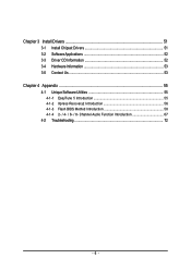
GA-945GM-S2/GA-945GM-DS2/GA-945GMF-DS2 Motherboard Layout KB_MS ATX_12V LGA775 CPU_FAN IT8718 VGA COMA LPT GA-945GM-S2/GA-945GM-DS2 /GA-945GMF-DS2 USB 1394 USB LAN F_AUDIO BATTERY CLR_CMOS AUDIO SYS_FAN PCIE_16 RTL8111B PCI1 PCI2 CD_IN PCIE_1 CODEC SPDIF_IO FDD Intel® 945G DDRII1 DDRII2 BIOS TSB43AB23 Intel® ICH7 COMB F1_1394 F2_1394 DDRII3 DDRII4 SATAII0 SATAII2 IDE ATX CI F_PANEL SATAII1 SATAII3 F_USB1 F_USB2 PWR_LED Only for GA-945GMF-DS2. - 8 -
GA-945GM-S2/GA-945GM-DS2/GA-945GMF-DS2 Motherboard Layout KB_MS ATX_12V LGA775 CPU_FAN IT8718 VGA COMA LPT GA-945GM-S2/GA-945GM-DS2 /GA-945GMF-DS2 USB 1394 USB LAN F_AUDIO BATTERY CLR_CMOS AUDIO SYS_FAN PCIE_16 RTL8111B PCI1 PCI2 CD_IN PCIE_1 CODEC SPDIF_IO FDD Intel® 945G DDRII1 DDRII2 BIOS TSB43AB23 Intel® ICH7 COMB F1_1394 F2_1394 DDRII3 DDRII4 SATAII0 SATAII2 IDE ATX CI F_PANEL SATAII1 SATAII3 F_USB1 F_USB2 PWR_LED Only for GA-945GMF-DS2. - 8 -
Manual
Page 9
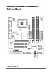
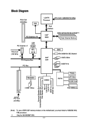
Only for GA-945GMF-DS2. - 9 - Block Diagram PCIe CLK (100 MHz) VGA PCI Express x16 PCI Express x1 PCIe CLK (100 MHz) x1 LAN RJ45 RTL 8111B x1 PCI Express ... Processor CPU CLK+/-(266/200/133 MHz) Host Interface Intel® 945G DDRII 667/533/400 MHz DIMM(Note) Dual Channel Memory Intel® ICH7 BIOS ATA-33/66/100 IDE Channel 4 SATA 3Gb/s 8 USB Ports TSB43AB23 2 PCI 3 IEEE 1394a PCI CLK (33 MHz) CODEC IT8718 Floppy LPT Port COM Ports...
Only for GA-945GMF-DS2. - 9 - Block Diagram PCIe CLK (100 MHz) VGA PCI Express x16 PCI Express x1 PCIe CLK (100 MHz) x1 LAN RJ45 RTL 8111B x1 PCI Express ... Processor CPU CLK+/-(266/200/133 MHz) Host Interface Intel® 945G DDRII 667/533/400 MHz DIMM(Note) Dual Channel Memory Intel® ICH7 BIOS ATA-33/66/100 IDE Channel 4 SATA 3Gb/s 8 USB Ports TSB43AB23 2 PCI 3 IEEE 1394a PCI CLK (33 MHz) CODEC IT8718 Floppy LPT Port COM Ports...
Manual
Page 13
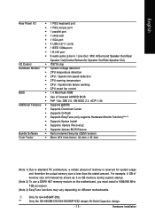
... Installation Only for system usage and therefore the actual memory size is less than the stated amount. "*" Only the GA-945GM-DS2/GA-945GMF-DS2 adopts All-Solid Capacitor design. - 13 - English Rear Panel I/O Š 1 PS/2 keyboard port Š 1 PS/2 mouse port Š 1 ... Š Supports EasyTune (only supports Hardware Monitor function)(Note 3) Š Supports Xpress Install Š Supports Xpress Recovery2 Š Supports Xpress BIOS Rescue Bundle Software Š Norton Internet Security (OEM revision) Form Factor Š Micro ATX form factor; 24.4cm x 23.3cm (Note...
... Installation Only for system usage and therefore the actual memory size is less than the stated amount. "*" Only the GA-945GM-DS2/GA-945GMF-DS2 adopts All-Solid Capacitor design. - 13 - English Rear Panel I/O Š 1 PS/2 keyboard port Š 1 PS/2 mouse port Š 1 ... Š Supports EasyTune (only supports Hardware Monitor function)(Note 3) Š Supports Xpress Install Š Supports Xpress Recovery2 Š Supports Xpress BIOS Rescue Bundle Software Š Norton Internet Security (OEM revision) Form Factor Š Micro ATX form factor; 24.4cm x 23.3cm (Note...
Manual
Page 14
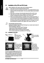
...on the CPU socket to system use, otherwise overheating and permanent damage of the CPU may occur. 5. If you wish to the CPU during installation.) GA-945GM(F)-(D)S2 Motherboard - 14 - If this occurs, please change the insert direction of the CPU. If you install the CPU in accordance with the ... the CPU and CPU cooler. 4. English 1-3 Installation of the CPU and CPU Cooler Before installing the CPU, please comply with the following platform components: - BIOS: A BIOS that might cause damage to set the CPU host frequency in the wrong direction, the CPU will not insert properly.
...on the CPU socket to system use, otherwise overheating and permanent damage of the CPU may occur. 5. If you wish to the CPU during installation.) GA-945GM(F)-(D)S2 Motherboard - 14 - If this occurs, please change the insert direction of the CPU. If you install the CPU in accordance with the ... the CPU and CPU cooler. 4. English 1-3 Installation of the CPU and CPU Cooler Before installing the CPU, please comply with the following platform components: - BIOS: A BIOS that might cause damage to set the CPU host frequency in the wrong direction, the CPU will not insert properly.
Manual
Page 16
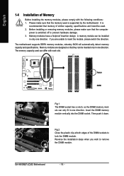
...has a notch, so the DIMM memory module can differ with the following conditions: 1. The motherboard supports DDRII memory modules, whereby BIOS will automatically detect memory capacity and specifications. The memory capacity used can only fit in only one direction. Insert the DIMM memory ...Reverse the installation steps when you are designed so that memory of similar capacity, specifications and brand be inserted only in one direction. GA-945GM(F)-(D)S2 Motherboard - 16 - Please make sure that the memory used . 2. Before installing or removing memory modules, please make ...
...has a notch, so the DIMM memory module can differ with the following conditions: 1. The motherboard supports DDRII memory modules, whereby BIOS will automatically detect memory capacity and specifications. The memory capacity used can only fit in only one direction. Insert the DIMM memory ...Reverse the installation steps when you are designed so that memory of similar capacity, specifications and brand be inserted only in one direction. GA-945GM(F)-(D)S2 Motherboard - 16 - Please make sure that the memory used . 2. Before installing or removing memory modules, please make ...
Manual
Page 18
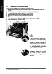
Power on the computer, if necessary, setup BIOS utility of expansion card from the computer. 3. Remove your VGA card is locked by following the steps outlined below: 1. GA-945GM(F)-(D)S2 Motherboard - 18 - Install related driver from the operating system. Replace the screw to secure the slot bracket ...before install the expansion card into expansion slot in the slot. 5. Make sure your computer's chassis cover, screws and slot bracket from BIOS. 8. Be sure the metal contacts on the slot. Please align the VGA card to the onboard PCI Express x16 slot and press firmly...
Power on the computer, if necessary, setup BIOS utility of expansion card from the computer. 3. Remove your VGA card is locked by following the steps outlined below: 1. GA-945GM(F)-(D)S2 Motherboard - 18 - Install related driver from the operating system. Replace the screw to secure the slot bracket ...before install the expansion card into expansion slot in the slot. 5. Make sure your computer's chassis cover, screws and slot bracket from BIOS. 8. Be sure the metal contacts on the slot. Please align the VGA card to the onboard PCI Express x16 slot and press firmly...
Manual
Page 23
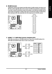
... the IDE cable, please take note of the foolproof groove in order to two IDE devices (hard drive or optical drive). Please refer to the BIOS setting for information on settings, please refer to the instructions located on one IDE cable, and the single IDE cable can provide up to the...
... the IDE cable, please take note of the foolproof groove in order to two IDE devices (hard drive or optical drive). Please refer to the BIOS setting for information on settings, please refer to the instructions located on one IDE cable, and the single IDE cable can provide up to the...
Manual
Page 29
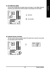
Open: Normal Short: Clear CMOS 18) CI (Chassis Intrusion, Case Open) This 2-pin connector allows your system to its default values by this header. Hardware Installation Pin No. English 17) CLR_CMOS (Clear CMOS) You may clear the CMOS data to detect if the chassis cover is removed. You can check the "Case Opened" status in BIOS Setup. To clear CMOS, temporarily short the two pins. Default doesn't include the jumper to avoid improper use of this header. Definition 1 Signal 1 2 GND - 29 -
Open: Normal Short: Clear CMOS 18) CI (Chassis Intrusion, Case Open) This 2-pin connector allows your system to its default values by this header. Hardware Installation Pin No. English 17) CLR_CMOS (Clear CMOS) You may clear the CMOS data to detect if the chassis cover is removed. You can check the "Case Opened" status in BIOS Setup. To clear CMOS, temporarily short the two pins. Default doesn't include the jumper to avoid improper use of this header. Definition 1 Signal 1 2 GND - 29 -
Manual
Page 31
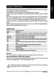
... in the CMOS SRAM of the screen. When the power is turned on the motherboard supplies the necessary power to a new BIOS, either GIGABYTE's Q-Flash or @BIOS utility can enter the BIOS setup screen by pressing "Ctrl + F1". When the power is turned off, the battery on , press the button during ...the BIOS POST (Power-On Self Test) will take you wish to upgrade to the CMOS SRAM. To exit the Help Window press . ...
... in the CMOS SRAM of the screen. When the power is turned on the motherboard supplies the necessary power to a new BIOS, either GIGABYTE's Q-Flash or @BIOS utility can enter the BIOS setup screen by pressing "Ctrl + F1". When the power is turned off, the battery on , press the button during ...the BIOS POST (Power-On Self Test) will take you wish to upgrade to the CMOS SRAM. To exit the Help Window press . ...
Manual
Page 32
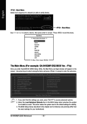
... stability. 3. This action makes the system reset to the default settings for 945GMF-DS2 F1a . . . . :BIOS Setup/Q-Flash, : Xpress Recovery2, : Boot Menu 10/13/2006-I945-6A79TG0ZC-00 : Boot Menu Use < > or < > to select a device, then press enter to access advanced ... LS120 Hard Disk CDROM ZIP USB-FDD USB-ZIP USB-CDROM USB-HDD LAN KL:Move Enter :Accept ESC:Exit The Main Menu (For example: GA-945GMF-DS2 BIOS Ver. : F1a) Once you want, press "Ctrl+F1" to accept . CMOS Setup Utility-Copyright (C) 1984-2006 Award Software ` Standard CMOS Features ` Advanced...
... stability. 3. This action makes the system reset to the default settings for 945GMF-DS2 F1a . . . . :BIOS Setup/Q-Flash, : Xpress Recovery2, : Boot Menu 10/13/2006-I945-6A79TG0ZC-00 : Boot Menu Use < > or < > to select a device, then press enter to access advanced ... LS120 Hard Disk CDROM ZIP USB-FDD USB-ZIP USB-CDROM USB-HDD LAN KL:Move Enter :Accept ESC:Exit The Main Menu (For example: GA-945GMF-DS2 BIOS Ver. : F1a) Once you want, press "Ctrl+F1" to accept . CMOS Setup Utility-Copyright (C) 1984-2006 Award Software ` Standard CMOS Features ` Advanced...
Manual
Page 33
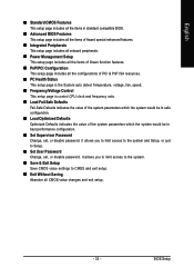
...system. „ Save & Exit Setup Save CMOS value settings to Setup. „ Set User Password Change, set , or disable password. BIOS Setup It allows you to limit access to the system and Setup, or just to CMOS and exit setup. „ Exit Without Saving Abandon...configuration. „ Load Optimized Defaults Optimized Defaults indicates the value of the system parameters which the system would be in standard compatible BIOS. „ Advanced BIOS Features This setup page includes all the items of Award special enhanced features. „ Integrated Peripherals This setup page includes all ...
...system. „ Save & Exit Setup Save CMOS value settings to Setup. „ Set User Password Change, set , or disable password. BIOS Setup It allows you to limit access to the system and Setup, or just to CMOS and exit setup. „ Exit Without Saving Abandon...configuration. „ Load Optimized Defaults Optimized Defaults indicates the value of the system parameters which the system would be in standard compatible BIOS. „ Advanced BIOS Features This setup page includes all the items of Award special enhanced features. „ Integrated Peripherals This setup page includes all ...
Manual
Page 34
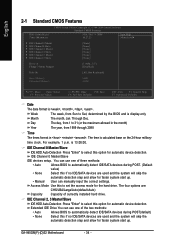
...For example, 1 p.m. IDE Channel 0 Master/Slave IDE devices setup. GA-945GM(F)-(D)S2 Motherboard - 34 - You can manually input the correct settings.... currectly installed hard drive. Extended IDE Drive You can use one of the two methods: • Auto Allows BIOS to set the access mode for faster system start up . Access Mode Use this to automatically detect IDE/SATA..., from 1999 through 2098 Time The times format in . Day The day, from Sun to Sat, determined by the BIOS and is , , , . English 2-1 Standard CMOS Features Date (mm:dd:yy) Time (hh:mm:ss) CMOS...
...For example, 1 p.m. IDE Channel 0 Master/Slave IDE devices setup. GA-945GM(F)-(D)S2 Motherboard - 34 - You can manually input the correct settings.... currectly installed hard drive. Extended IDE Drive You can use one of the two methods: • Auto Allows BIOS to set the access mode for faster system start up . Access Mode Use this to automatically detect IDE/SATA..., from 1999 through 2098 Time The times format in . Day The day, from Sun to Sat, determined by the BIOS and is , , , . English 2-1 Standard CMOS Features Date (mm:dd:yy) Time (hh:mm:ss) CMOS...
Manual
Page 35
...Use this information. The value of base (or conventional) memory installed in the CPU's memory address map. - 35 - BIOS Setup it will be prompted. Whenever the BIOS detects a non-fatal error the system will stop for any error that has been installed in the computer. All, But ...hard drive. it will not stop for a keyboard error; The two options are: Large/Auto(default:Auto) Capacity Capacity of the BIOS will not stop for all other errors. Hard drive information should be labeled on The category determines whether the computer will not stop for...
...Use this information. The value of base (or conventional) memory installed in the CPU's memory address map. - 35 - BIOS Setup it will be prompted. Whenever the BIOS detects a non-fatal error the system will stop for any error that has been installed in the computer. All, But ...hard drive. it will not stop for a keyboard error; The two options are: Large/Auto(default:Auto) Capacity Capacity of the BIOS will not stop for all other errors. Hard drive information should be labeled on The category determines whether the computer will not stop for...
Manual
Page 36
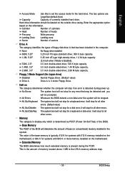
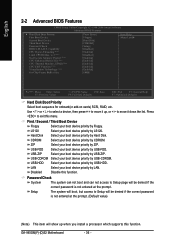
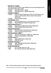
... add-on cards) SCSI, RAID, etc. Capability CPU Hyper-Threading (Note) Limit CPUID Max. CDROM Select your boot device priority by CDROM. GA-945GM(F)-(D)S2 Motherboard - 36 - to move it down the list. Use < > or < > to select a device, then press to ...move it up when you install a processor which supports this function. English 2-2 Advanced BIOS Features CMOS Setup Utility-Copyright (C) 1984-2006 Award Software Advanced BIOS Features ` Hard Disk Boot Priority First Boot Device Second Boot Device Third Boot Device Password Check HDD S.M.A.R.T. ...
... add-on cards) SCSI, RAID, etc. Capability CPU Hyper-Threading (Note) Limit CPUID Max. CDROM Select your boot device priority by CDROM. GA-945GM(F)-(D)S2 Motherboard - 36 - to move it down the list. Use < > or < > to select a device, then press to ...move it up when you install a processor which supports this function. English 2-2 Advanced BIOS Features CMOS Setup Utility-Copyright (C) 1984-2006 Award Software Advanced BIOS Features ` Hard Disk Boot Priority First Boot Device Second Boot Device Third Boot Device Password Check HDD S.M.A.R.T. ...
Manual
Page 37
... Memory Protect function. (Default value) Disabled Disable No-Execute Memory Protect function. capability. (Default value) CPU Hyper-Threading (Note) Enabled Enable CPU Hyper Threading Feature. BIOS Setup Capability This feature allows your hard disk to report read/write errors and to 3 when use older OS like NT4. Limit CPUID Max. On...
... Memory Protect function. (Default value) Disabled Disable No-Execute Memory Protect function. capability. (Default value) CPU Hyper-Threading (Note) Enabled Enable CPU Hyper Threading Feature. BIOS Setup Capability This feature allows your hard disk to report read/write errors and to 3 when use older OS like NT4. Limit CPUID Max. On...

Manual
Page 38
Auto Combined BIOS will auto detect. (Default value) Set On-Chip SATA mode to Combined, you can use...On-Chip SATA Mode Disabled Disable this function will auto set to 4 HDDs on the motherboard; 2 for SATA and the other for GA-945GMF-DS2. Support a maximum of 4 SATA devices. PATA IDE Set to Ch.0 Master/Slave Set PATA IDE to Ch. 0 Master/Slave. ..." and "PATA IDE Set to This value will be simulated to ". SATA Port 0/2 Set to This value will be ignored. GA-945GM(F)-(D)S2 Motherboard - 38 - Only for PATA. SATA Port 1/3 Set to ". PATA devices will auto make by the setting...
Auto Combined BIOS will auto detect. (Default value) Set On-Chip SATA mode to Combined, you can use...On-Chip SATA Mode Disabled Disable this function will auto set to 4 HDDs on the motherboard; 2 for SATA and the other for GA-945GMF-DS2. Support a maximum of 4 SATA devices. PATA IDE Set to Ch.0 Master/Slave Set PATA IDE to Ch. 0 Master/Slave. ..." and "PATA IDE Set to This value will be simulated to ". SATA Port 0/2 Set to This value will be ignored. GA-945GM(F)-(D)S2 Motherboard - 38 - Only for PATA. SATA Port 1/3 Set to ". PATA devices will auto make by the setting...
Manual
Page 39
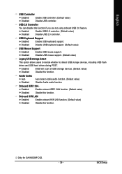
... drives during POST. Azalia Codec Auto Auto detect Azalia audio function. (Default value) Disabled Disable Azalia audio function. Only for GA-945GMF-DS2. - 39 - USB Keyboard Support Enabled Enable USB keyboard support. Disabled Disable USB keyboard support. (Default value) USB Mouse ...Support Enabled Disabled Enable USB mouse support. Enabled Disabled BIOS will scan all USB storage devices. (Default value) Disable this function. Onboard H/W 1394 Enabled Enable onboard IEEE 1394 function....
... drives during POST. Azalia Codec Auto Auto detect Azalia audio function. (Default value) Disabled Disable Azalia audio function. Only for GA-945GMF-DS2. - 39 - USB Keyboard Support Enabled Enable USB keyboard support. Disabled Disable USB keyboard support. (Default value) USB Mouse ...Support Enabled Disabled Enable USB mouse support. Enabled Disabled BIOS will scan all USB storage devices. (Default value) Disable this function. Onboard H/W 1394 Enabled Enable onboard IEEE 1394 function....
Manual
Page 41
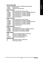
... chip. ECP+EPP Using LPT port as Enhanced Parallel Port. ECP Using LPT port as Extended Capabilities Port. Onboard Serial Port 2 Auto BIOS will automatically setup the port 1 address. 3F8/IRQ4 Enable onboard Serial port 1 and address is 3F8/IRQ4. (Default value) 2F8/IRQ3... 2E8/IRQ3 Enable onboard Serial port 1 and address is 2E8/IRQ3. Disabled Disable onboard Serial port 1. BIOS Setup Enabled Enable this function. (Default value) Onboard Serial Port 1 Auto BIOS will automatically setup the port 2 address. 3F8/IRQ4 Enable onboard Serial port 2 and address is 3F8/...
... chip. ECP+EPP Using LPT port as Enhanced Parallel Port. ECP Using LPT port as Extended Capabilities Port. Onboard Serial Port 2 Auto BIOS will automatically setup the port 1 address. 3F8/IRQ4 Enable onboard Serial port 1 and address is 3F8/IRQ4. (Default value) 2F8/IRQ3... 2E8/IRQ3 Enable onboard Serial port 1 and address is 2E8/IRQ3. Disabled Disable onboard Serial port 1. BIOS Setup Enabled Enable this function. (Default value) Onboard Serial Port 1 Auto BIOS will automatically setup the port 2 address. 3F8/IRQ4 Enable onboard Serial port 2 and address is 3F8/...


