Manual
Page 1
GA-945GM-S2 / GA-945GM-DS2 / GA-945GMF-DS2 Intel® CoreTM 2 Extreme dual-core / CoreTM 2 Duo Intel® Pentium® D / Pentium® 4 / Celeron® D LGA775 Processor Motherboard User's Manual Rev. 3901 12ME-945GMFDR-3901R * The WEEE marking on the product indicates this product must not be disposed of with user's other household waste and must be handed over to a designated collection point for the recycling of waste electrical and electronic equipment!! * The WEEE marking applies only in European Union's member states.
GA-945GM-S2 / GA-945GM-DS2 / GA-945GMF-DS2 Intel® CoreTM 2 Extreme dual-core / CoreTM 2 Duo Intel® Pentium® D / Pentium® 4 / Celeron® D LGA775 Processor Motherboard User's Manual Rev. 3901 12ME-945GMFDR-3901R * The WEEE marking on the product indicates this product must not be disposed of with user's other household waste and must be handed over to a designated collection point for the recycling of waste electrical and electronic equipment!! * The WEEE marking applies only in European Union's member states.
Manual
Page 3
Motherboard GA-945GM-S2 Jul. 7, 2006 Motherboard GA-945GM-S2 Jul. 7, 2006
Motherboard GA-945GM-S2 Jul. 7, 2006 Motherboard GA-945GM-S2 Jul. 7, 2006
Manual
Page 5
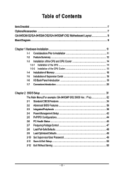
Table of Contents ItemChecklist ...7 OptionalAccessories ...7 GA-945GM-S2/GA-945GM-DS2/GA-945GMF-DS2 Motherboard Layout 8 Block Diagram ...9 Chapter 1 Hardware Installation 11 1-1 Considerations Prior to Installation 11 1-2 Feature Summary 12 1-3 ... 1-5 Installation of Expansion Cards 18 1-6 I/O Back Panel Introduction 19 1-7 Connectors Introduction 20 Chapter 2 BIOS Setup 31 The Main Menu (For example: GA-945GMF-DS2 BIOS Ver. : F1a 32 2-1 Standard CMOS Features 34 2-2 Advanced BIOS Features 36 2-3 IntegratedPeripherals 38 2-4 Power Management Setup 42 2-5 PnP/PCI Configurations...
Table of Contents ItemChecklist ...7 OptionalAccessories ...7 GA-945GM-S2/GA-945GM-DS2/GA-945GMF-DS2 Motherboard Layout 8 Block Diagram ...9 Chapter 1 Hardware Installation 11 1-1 Considerations Prior to Installation 11 1-2 Feature Summary 12 1-3 ... 1-5 Installation of Expansion Cards 18 1-6 I/O Back Panel Introduction 19 1-7 Connectors Introduction 20 Chapter 2 BIOS Setup 31 The Main Menu (For example: GA-945GMF-DS2 BIOS Ver. : F1a 32 2-1 Standard CMOS Features 34 2-2 Advanced BIOS Features 36 2-3 IntegratedPeripherals 38 2-4 Power Management Setup 42 2-5 PnP/PCI Configurations...
Manual
Page 8
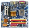
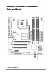
GA-945GM-S2/GA-945GM-DS2/GA-945GMF-DS2 Motherboard Layout KB_MS ATX_12V LGA775 CPU_FAN IT8718 VGA COMA LPT GA-945GM-S2/GA-945GM-DS2 /GA-945GMF-DS2 USB 1394 USB LAN F_AUDIO BATTERY CLR_CMOS AUDIO SYS_FAN PCIE_16 RTL8111B PCI1 PCI2 CD_IN PCIE_1 CODEC SPDIF_IO FDD Intel® 945G DDRII1 DDRII2 BIOS TSB43AB23 Intel® ICH7 COMB F1_1394 F2_1394 DDRII3 DDRII4 SATAII0 SATAII2 IDE ATX CI F_PANEL SATAII1 SATAII3 F_USB1 F_USB2 PWR_LED Only for GA-945GMF-DS2. - 8 -
GA-945GM-S2/GA-945GM-DS2/GA-945GMF-DS2 Motherboard Layout KB_MS ATX_12V LGA775 CPU_FAN IT8718 VGA COMA LPT GA-945GM-S2/GA-945GM-DS2 /GA-945GMF-DS2 USB 1394 USB LAN F_AUDIO BATTERY CLR_CMOS AUDIO SYS_FAN PCIE_16 RTL8111B PCI1 PCI2 CD_IN PCIE_1 CODEC SPDIF_IO FDD Intel® 945G DDRII1 DDRII2 BIOS TSB43AB23 Intel® ICH7 COMB F1_1394 F2_1394 DDRII3 DDRII4 SATAII0 SATAII2 IDE ATX CI F_PANEL SATAII1 SATAII3 F_USB1 F_USB2 PWR_LED Only for GA-945GMF-DS2. - 8 -
Manual
Page 12
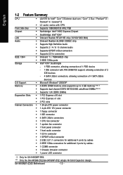
...; Supports High Definition Audio Š Supports 2 / 4 / 6 / 8 channel audio IEEE 1394 Š Supports S/PDIF In/Out connection Š Supports CD In connection Š Onboard T.I. "*" Only the GA-945GM-DS2/GA-945GMF-DS2 adopts All-Solid Capacitor design. GA-945GM(F)-(D)S2 Motherboard - 12 - English 1-2 Feature Summary CPU Š LGA775 for...
...; Supports High Definition Audio Š Supports 2 / 4 / 6 / 8 channel audio IEEE 1394 Š Supports S/PDIF In/Out connection Š Supports CD In connection Š Onboard T.I. "*" Only the GA-945GM-DS2/GA-945GMF-DS2 adopts All-Solid Capacitor design. GA-945GM(F)-(D)S2 Motherboard - 12 - English 1-2 Feature Summary CPU Š LGA775 for...
Manual
Page 14
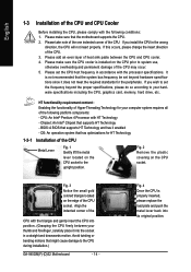
... change the insert direction of the CPU Metal Lever Fig. 1 Gently lift the metal lever located on the CPU prior to the CPU during installation.) GA-945GM(F)-(D)S2 Motherboard - 14 - It is not recommended that has optimizations for HT Technology 1-3-1 Installation of the CPU. 3. OS: An operation system that the system bus...
... change the insert direction of the CPU Metal Lever Fig. 1 Gently lift the metal lever located on the CPU prior to the CPU during installation.) GA-945GM(F)-(D)S2 Motherboard - 14 - It is not recommended that has optimizations for HT Technology 1-3-1 Installation of the CPU. 3. OS: An operation system that the system bus...
Manual
Page 16
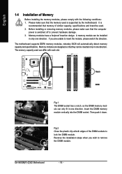
... can only fit in one direction. Notch DDRII Fig.1 The DIMM socket has a notch, so the DIMM memory module can differ with the following conditions: 1. GA-945GM(F)-(D)S2 Motherboard - 16 - A memory module can be inserted only in only one direction. Memory modules are unable to remove the DIMM module. Fig.2 Close the...
... can only fit in one direction. Notch DDRII Fig.1 The DIMM socket has a notch, so the DIMM memory module can differ with the following conditions: 1. GA-945GM(F)-(D)S2 Motherboard - 16 - A memory module can be inserted only in only one direction. Memory modules are unable to remove the DIMM module. Fig.2 Close the...
Manual
Page 17
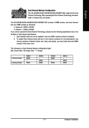
... modules DDR II1 DS/SS - DS/SS DDR II4 - DS/SS DS/SS - 17 - Dual Channel mode will double. English Dual Channel Memory Configuration The GA-945GM-S2/GA-945GM-DS2/GA-945GMF-DS2 supports the Dual Channel Technology. The GA-945GM-S2/GA-945GM-DS2/GA-945GMF-DS2 includes 4 DIMM sockets, and each Channel has two DIMM sockets as following is installed. 2.
... modules DDR II1 DS/SS - DS/SS DDR II4 - DS/SS DS/SS - 17 - Dual Channel mode will double. English Dual Channel Memory Configuration The GA-945GM-S2/GA-945GM-DS2/GA-945GMF-DS2 supports the Dual Channel Technology. The GA-945GM-S2/GA-945GM-DS2/GA-945GMF-DS2 includes 4 DIMM sockets, and each Channel has two DIMM sockets as following is installed. 2.
Manual
Page 18
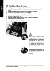
... card, users can install your expansion card by the small white-drawable bar. Replace your VGA card is locked by following the steps outlined below: 1. GA-945GM(F)-(D)S2 Motherboard - 18 - For example: Installing a PCI Express x16 VGA card: Please carefully pull out the small whitedrawable bar at the end of the PCI...
... card, users can install your expansion card by the small white-drawable bar. Replace your VGA card is locked by following the steps outlined below: 1. GA-945GM(F)-(D)S2 Motherboard - 18 - For example: Installing a PCI Express x16 VGA card: Please carefully pull out the small whitedrawable bar at the end of the PCI...
Manual
Page 20
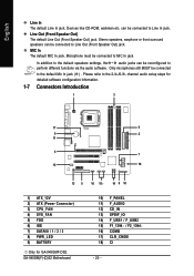
can be connected to Line In jack. Stereo speakers, earphone or front surround speakers can be reconfigured to the default Mic In jack ( ) . GA-945GM(F)-(D)S2 Motherboard 10) F_PANEL 11) F_AUDIO 12) CD_IN 13) SPDIF_IO 14) F_USB1 / F_USB2 15) F1_1394 / F2_1394 16) COMB 17) CLR_CMOS 18) CI - 20 - Line Out (Front ... information. 1-7 Connectors Introduction 1 3 17 6 9 2 11 4 7 12 18 13 5 16 15 14 8 10 1) ATX_12V 2) ATX (Power Connector) 3) CPU_FAN 4) SYS_FAN 5) FDD 6) IDE 7) SATAII0 / 1 / 2 / 3 8) PWR_LED 9) BATTERY Only for GA-945GMF-DS2.
can be connected to Line In jack. Stereo speakers, earphone or front surround speakers can be reconfigured to the default Mic In jack ( ) . GA-945GM(F)-(D)S2 Motherboard 10) F_PANEL 11) F_AUDIO 12) CD_IN 13) SPDIF_IO 14) F_USB1 / F_USB2 15) F1_1394 / F2_1394 16) COMB 17) CLR_CMOS 18) CI - 20 - Line Out (Front ... information. 1-7 Connectors Introduction 1 3 17 6 9 2 11 4 7 12 18 13 5 16 15 14 8 10 1) ATX_12V 2) ATX (Power Connector) 3) CPU_FAN 4) SYS_FAN 5) FDD 6) IDE 7) SATAII0 / 1 / 2 / 3 8) PWR_LED 9) BATTERY Only for GA-945GMF-DS2.
Manual
Page 22
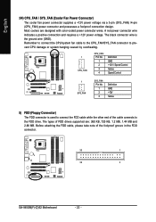
... CPU/system fan cable to the CPU_FAN/SYS_FAN connector to the FDD drive. The types of the foolproof groove in the FDD connector. 33 1 34 2 GA-945GM(F)-(D)S2 Motherboard - 22 -
... CPU/system fan cable to the CPU_FAN/SYS_FAN connector to the FDD drive. The types of the foolproof groove in the FDD connector. 33 1 34 2 GA-945GM(F)-(D)S2 Motherboard - 22 -
Manual
Page 24
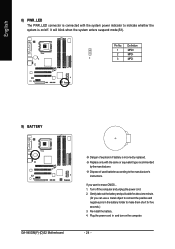
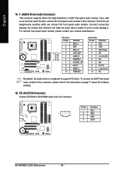
... on /off the computer and unplug the power cord. 2. It will blink when the system enters suspend mode(S1). Definition 1 MPD+ 2 MPD- 1 3 MPD- 9) BATTERY GA-945GM(F)-(D)S2 Motherboard Danger of used batteries according to erase CMOS... 1. Gently take out the battery and put it aside for about one minute. (Or you want...
... on /off the computer and unplug the power cord. 2. It will blink when the system enters suspend mode(S1). Definition 1 MPD+ 2 MPD- 1 3 MPD- 9) BATTERY GA-945GM(F)-(D)S2 Motherboard Danger of used batteries according to erase CMOS... 1. Gently take out the battery and put it aside for about one minute. (Or you want...
Manual
Page 26
... module, please contact your chassis manufacturer. To connect an AC97 front panel audio module to this connector. Pin No. Definition 1 CD-L 1 2 GND 3 GND 4 CD-R GA-945GM(F)-(D)S2 Motherboard - 26 - Incorrect connection between the module and connector will make the audio device unable to the connector. Definition Pin No. Definition 1 MIC2_L 1 MIC 2 GND...
... module, please contact your chassis manufacturer. To connect an AC97 front panel audio module to this connector. Pin No. Definition 1 CD-L 1 2 GND 3 GND 4 CD-R GA-945GM(F)-(D)S2 Motherboard - 26 - Incorrect connection between the module and connector will make the audio device unable to the connector. Definition Pin No. Definition 1 MIC2_L 1 MIC 2 GND...
Manual
Page 28
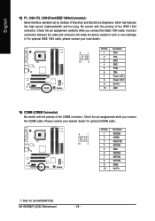
... will make the device unable to work or even damage it. GA-945GM(F)-(D)S2 Motherboard - 28 - For optional IEEE 1394 cable, please contact your nearest dealer for optional COMB cable. 9 1 10 2 Pin No. 1 2 3 4 5 6 7 8 9 10 Definition NDCDBNSINB NSOUTB NDTRBGND NDSRBNRTSBNCTSBNRIBNo Pin Only for GA-945GMF-DS2. Check the pin assignment carefully while you connect the COMB...
... will make the device unable to work or even damage it. GA-945GM(F)-(D)S2 Motherboard - 28 - For optional IEEE 1394 cable, please contact your nearest dealer for optional COMB cable. 9 1 10 2 Pin No. 1 2 3 4 5 6 7 8 9 10 Definition NDCDBNSINB NSOUTB NDTRBGND NDSRBNRTSBNCTSBNRIBNo Pin Only for GA-945GMF-DS2. Check the pin assignment carefully while you connect the COMB...

Manual
Page 30
English GA-945GM(F)-(D)S2 Motherboard - 30 -
English GA-945GM(F)-(D)S2 Motherboard - 30 -
Manual
Page 32
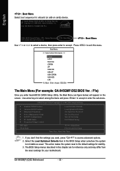
... LS120 Hard Disk CDROM ZIP USB-FDD USB-ZIP USB-CDROM USB-HDD LAN KL:Move Enter :Accept ESC:Exit The Main Menu (For example: GA-945GMF-DS2 BIOS Ver. : F1a) Once you want, press "Ctrl+F1" to access advanced options. 2. Use arrow keys to select among the items and press to.... Press to the default settings for stability. 3. If you don't find the settings you enter Award BIOS CMOS Setup Utility, the Main Menu (as usual. GA-945GM(F)-(D)S2 Motherboard - 32 - Award Modular BIOS v6.00PG, An Energy Star Ally Copyright (C) 1984-2006, Award Software, Inc. English : Boot Menu Select boot sequence...
... LS120 Hard Disk CDROM ZIP USB-FDD USB-ZIP USB-CDROM USB-HDD LAN KL:Move Enter :Accept ESC:Exit The Main Menu (For example: GA-945GMF-DS2 BIOS Ver. : F1a) Once you want, press "Ctrl+F1" to access advanced options. 2. Use arrow keys to select among the items and press to.... Press to the default settings for stability. 3. If you don't find the settings you enter Award BIOS CMOS Setup Utility, the Main Menu (as usual. GA-945GM(F)-(D)S2 Motherboard - 32 - Award Modular BIOS v6.00PG, An Energy Star Ally Copyright (C) 1984-2006, Award Software, Inc. English : Boot Menu Select boot sequence...
Manual
Page 34
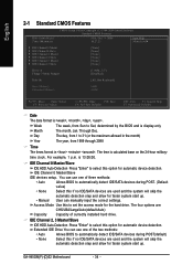
... faster system start up . • Manual User can use one of currectly installed hard drive. Extended IDE Drive You can manually input the correct settings. GA-945GM(F)-(D)S2 Motherboard - 34 - Week The week, from 1 to select this if no IDE/SATA devices are : CHS/LBA/Large/Auto(default:Auto) Capacity Capacity of...
... faster system start up . • Manual User can use one of currectly installed hard drive. Extended IDE Drive You can manually input the correct settings. GA-945GM(F)-(D)S2 Motherboard - 34 - Week The week, from 1 to select this if no IDE/SATA devices are : CHS/LBA/Large/Auto(default:Auto) Capacity Capacity of...
Manual
Page 36
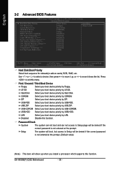
... Select your boot device priority by ZIP. USB-CDROM Select your boot device priority by USB-CDROM. Capability CPU Hyper-Threading (Note) Limit CPUID Max. GA-945GM(F)-(D)S2 Motherboard - 36 - USB-FDD USB-ZIP Select your boot device priority by USB-FDD. LAN Select your boot device priority by LAN.
... Select your boot device priority by ZIP. USB-CDROM Select your boot device priority by USB-CDROM. Capability CPU Hyper-Threading (Note) Limit CPUID Max. GA-945GM(F)-(D)S2 Motherboard - 36 - USB-FDD USB-ZIP Select your boot device priority by USB-FDD. LAN Select your boot device priority by LAN.

Manual
Page 38
...were set to This value will be ignored. Auto Combined BIOS will auto set to use; 4 for SATA and the other for GA-945GMF-DS2. On-Chip SATA Mode Disabled Disable this function will auto detect. (Default value) Set On-Chip SATA mode to Combined, you...HDDs to Ch. 0 Master/Slave. Support a maximum of 4 SATA devices. SATA Port 1/3 Set to This value will be simulated to ". GA-945GM(F)-(D)S2 Motherboard - 38 - English 2-3 Integrated Peripherals CMOS Setup Utility-Copyright (C) 1984-2006 Award Software Integrated Peripherals On-Chip Primary PCI IDE On-Chip SATA...
...were set to This value will be ignored. Auto Combined BIOS will auto set to use; 4 for SATA and the other for GA-945GMF-DS2. On-Chip SATA Mode Disabled Disable this function will auto detect. (Default value) Set On-Chip SATA mode to Combined, you...HDDs to Ch. 0 Master/Slave. Support a maximum of 4 SATA devices. SATA Port 1/3 Set to This value will be simulated to ". GA-945GM(F)-(D)S2 Motherboard - 38 - English 2-3 Integrated Peripherals CMOS Setup Utility-Copyright (C) 1984-2006 Award Software Integrated Peripherals On-Chip Primary PCI IDE On-Chip SATA...
Manual
Page 40
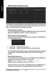
...-Safe Defaults ESC: Exit F1: General Help F7: Optimized Defaults This motherboard incorporates cable diagnostic feature designed to detect the status of the attachedLAN cable. GA-945GM(F)-(D)S2 Motherboard - 40 - This feature will show 0.0m, as shown in MS-DOS mode; Refer to the following message will appear: Start detecting at a normal...
...-Safe Defaults ESC: Exit F1: General Help F7: Optimized Defaults This motherboard incorporates cable diagnostic feature designed to detect the status of the attachedLAN cable. GA-945GM(F)-(D)S2 Motherboard - 40 - This feature will show 0.0m, as shown in MS-DOS mode; Refer to the following message will appear: Start detecting at a normal...


