Manual
Page 6
Only for GA-8N-SLI Royal. Table of Contents GA-8N-SLI Royal / GA-8N-SLI Pro / GA-8N-SLI Motherboard Layout 8 Block Diagram ...9 Chapter 1 Hardware Installation 11 1-1 Considerations Prior to Installation 11 1-2 Feature Summary 12 1-3 ... Link Interface) Configuration 20 1-9 I/O Back Panel Introduction 23 1-10 Connectors Introduction 24 Chapter 2 BIOS Setup 35 The Main Menu (For example: BIOS Ver. : GA-8N-SLI Royal F3l 36 2-1 Standard CMOS Features 38 2-2 Advanced BIOS Features 40 2-3 IntegratedPeripherals 42 2-4 Power Management Setup 45 2-5 PnP/PCI Configurations 47 2-6 PC ...
Only for GA-8N-SLI Royal. Table of Contents GA-8N-SLI Royal / GA-8N-SLI Pro / GA-8N-SLI Motherboard Layout 8 Block Diagram ...9 Chapter 1 Hardware Installation 11 1-1 Considerations Prior to Installation 11 1-2 Feature Summary 12 1-3 ... Link Interface) Configuration 20 1-9 I/O Back Panel Introduction 23 1-10 Connectors Introduction 24 Chapter 2 BIOS Setup 35 The Main Menu (For example: BIOS Ver. : GA-8N-SLI Royal F3l 36 2-1 Standard CMOS Features 38 2-2 Advanced BIOS Features 40 2-3 IntegratedPeripherals 42 2-4 Power Management Setup 45 2-5 PnP/PCI Configurations 47 2-6 PC ...
Manual
Page 7
Chapter 3 Drivers Installation 57 3-1 Install Chipset Drivers 57 3-2 SoftwareApplication 58 3-3 Software Information 58 3-4 Hardware Information 59 3-5 Contact Us ...59 Chapter 4 Appendix 61 4-1 Unique Software Utilities 61 4-1-1 EasyTune 5 Introduction 62 4-1-2 Xpress Recovery2 Introduction 63 4-1-3 Flash BIOS Method Introduction 65 4-1-4 Serial ATA BIOS Setting Utility Introduction 76 4-1-5 2- / 4- / 6- / 8- Channel Audio Function Introduction 87 4-2 Troubleshooting 91 - 7 -
Chapter 3 Drivers Installation 57 3-1 Install Chipset Drivers 57 3-2 SoftwareApplication 58 3-3 Software Information 58 3-4 Hardware Information 59 3-5 Contact Us ...59 Chapter 4 Appendix 61 4-1 Unique Software Utilities 61 4-1-1 EasyTune 5 Introduction 62 4-1-2 Xpress Recovery2 Introduction 63 4-1-3 Flash BIOS Method Introduction 65 4-1-4 Serial ATA BIOS Setting Utility Introduction 76 4-1-5 2- / 4- / 6- / 8- Channel Audio Function Introduction 87 4-2 Troubleshooting 91 - 7 -
Manual
Page 8
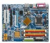
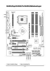
GA-8N-SLI Royal / GA-8N-SLI Pro / GA-8N-SLI Motherboard Layout KB_MS VRM_CONN COAXIAL ATX SPDIF_O LGA775 PWR_FAN COMA LPT GA-8N-SLI Royal (Pro)/GA-8N-SLI DDRII1 DDRII2 DDRII3 DDRII4 LAN1 LAN2 USB FDD USB Marvell Phy (LAN2) AUDIO1 AUDIO2 CPU_FAN ATX_12V nVIDIA® nForce 4 SLI Intel Edition F_AUDIO Marvell 8053 (LAN1) PCIE_12V Main BIOS Backup PCIE_2 BIOS NB_FAN PCIE_1 PCIE_16_1 SLI Switch Module Socket PCIE_16_2...
GA-8N-SLI Royal / GA-8N-SLI Pro / GA-8N-SLI Motherboard Layout KB_MS VRM_CONN COAXIAL ATX SPDIF_O LGA775 PWR_FAN COMA LPT GA-8N-SLI Royal (Pro)/GA-8N-SLI DDRII1 DDRII2 DDRII3 DDRII4 LAN1 LAN2 USB FDD USB Marvell Phy (LAN2) AUDIO1 AUDIO2 CPU_FAN ATX_12V nVIDIA® nForce 4 SLI Intel Edition F_AUDIO Marvell 8053 (LAN1) PCIE_12V Main BIOS Backup PCIE_2 BIOS NB_FAN PCIE_1 PCIE_16_1 SLI Switch Module Socket PCIE_16_2...
Manual
Page 9
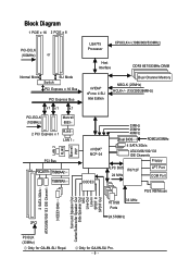
... x1 x1 x1 nVIDIA® nForce 4 SLI Intel Edition Dual Channel Memory NBCLK (25MHz) HCLK+/- (133/200/266MHz) PCI-ECLK (100MHz) Marvell 8053 2 PCI Express x 1 RJ45 LAN 1 PCI Bus PDC20779 TSB82AA2 TSB81BA3 LAN 2 RJ45 Marvell PHY nVIDIA® MCP-04 CODEC 33MHz 25MHz 48MHz Dual BIOS ROMCLK33MHz 4 SATA 3Gb/s ATA33/66/100... Channel 3 IEEE1394b Surround Speaker Out Center/Subwoofer Speaker Out Side Speaker Out MIC Line-Out Line-In SPDIF In SPDIF Out PCICLK (33MHz) Only for GA-8N-SLI Pro. - 9 - Only for GA-8N-SLI Royal.
... x1 x1 x1 nVIDIA® nForce 4 SLI Intel Edition Dual Channel Memory NBCLK (25MHz) HCLK+/- (133/200/266MHz) PCI-ECLK (100MHz) Marvell 8053 2 PCI Express x 1 RJ45 LAN 1 PCI Bus PDC20779 TSB82AA2 TSB81BA3 LAN 2 RJ45 Marvell PHY nVIDIA® MCP-04 CODEC 33MHz 25MHz 48MHz Dual BIOS ROMCLK33MHz 4 SATA 3Gb/s ATA33/66/100... Channel 3 IEEE1394b Surround Speaker Out Center/Subwoofer Speaker Out Side Speaker Out MIC Line-Out Line-In SPDIF In SPDIF Out PCICLK (33MHz) Only for GA-8N-SLI Pro. - 9 - Only for GA-8N-SLI Royal.
Manual
Page 13
...for GA-8N-SLI Pro. - 13 - Center/Subwoofer Speaker Out ; supports a maximum of licensed AWARD BIOS Supports Dual BIOS /Q-Flash/Multilanguage BIOS Supports U-Plus DPS Supports @BIOS Supports EasyTune 5 (Note 2) Over Voltage via BIOS (FSB/DIMM/PCIE/SATA II/CPU) Over Clock via BIOS (CPU...- supports data transfer rate of 2 SATA 3Gb/s connections - supports hot plugging function - supports a maximum of up to 300 MB/s - Only for GA-8N-SLI Royal. Surround Speaker Out (Rear Speaker Out) ; English Onboard Audio Š Š Š Š Š Š I/O Control Š...
...for GA-8N-SLI Pro. - 13 - Center/Subwoofer Speaker Out ; supports a maximum of licensed AWARD BIOS Supports Dual BIOS /Q-Flash/Multilanguage BIOS Supports U-Plus DPS Supports @BIOS Supports EasyTune 5 (Note 2) Over Voltage via BIOS (FSB/DIMM/PCIE/SATA II/CPU) Over Clock via BIOS (CPU...- supports data transfer rate of 2 SATA 3Gb/s connections - supports hot plugging function - supports a maximum of up to 300 MB/s - Only for GA-8N-SLI Royal. Surround Speaker Out (Rear Speaker Out) ; English Onboard Audio Š Š Š Š Š Š I/O Control Š...
Manual
Page 14
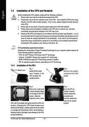
...please do so according to the upright position. CPU: An Intel® Pentium 4 Processor with the following platform components: - BIOS: A BIOS that might cause damage to set the frequency beyond hardware specifications since it does not meet the required standards for the peripherals. ... Fig. 3 Notice the small gold colored triangle located on the CPU socket. If you wish to the CPU during installation.) P4 nForce4 SLI Series Motherboard - 14 - Chipset: A NVIDIA® Chipset that has optimizations for your hardware specifications including the CPU, graphics card, memory...
...please do so according to the upright position. CPU: An Intel® Pentium 4 Processor with the following platform components: - BIOS: A BIOS that might cause damage to set the frequency beyond hardware specifications since it does not meet the required standards for the peripherals. ... Fig. 3 Notice the small gold colored triangle located on the CPU socket. If you wish to the CPU during installation.) P4 nForce4 SLI Series Motherboard - 14 - Chipset: A NVIDIA® Chipset that has optimizations for your hardware specifications including the CPU, graphics card, memory...
Manual
Page 16
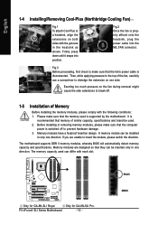
... Before installing the memory modules, please comply with the following conditions: 1. Memory modules have a foolproof insertion design. Only for GA-8N-SLI Royal. Firmly press down until it snaps into the NB_FAN connector. Before installing or removing memory modules, please make sure that... The motherboard supports DDR II memory modules, whereby BIOS will automatically detect memory capacity and specifications. The memory capacity used is properly affixed onto the heatsink, plug the power cable into position. Only for GA-8N-SLI Pro. Notch DDR II A memory module can ...
... Before installing the memory modules, please comply with the following conditions: 1. Memory modules have a foolproof insertion design. Only for GA-8N-SLI Royal. Firmly press down until it snaps into the NB_FAN connector. Before installing or removing memory modules, please make sure that... The motherboard supports DDR II memory modules, whereby BIOS will automatically detect memory capacity and specifications. The memory capacity used is properly affixed onto the heatsink, plug the power cable into position. Only for GA-8N-SLI Pro. Notch DDR II A memory module can ...

Manual
Page 18
...the screw to secure the slot bracket of the PCI Express x 16 slot when you try to install/ uninstall the VGA card. P4 nForce4 SLI Series Motherboard The PCIE_12V power connector supplies extra power to the onboard PCI Express x 16 slot and press firmly down on the computer, if necessary..., setup BIOS utility of Expansion Cards You can install your VGA card is locked by following the steps outlined below: 1. Read the related expansion card's ...
...the screw to secure the slot bracket of the PCI Express x 16 slot when you try to install/ uninstall the VGA card. P4 nForce4 SLI Series Motherboard The PCIE_12V power connector supplies extra power to the onboard PCI Express x 16 slot and press firmly down on the computer, if necessary..., setup BIOS utility of Expansion Cards You can install your VGA card is locked by following the steps outlined below: 1. Read the related expansion card's ...

Manual
Page 22
... bridge connector between the two cards, you plug the display cable to the card on the PCIE_16_2 slot, set Init Display First in BIOS Setup to PEG; if you must install the retention bracket included with the motherboard and secure the retention bracket to the chassis back panel...Card Driver Setting: Step 1: After installing graphics card driver in operating system, right-click the NVIDIA icon in the SLI multi-GPU dialog box. Then the SLI configuration is completed. P4 nForce4 SLI Series Motherboard - 22 - Make sure the two mini female slots on the top of both cards. System will...
... bridge connector between the two cards, you plug the display cable to the card on the PCIE_16_2 slot, set Init Display First in BIOS Setup to PEG; if you must install the retention bracket included with the motherboard and secure the retention bracket to the chassis back panel...Card Driver Setting: Step 1: After installing graphics card driver in operating system, right-click the NVIDIA icon in the SLI multi-GPU dialog box. Then the SLI configuration is completed. P4 nForce4 SLI Series Motherboard - 22 - Make sure the two mini female slots on the top of both cards. System will...
Manual
Page 28
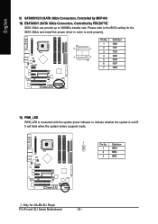
Please refer to work properly. Pin No. Only for the SATA 3Gb/s and install the proper driver in order to the BIOS setting for GA-8N-SLI Royal. English 9) SATAII0/1/2/3 (SATA 3Gb/s Connectors, Controlled by MCP-04) 10) ESATAII0/1 (SATA 3Gb/s Connectors, Controlled by PDC20779) SATA 3Gb/s...1 2 TXP 3 TXN 1 7 4 GND 5 RXN 6 RXP 7 GND 11) PWR_LED PWR_LED is connected with the system power indicator to 300MB/s transfer rate. P4 nForce4 SLI Series Motherboard - 28 - It will blink when the system enters suspend mode. 1 Pin No. Definition 1 MPD+ 2 MPD- 3 MPD-
Please refer to work properly. Pin No. Only for the SATA 3Gb/s and install the proper driver in order to the BIOS setting for GA-8N-SLI Royal. English 9) SATAII0/1/2/3 (SATA 3Gb/s Connectors, Controlled by MCP-04) 10) ESATAII0/1 (SATA 3Gb/s Connectors, Controlled by PDC20779) SATA 3Gb/s...1 2 TXP 3 TXN 1 7 4 GND 5 RXN 6 RXP 7 GND 11) PWR_LED PWR_LED is connected with the system power indicator to 300MB/s transfer rate. P4 nForce4 SLI Series Motherboard - 28 - It will blink when the system enters suspend mode. 1 Pin No. Definition 1 MPD+ 2 MPD- 3 MPD-
Manual
Page 33
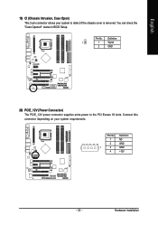
English 19) CI (Chassis Intrusion, Case Open) This 2-pin connector allows your system requirements. PIin No. Definition 1 NC 2 GND 1 3 GND 4 +12V - 33 - Pin No. Connect this connector depending on your system to the PCI Exress 16 slots. Definition 1 1 Signal 2 GND 20) PCIE_12V (Power Connector) The PCIE_12V power connector supplies extra power to detect if the chassis cover is removed. You can check the "Case Opened" status in BIOS Setup. Hardware Installation
English 19) CI (Chassis Intrusion, Case Open) This 2-pin connector allows your system requirements. PIin No. Definition 1 NC 2 GND 1 3 GND 4 +12V - 33 - Pin No. Connect this connector depending on your system to the PCI Exress 16 slots. Definition 1 1 Signal 2 GND 20) PCIE_12V (Power Connector) The PCIE_12V power connector supplies extra power to detect if the chassis cover is removed. You can check the "Case Opened" status in BIOS Setup. Hardware Installation
Manual
Page 35
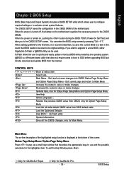
... a Windows-based utility that does not require users to boot to the CMOS SRAM. To exit the Help Window press . BIOS Setup Only for GA-8N-SLI Royal. When the power is recommended that you save changes into CMOS Status Page Setup Menu and Option Page Setup Menu - CONTROL KEYS...first time, it is turned off, the battery on , pushing the button during the BIOS POST (Power-On Self Test) will take you wish to upgrade to a new BIOS, either Gigabyte's Q-Flash or @BIOS utility can enter the BIOS setup screen by pressing "Ctrl + F1". Exit current page and return to use and...
... a Windows-based utility that does not require users to boot to the CMOS SRAM. To exit the Help Window press . BIOS Setup Only for GA-8N-SLI Royal. When the power is recommended that you save changes into CMOS Status Page Setup Menu and Option Page Setup Menu - CONTROL KEYS...first time, it is turned off, the battery on , pushing the button during the BIOS POST (Power-On Self Test) will take you wish to upgrade to a new BIOS, either Gigabyte's Q-Flash or @BIOS utility can enter the BIOS setup screen by pressing "Ctrl + F1". Exit current page and return to use and...
Manual
Page 36
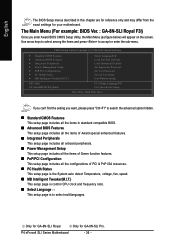
... Setup Utility, the Main Menu (as figure below) will appear on the screen. The Main Menu (For example: BIOS Ver. : GA-8N-SLI Royal F3l) Once you want, please press "Ctrl+F1" to search the advanced option hidden. „ Standard CMOS Features ... Motherboard - 36 - Use arrow keys to select among the items and press to select multilanguages. Only for GA-8N-SLI Pro. CMOS Setup Utility-Copyright (C) 1984-2005 Award Software ` Standard CMOS Features ` Advanced BIOS Features ` Integrated Peripherals ` Power Management Setup ` PnP/PCI Configurations ` PC Health Status ` MB Intelligent Tweaker(M.I...
... Setup Utility, the Main Menu (as figure below) will appear on the screen. The Main Menu (For example: BIOS Ver. : GA-8N-SLI Royal F3l) Once you want, please press "Ctrl+F1" to search the advanced option hidden. „ Standard CMOS Features ... Motherboard - 36 - Use arrow keys to select among the items and press to select multilanguages. Only for GA-8N-SLI Pro. CMOS Setup Utility-Copyright (C) 1984-2005 Award Software ` Standard CMOS Features ` Advanced BIOS Features ` Integrated Peripherals ` Power Management Setup ` PnP/PCI Configurations ` PC Health Status ` MB Intelligent Tweaker(M.I...
Manual
Page 37
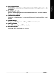
BIOS Setup It allows you to limit access to the system and Setup, or just to CMOS and exit setup. „ Exit Without Saving Abandon all ...
BIOS Setup It allows you to limit access to the system and Setup, or just to CMOS and exit setup. „ Exit Without Saving Abandon all ...
Manual
Page 38
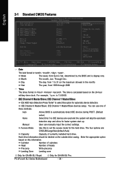
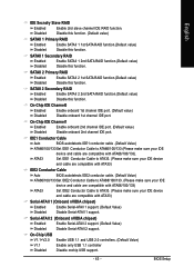
... automatically detect IDE devices during POST. (Default value) None Select this option for GA-8N-SLI Royal. IDE Channel 1 Master/Slave devices setup. Enter the appropriate option based on this to Sat, determined by the BIOS and is , , , . Cylinder Number of cylinders Head Number of currently installed...settings. Access Mode Use this information. Hard drive information should be labeled on the 24-hour military-time clock. Jan. Only for GA-8N-SLI Pro. English 2-1 Standard CMOS Features Date (mm:dd:yy) Time (hh:mm:ss) CMOS Setup Utility-Copyright (C) 1984-2005 ...
... automatically detect IDE devices during POST. (Default value) None Select this option for GA-8N-SLI Royal. IDE Channel 1 Master/Slave devices setup. Enter the appropriate option based on this to Sat, determined by the BIOS and is , , , . Cylinder Number of cylinders Head Number of currently installed...settings. Access Mode Use this information. Hard drive information should be labeled on the 24-hour military-time clock. Jan. Only for GA-8N-SLI Pro. English 2-1 Standard CMOS Features Date (mm:dd:yy) Time (hh:mm:ss) CMOS Setup Utility-Copyright (C) 1984-2005 ...
Manual
Page 39
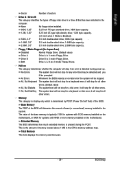
...Memory This item displays the memory size that has been installed in the computer. No Errors The system boot will determine the amount of the BIOS. it will stop for Japan Area) Disabled Normal Floppy Drive. (Default value) Drive A Drive A is detected during the POST. Both Drive... A & B are 3 mode Floppy Drives. it will stop for all other errors. All Errors Whenever the BIOS detects a non-fatal error the system will not stop for a keyboard or disk error; Memory The category is display-only which is typically 512K...
...Memory This item displays the memory size that has been installed in the computer. No Errors The system boot will determine the amount of the BIOS. it will stop for Japan Area) Disabled Normal Floppy Drive. (Default value) Drive A Drive A is detected during the POST. Both Drive... A & B are 3 mode Floppy Drives. it will stop for all other errors. All Errors Whenever the BIOS detects a non-fatal error the system will not stop for a keyboard or disk error; Memory The category is display-only which is typically 512K...
Manual
Page 40
... Set boot ROM order to devices on the Promise controller. (Default) Nvidia RAID Set boot ROM order to move it down the list. P4 nForce4 SLI Series Motherboard - 40 - Use < > or < > to select a device, then press to devices on cards) SCSI, RAID, etc. USB-ZIP Select ...device priority by Hard Disk. CDROM Select your boot device priority by CDROM. Only for GA-8N-SLI Royal. Boot Up Floppy Seek During POST, BIOS will show up , or to exit this function. Only for GA-8N-SLI Pro. LS120 Select your boot device priority by LS120. to SCSI devices. USB-CDROM ...
... Set boot ROM order to devices on the Promise controller. (Default) Nvidia RAID Set boot ROM order to move it down the list. P4 nForce4 SLI Series Motherboard - 40 - Use < > or < > to select a device, then press to devices on cards) SCSI, RAID, etc. USB-ZIP Select ...device priority by Hard Disk. CDROM Select your boot device priority by CDROM. Only for GA-8N-SLI Royal. Boot Up Floppy Seek During POST, BIOS will show up , or to exit this function. Only for GA-8N-SLI Pro. LS120 Select your boot device priority by LS120. to SCSI devices. USB-CDROM ...
Manual
Page 41
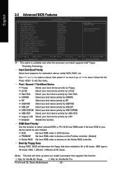
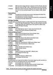
...value to PCI VGA card. Full Screen LOGO Show Enabled Disabled Display Full Screen Logo during POST. (Defaults value) Do not display Full Screen Logo. BIOS Setup Enabled Enable CPU Hyper-Threading feature. PEG Set Init Display First to PCI Express VGA card (Slot1). (Default value) PEG (Slot2) Set ... value) Disabled Disable CPU Enhanced Halt (C1E) function. PCI Slot Set Init Display First to 3 when using older OS like NT4. Note that BIOS can not access to Setup will not search for the type of the monitor display from 720K, 1.2M or 1.44M drive type as they are...
...value to PCI VGA card. Full Screen LOGO Show Enabled Disabled Display Full Screen Logo during POST. (Defaults value) Do not display Full Screen Logo. BIOS Setup Enabled Enable CPU Hyper-Threading feature. PEG Set Init Display First to PCI Express VGA card (Slot1). (Default value) PEG (Slot2) Set ... value) Disabled Disable CPU Enhanced Halt (C1E) function. PCI Slot Set Init Display First to 3 when using older OS like NT4. Note that BIOS can not access to Setup will not search for the type of the monitor display from 720K, 1.2M or 1.44M drive type as they are...
Manual
Page 43
...On-Chip IDE Channel1 Enabled Enable onboard 2nd channel IDE port. (Default value) Disabled Disable onboard 2nd channel IDE port. BIOS Setup IDE1 Conductor Cable Auto BIOS autodetects IDE1 conductor cable .(Default Value) ATA66/100/133 Set IDE1 Conductor Cable to ATA33. (Please make sure your IDE ... ATA33 Set IDE1 Conductor Cable to ATA33. (Please make sure your IDE device and cable are compatible with ATA33) IDE2 Conductor Cable Auto BIOS autodetects IDE2 conductor cable. (Default Value) ATA66/100/133 Set IDE2 Conductor Cable to ATA66/100/133. (Please make sure your IDE ...
...On-Chip IDE Channel1 Enabled Enable onboard 2nd channel IDE port. (Default value) Disabled Disable onboard 2nd channel IDE port. BIOS Setup IDE1 Conductor Cable Auto BIOS autodetects IDE1 conductor cable .(Default Value) ATA66/100/133 Set IDE1 Conductor Cable to ATA33. (Please make sure your IDE ... ATA33 Set IDE1 Conductor Cable to ATA33. (Please make sure your IDE device and cable are compatible with ATA33) IDE2 Conductor Cable Auto BIOS autodetects IDE2 conductor cable. (Default Value) ATA66/100/133 Set IDE2 Conductor Cable to ATA66/100/133. (Please make sure your IDE ...
Manual
Page 44
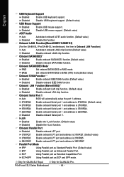
... onboard AC'97 audio function. (Default value) Disabled Disable this function. Onboard LAN2 Function (Marvell 88E1111/88E1115) (For the GA-8N-SLI Pro/GA-8N-SLI motherboard, the item is 3BC/IRQ7. Onboard LAN Function (Marvell 8053) Enabled Enable onboard LAN chip function. (Default value) ...Default value) Onboard 1394b Function Enabled Enable onboard IEEE1394b function.(Default value) Disabled Disable onboard IEEE1394b function. Onboard Serial Port 1 Auto BIOS will automatically setup the port 1 address. 3F8/IRQ4 Enable onboard Serial port 1 and address is 3F8/IRQ4. (Default value)...
... onboard AC'97 audio function. (Default value) Disabled Disable this function. Onboard LAN2 Function (Marvell 88E1111/88E1115) (For the GA-8N-SLI Pro/GA-8N-SLI motherboard, the item is 3BC/IRQ7. Onboard LAN Function (Marvell 8053) Enabled Enable onboard LAN chip function. (Default value) ...Default value) Onboard 1394b Function Enabled Enable onboard IEEE1394b function.(Default value) Disabled Disable onboard IEEE1394b function. Onboard Serial Port 1 Auto BIOS will automatically setup the port 1 address. 3F8/IRQ4 Enable onboard Serial port 1 and address is 3F8/IRQ4. (Default value)...


