Manual
Page 4
...GA-8I945GMF Motherboard Layout 6 Block Diagram ...7 Chapter 1 Hardware Installation 9 1-1 Considerations Prior to Installation 9 1-2 Feature Summary 10 1-3 Installation of the CPU and Heatsink 12 1-3-1 Installation of the CPU 12 1-3-2 Installation of the Heatsink 13 1-4 Installation of Memory 14 1-5 Install expansion cards 16 1-6 I/O Back Panel Introduction 17 1-7 Connectors Introduction 18 Chapter 2 BIOS... Setup 29 The Main Menu (For example: BIOS Ver. : F2 30 2-1 Standard CMOS Features 32 2-2 Advanced BIOS Features 35 2-3 IntegratedPeripherals ...
...GA-8I945GMF Motherboard Layout 6 Block Diagram ...7 Chapter 1 Hardware Installation 9 1-1 Considerations Prior to Installation 9 1-2 Feature Summary 10 1-3 Installation of the CPU and Heatsink 12 1-3-1 Installation of the CPU 12 1-3-2 Installation of the Heatsink 13 1-4 Installation of Memory 14 1-5 Install expansion cards 16 1-6 I/O Back Panel Introduction 17 1-7 Connectors Introduction 18 Chapter 2 BIOS... Setup 29 The Main Menu (For example: BIOS Ver. : F2 30 2-1 Standard CMOS Features 32 2-2 Advanced BIOS Features 35 2-3 IntegratedPeripherals ...
Manual
Page 5
Chapter 3 Install Drivers 51 3-1 Install Chipset Drivers 51 3-2 SoftwareApplications 52 3-3 Driver CD Information 52 3-4 Hardware Information 53 3-5 Contact Us ...53 Chapter 4 Appendix 55 4-1 Unique Software Utilities 55 4-1-1 EasyTune 5 Introduction 56 4-1-2 Xpress Recovery2 Introduction 57 4-1-3 Flash BIOS Method Introduction 60 4-1-4 2- / 4- / 6- / 8- Channel Audio Function Introduction 69 4-2 Troubleshooting 73 - 5 -
Chapter 3 Install Drivers 51 3-1 Install Chipset Drivers 51 3-2 SoftwareApplications 52 3-3 Driver CD Information 52 3-4 Hardware Information 53 3-5 Contact Us ...53 Chapter 4 Appendix 55 4-1 Unique Software Utilities 55 4-1-1 EasyTune 5 Introduction 56 4-1-2 Xpress Recovery2 Introduction 57 4-1-3 Flash BIOS Method Introduction 60 4-1-4 2- / 4- / 6- / 8- Channel Audio Function Introduction 69 4-2 Troubleshooting 73 - 5 -
Manual
Page 6
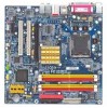
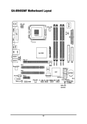
GA-8I945GMF Motherboard Layout COMA LPT KB_MS ATX_12V LGA775 CPU_FAN IT8712F RF_ID ATX VGA GA-8I945GMF USB USB 1394 LAN Intel 945G F_AUDIO AUDIO1 AUDIO2 PCIE_16 PCI1 Marvell 8053 PCI2 CD_IN PCIE_1 CODEC SPDIF_IO COMB DDRII1 DDRII2 DDRII3 DDRII4 IDE FDD BIOS SATAII2_3 ICH7 BATTERY TSB43AB23 SATAII0_1 CI SYS_FAN F1_1394 F2_1394 GREEN_USB F_USB CLR_CMOS F_PANEL PWR_LED (Optional) - 6 -
GA-8I945GMF Motherboard Layout COMA LPT KB_MS ATX_12V LGA775 CPU_FAN IT8712F RF_ID ATX VGA GA-8I945GMF USB USB 1394 LAN Intel 945G F_AUDIO AUDIO1 AUDIO2 PCIE_16 PCI1 Marvell 8053 PCI2 CD_IN PCIE_1 CODEC SPDIF_IO COMB DDRII1 DDRII2 DDRII3 DDRII4 IDE FDD BIOS SATAII2_3 ICH7 BATTERY TSB43AB23 SATAII0_1 CI SYS_FAN F1_1394 F2_1394 GREEN_USB F_USB CLR_CMOS F_PANEL PWR_LED (Optional) - 6 -
Manual
Page 7
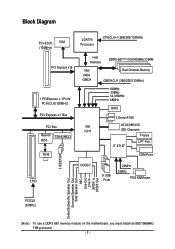
.../200/133MHz) Host Interface DDRII 667(Note)/533/400MHz DIMM Intel 945G GMCH Dual Channel Memory GMCHCLK (266/200/133MHz) 66MHz 33MHz 14.318MHz 48MHz BIOS 4 Serial ATAII Intel ATA33/66/100 ICH7 IDE Channels Floppy IT 8712F LPT Port COM Ports 3 IEEE1394 2 PCI CODEC 8 USB Ports 24MHz 33MHz PS/2 KB...
.../200/133MHz) Host Interface DDRII 667(Note)/533/400MHz DIMM Intel 945G GMCH Dual Channel Memory GMCHCLK (266/200/133MHz) 66MHz 33MHz 14.318MHz 48MHz BIOS 4 Serial ATAII Intel ATA33/66/100 ICH7 IDE Channels Floppy IT 8712F LPT Port COM Ports 3 IEEE1394 2 PCI CODEC 8 USB Ports 24MHz 33MHz PS/2 KB...
Manual
Page 11
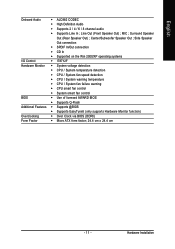
... fan failure warning Š CPU smart fan control Š System smart fan control BIOS Š Use of licensed AWARD BIOS Š Supports Q-Flash Additional Features Š Supports @BIOS Š Supports EasyTune5 (only supports Hardware Monitor function) Overclocking Š Over Clock via BIOS (DDRII) Form Factor Š Micro ATX form factor; 24.4 cm x 24.4 cm...
... fan failure warning Š CPU smart fan control Š System smart fan control BIOS Š Use of licensed AWARD BIOS Š Supports Q-Flash Additional Features Š Supports @BIOS Š Supports EasyTune5 (only supports Hardware Monitor function) Overclocking Š Over Clock via BIOS (DDRII) Form Factor Š Micro ATX form factor; 24.4 cm x 24.4 cm...
Manual
Page 12
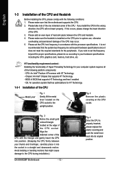
...Metal Lever Fig. 1 Gently lift the metal lever located on the CPU prior to your computer system requires all of the following conditions: 1. BIOS: A BIOS that the motherboard supports the CPU. 2. Fig. 4 Once the CPU is properly inserted, please replace the plastic covering and push the metal lever...4. Align the indented corner of the CPU with HT Technology - It is installed on the CPU socket to the CPU during installation.) GA-8I945GMF Motherboard - 12 - Avoid twisting or bending motions that the system bus frequency be set the CPU host frequency in a straight and downwards motion....
...Metal Lever Fig. 1 Gently lift the metal lever located on the CPU prior to your computer system requires all of the following conditions: 1. BIOS: A BIOS that the motherboard supports the CPU. 2. Fig. 4 Once the CPU is properly inserted, please replace the plastic covering and push the metal lever...4. Align the indented corner of the CPU with HT Technology - It is installed on the CPU socket to the CPU during installation.) GA-8I945GMF Motherboard - 12 - Avoid twisting or bending motions that the system bus frequency be set the CPU host frequency in a straight and downwards motion....
Manual
Page 14
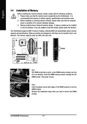
...the direction. It is recommended that the computer power is supported by the motherboard. The motherboard supports DDR II memory modules, whereby BIOS will automatically detect memory capacity and specifications. Reverse the installation steps when you are designed so that the memory used . 2. The... 1-4 Installation of the DIMM sockets to lock the DIMM module. A memory module can differ with the following conditions: 1. GA-8I945GMF Motherboard - 14 - Memory modules are unable to remove the DIMM module. Insert the DIMM memory module vertically into the DIMM socket.
...the direction. It is recommended that the computer power is supported by the motherboard. The motherboard supports DDR II memory modules, whereby BIOS will automatically detect memory capacity and specifications. Reverse the installation steps when you are designed so that the memory used . 2. The... 1-4 Installation of the DIMM sockets to lock the DIMM module. A memory module can differ with the following conditions: 1. GA-8I945GMF Motherboard - 14 - Memory modules are unable to remove the DIMM module. Insert the DIMM memory module vertically into the DIMM socket.
Manual
Page 15
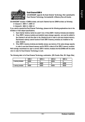
... two DDR II memory modules are installed, please use memory of the same storage capacity in order to detect all the DDR II memory modules. GA-8I945GMF includes 4 DIMM sockets, and each Channel has two DIMM sockets as following: Channel A : DDR II 1, DDR II 2 Channel B : DDR... table is for BIOS to use dual channel memory. Hardware Installation Dual channel memory cannot function if both DDR II memory modules are installed. 2. After operating the Dual Channel Technology, the bandwidth of Intel chipset specifications. 1. English Dual Channel DDR II GA-8I945GMF supports the Dual ...
... two DDR II memory modules are installed, please use memory of the same storage capacity in order to detect all the DDR II memory modules. GA-8I945GMF includes 4 DIMM sockets, and each Channel has two DIMM sockets as following: Channel A : DDR II 1, DDR II 2 Channel B : DDR... table is for BIOS to use dual channel memory. Hardware Installation Dual channel memory cannot function if both DDR II memory modules are installed. 2. After operating the Dual Channel Technology, the bandwidth of Intel chipset specifications. 1. English Dual Channel DDR II GA-8I945GMF supports the Dual ...
Manual
Page 16
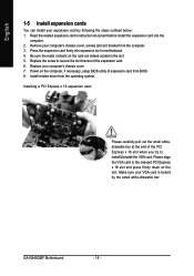
... card. Power on the computer, if necessary, setup BIOS utility of expansion card from the computer. 3. Installing a PCI Express x 16 expansion card: Please carefully pull out the small whitedrawable bar at the end of the expansion card. 6. Install related driver from the operating system. GA-8I945GMF Motherboard - 16 - Be sure the metal contacts...
... card. Power on the computer, if necessary, setup BIOS utility of expansion card from the computer. 3. Installing a PCI Express x 16 expansion card: Please carefully pull out the small whitedrawable bar at the end of the expansion card. 6. Install related driver from the operating system. GA-8I945GMF Motherboard - 16 - Be sure the metal contacts...
Manual
Page 21
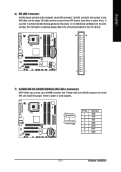
... 1 GND 7 1 2 TXP 3 TXN 1 7 4 GND 5 RXN 6 RXP 7 GND - 21 - English 6) IDE (IDE Connector) An IDE device connects to work properly. Hardware Installation Please refer to the BIOS setting for information on settings, please refer to the instructions located on one IDE cable, and the single IDE cable can provide up to two...
... 1 GND 7 1 2 TXP 3 TXN 1 7 4 GND 5 RXN 6 RXP 7 GND - 21 - English 6) IDE (IDE Connector) An IDE device connects to work properly. Hardware Installation Please refer to the BIOS setting for information on settings, please refer to the instructions located on one IDE cable, and the single IDE cable can provide up to two...
Manual
Page 26
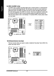
... connector will make the device unable to enable or disable the "Case Open" item in BIOS, if the system case begin remove. Check the pin assignment carefully while you connect the SPDIF_IO cable. Definition 1 1 Signal 2 GND GA-8I945GMF Motherboard - 26 - Use SPDIF IN feature only when your stereo system has digital input function...
... connector will make the device unable to enable or disable the "Case Open" item in BIOS, if the system case begin remove. Check the pin assignment carefully while you connect the SPDIF_IO cable. Definition 1 1 Signal 2 GND GA-8I945GMF Motherboard - 26 - Use SPDIF IN feature only when your stereo system has digital input function...
Manual
Page 29
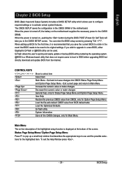
... necessary power to its original settings. Status Page Setup Menu / Option Page Setup Menu Press F1 to a new BIOS, either Gigabyte's Q-Flash or @BIOS utility can enter the BIOS setup screen by pressing "Ctrl + F1". The CMOS SETUP saves the configuration in the event that does not require... users to boot to DOS before upgrading BIOS but directly download and update BIOS from BIOS default table Load the Optimized Defaults ...
... necessary power to its original settings. Status Page Setup Menu / Option Page Setup Menu Press F1 to a new BIOS, either Gigabyte's Q-Flash or @BIOS utility can enter the BIOS setup screen by pressing "Ctrl + F1". The CMOS SETUP saves the configuration in the event that does not require... users to boot to DOS before upgrading BIOS but directly download and update BIOS from BIOS default table Load the Optimized Defaults ...
Manual
Page 30
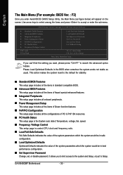
...; Set Supervisor Password Change, set, or disable password. English The Main Menu (For example: BIOS Ver. : F2) Once you enter Award BIOS CMOS Setup Utility, the Main Menu (as usual. GA-8I945GMF Motherboard - 30 - Use arrow keys to select among the items and press to the default ...for stability. „ Standard CMOS Features This setup page includes all the items in standard compatible BIOS. „ Advanced BIOS Features This setup page includes ...
...; Set Supervisor Password Change, set, or disable password. English The Main Menu (For example: BIOS Ver. : F2) Once you enter Award BIOS CMOS Setup Utility, the Main Menu (as usual. GA-8I945GMF Motherboard - 30 - Use arrow keys to select among the items and press to the default ...for stability. „ Standard CMOS Features This setup page includes all the items in standard compatible BIOS. „ Advanced BIOS Features This setup page includes ...

Manual
Page 31
BIOS Setup English „ Set User Password Change, set, or disable password. It allows you to limit access to the system. „ Save & Exit Setup Save CMOS value settings to CMOS and exit setup. „ Exit Without Saving Abandon all CMOS value changes and exit setup. - 31 -
BIOS Setup English „ Set User Password Change, set, or disable password. It allows you to limit access to the system. „ Save & Exit Setup Save CMOS value settings to CMOS and exit setup. „ Exit Without Saving Abandon all CMOS value changes and exit setup. - 31 -
Manual
Page 32
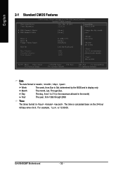
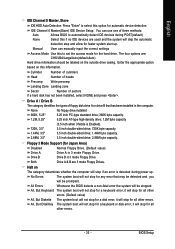
... month, Jan. Jan. Week The week, from 1999 through 2098 Time The times format in the month) < Ye a r > 1999 to Sat, determined by the BIOS and is , , , . GA-8I945GMF Motherboard - 32 - to Dec. 1 to 31 (or maximum allowed in . English 2-1 Standard CMOS Features Date (mm:dd:yy) Time (hh:mm:ss) CMOS Setup...
... month, Jan. Jan. Week The week, from 1999 through 2098 Time The times format in the month) < Ye a r > 1999 to Sat, determined by the BIOS and is , , , . GA-8I945GMF Motherboard - 32 - to Dec. 1 to 31 (or maximum allowed in . English 2-1 Standard CMOS Features Date (mm:dd:yy) Time (hh:mm:ss) CMOS Setup...
Manual
Page 33
... prompted. Drive A / Drive B The category identifies the types of sectors If a hard disk has not been installed, select NONE and press . All Errors Whenever the BIOS detects a non-fatal error the system will stop for the hard drive. Manual User can use one of three methods: Auto Allows... BIOS to set the access mode for all other errors. (Default value) All, But Diskette The system boot will skip the automatic detection step and allow ...
... prompted. Drive A / Drive B The category identifies the types of sectors If a hard disk has not been installed, select NONE and press . All Errors Whenever the BIOS detects a non-fatal error the system will stop for the hard drive. Manual User can use one of three methods: Auto Allows... BIOS to set the access mode for all other errors. (Default value) All, But Diskette The system boot will skip the automatic detection step and allow ...
Manual
Page 34
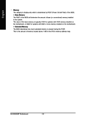
GA-8I945GMF Motherboard - 34 - The value of the base memory is determined by POST (Power On Self Test) of the BIOS. English Memory The category is display-only which is typically 512K for systems with 512K memory installed on the motherboard, or 640K for systems with ...640K or more memory installed on the motherboard. Extended Memory The BIOS determines how much extended memory is the amount of base (or conventional) memory installed in the CPU's memory address map. Base Memory The POST of...
GA-8I945GMF Motherboard - 34 - The value of the base memory is determined by POST (Power On Self Test) of the BIOS. English Memory The category is display-only which is typically 512K for systems with 512K memory installed on the motherboard, or 640K for systems with ...640K or more memory installed on the motherboard. Extended Memory The BIOS determines how much extended memory is the amount of base (or conventional) memory installed in the CPU's memory address map. Base Memory The POST of...
Manual
Page 35
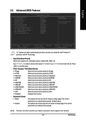
... Select your boot device priority by USB-ZIP. USB-CDROM Select your boot device priority by USB-CDROM. Disabled Disabled this menu. BIOS Setup First / Second / Third Boot Device Floppy Select your boot device priority by Floppy. LS120 Select your boot device priority by...-on cards) SCSI, RAID, etc. LAN Select your boot device priority by LAN. English 2-2 Advanced BIOS Features CMOS Setup Utility-Copyright (C) 1984-2005 Award Software Advanced BIOS Features ` Hard Disk Boot Priority First Boot Device Second Boot Device Third Boot Device Password Check # CPU...
... Select your boot device priority by USB-ZIP. USB-CDROM Select your boot device priority by USB-CDROM. Disabled Disabled this menu. BIOS Setup First / Second / Third Boot Device Floppy Select your boot device priority by Floppy. LS120 Select your boot device priority by...-on cards) SCSI, RAID, etc. LAN Select your boot device priority by LAN. English 2-2 Advanced BIOS Features CMOS Setup Utility-Copyright (C) 1984-2005 Award Software Advanced BIOS Features ` Hard Disk Boot Priority First Boot Device Second Boot Device Third Boot Device Password Check # CPU...
Manual
Page 37
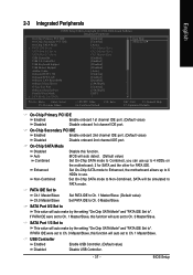
...-Chip SATA mode to Enhanced, the motherboard allows up to PATA mode. USB Controller Enabled Enable USB Controller. (Default value) Disabled Disable USB Controller. - 37 - BIOS will be simulated to 4 HDDs on the motherboard; 2 for SATA and the other for PATA IDE. English 2-3 Integrated Peripherals CMOS Setup Utility-Copyright (C) 1984-2004... IDE On-Chip Secondary PCI IDE On-Chip SATA Mode x PATA IDE Set to SATA Port 0/2 Set to SATA Port 1/3 Set to Ch. 0 Master/Slave. BIOS Setup
...-Chip SATA mode to Enhanced, the motherboard allows up to PATA mode. USB Controller Enabled Enable USB Controller. (Default value) Disabled Disable USB Controller. - 37 - BIOS will be simulated to 4 HDDs on the motherboard; 2 for SATA and the other for PATA IDE. English 2-3 Integrated Peripherals CMOS Setup Utility-Copyright (C) 1984-2004... IDE On-Chip Secondary PCI IDE On-Chip SATA Mode x PATA IDE Set to SATA Port 0/2 Set to SATA Port 1/3 Set to Ch. 0 Master/Slave. BIOS Setup
Manual
Page 38
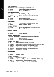
... is 3BC/IRQ7. USB Keyboard Support Enabled Disabled Enable USB Keyboard Support. Enable onboard LPT port and address is 2E8/IRQ3. GA-8I945GMF Motherboard - 38 - Disable USB Keyboard Support. (Default value) USB Mouse Support Enabled Enable USB Mouse Support. Disabled Disable USB...G-Keyless Port Enabled Enable G-Keyless port function. (Default value) Disabled Disable this function. (Default value) Onboard Serial Port 1 Auto BIOS will automatically setup the port 1 address. 3F8/IRQ4 2F8/IRQ3 Enable onboard Serial port 1 and address is 3F8/IRQ4. (Default value...
... is 3BC/IRQ7. USB Keyboard Support Enabled Disabled Enable USB Keyboard Support. Enable onboard LPT port and address is 2E8/IRQ3. GA-8I945GMF Motherboard - 38 - Disable USB Keyboard Support. (Default value) USB Mouse Support Enabled Enable USB Mouse Support. Disabled Disable USB...G-Keyless Port Enabled Enable G-Keyless port function. (Default value) Disabled Disable this function. (Default value) Onboard Serial Port 1 Auto BIOS will automatically setup the port 1 address. 3F8/IRQ4 2F8/IRQ3 Enable onboard Serial port 1 and address is 3F8/IRQ4. (Default value...


