
Manual
Page 4
Table of Contents GA-8I945GMBX Motherboard Layout 6 Block Diagram ...7 Chapter 1 Hardware Installation 9 1-1 Considerations Prior to Installation 9 1-2 Feature Summary 10 1-3 Installation of the CPU and Heatsink 12 1-3-1 Installation of the CPU 12 1-3-2 Installation of the Fan Heatsink 13 1-4 Installation of Memory 14 1-5 Installation of Expansion Cards 16 1-6 I/O Back Panel Introduction 17 1-7 Connectors Introduction 18 Chapter 2 BIOS...
Table of Contents GA-8I945GMBX Motherboard Layout 6 Block Diagram ...7 Chapter 1 Hardware Installation 9 1-1 Considerations Prior to Installation 9 1-2 Feature Summary 10 1-3 Installation of the CPU and Heatsink 12 1-3-1 Installation of the CPU 12 1-3-2 Installation of the Fan Heatsink 13 1-4 Installation of Memory 14 1-5 Installation of Expansion Cards 16 1-6 I/O Back Panel Introduction 17 1-7 Connectors Introduction 18 Chapter 2 BIOS...

Manual
Page 9
... to be an unofficial Gigabyte product. - 9 - When handling the motherboard, avoid touching any installation steps or have these items on the motherboard. Installation Notices 1. Before using the product, please verify that the power supply is best to wear an electrostatic discharge (ESD) cuff when handling electronic components (CPU, RAM). 4. Damage as a result...
... to be an unofficial Gigabyte product. - 9 - When handling the motherboard, avoid touching any installation steps or have these items on the motherboard. Installation Notices 1. Before using the product, please verify that the power supply is best to wear an electrostatic discharge (ESD) cuff when handling electronic components (CPU, RAM). 4. Damage as a result...

Manual
Page 10
GA-8I945GMBX Motherboard - 10 - For example, 4 GB of memory is reserved for system usage and therefore the actual memory size is less than the stated amount. English 1-2 Feature Summary CPU Š Š Š Chipset Š Š Š Memory Š Š Š Slots Š Š Š IDE Connections ... (10/100/1000 Mbit) 1 RJ 45 port Supported on the Win 2000/XP operating systems (Note 1) For further CPU support information, please go to GIGABYTE's website. (Note 2) Due to standard PC architecture, a certain amount of memory size will instead be shown as 3....
GA-8I945GMBX Motherboard - 10 - For example, 4 GB of memory is reserved for system usage and therefore the actual memory size is less than the stated amount. English 1-2 Feature Summary CPU Š Š Š Chipset Š Š Š Memory Š Š Š Slots Š Š Š IDE Connections ... (10/100/1000 Mbit) 1 RJ 45 port Supported on the Win 2000/XP operating systems (Note 1) For further CPU support information, please go to GIGABYTE's website. (Note 2) Due to standard PC architecture, a certain amount of memory size will instead be shown as 3....

Manual
Page 11
... SPDIF Out connection CD In connection Supported on the Win 2000/XP operating systems IT8712 System voltage detection CPU / System temperature detection CPU / System fan speed detection CPU / System warning temperature CPU / System fan failure warning CPU / System smart fan control Onboard Intel® ICH7R chipset supports data striping (RAID 0), mirroring (RAID 1), striping + mirroring (RAID...
... SPDIF Out connection CD In connection Supported on the Win 2000/XP operating systems IT8712 System voltage detection CPU / System temperature detection CPU / System fan speed detection CPU / System warning temperature CPU / System fan failure warning CPU / System smart fan control Onboard Intel® ICH7R chipset supports data striping (RAID 0), mirroring (RAID 1), striping + mirroring (RAID...
Manual
Page 12
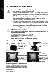
... of Hyper-Threading Technology for the peripherals. Fig. 4 Once the CPU is installed on the CPU socket to the CPU during installation.) GA-8I945GMBX Motherboard - 12 - OS: An operation system that the system bus frequency be set the CPU host frequency in the wrong direction, the CPU will not insert properly. Align the indented corner of the...
... of Hyper-Threading Technology for the peripherals. Fig. 4 Once the CPU is installed on the CPU socket to the CPU during installation.) GA-8I945GMBX Motherboard - 12 - OS: An operation system that the system bus frequency be set the CPU host frequency in the wrong direction, the CPU will not insert properly. Align the indented corner of the...

Manual
Page 13
... fan heatsink. - 13 - To prevent such an occurrence, it onto the motherboard. Align the fan heatsink with screws. The fan heatsink may adhere to the CPU fan header located on the surface of the thermal paste. Hardware Installation Assure that either thermal tape rather than thermal paste be used for your... fan heatsink.) Fig.4 Finally, please attach the power connector of the fan heatsink to the CPU as a result of hardening of the installed CPU. Fig.2 Install the motherboard in the chassis.
... fan heatsink. - 13 - To prevent such an occurrence, it onto the motherboard. Align the fan heatsink with screws. The fan heatsink may adhere to the CPU fan header located on the surface of the thermal paste. Hardware Installation Assure that either thermal tape rather than thermal paste be used for your... fan heatsink.) Fig.4 Finally, please attach the power connector of the fan heatsink to the CPU as a result of hardening of the installed CPU. Fig.2 Install the motherboard in the chassis.

Manual
Page 19
... a system that does not provide the required power, the result can withstand high power consumption be used (300W or greater). It is unable to the CPU. Please use a 24-pin ATX power supply, please remove the small cover on the power connector on the motherboard before plugging in the power cord...
... a system that does not provide the required power, the result can withstand high power consumption be used (300W or greater). It is unable to the CPU. Please use a 24-pin ATX power supply, please remove the small cover on the power connector on the motherboard before plugging in the power cord...

Manual
Page 20
...of the cable connects to the FDD drive. Please remember to connect the power to the cooler to the pin1 position. 2 34 1 33 GA-8I945GMBX Motherboard - 20 - Please connect the red power connector wire to prevent system overheating and failure. A red power connector wire indicates a positive ...pin(only for CPU_FAN) 5) FDD (FDD Connector) The FDD connector is the ground wire (GND). Please remember to connect the power to the CPU fan to prevent CPU overheating and failure. 1 CPU_FAN 1 SYS_FAN Pin No. 1 2 3 4 Definition GND +12V Sense Speed Control (Only for CPU_FAN) power connector ...
...of the cable connects to the FDD drive. Please remember to connect the power to the cooler to the pin1 position. 2 34 1 33 GA-8I945GMBX Motherboard - 20 - Please connect the red power connector wire to prevent system overheating and failure. A red power connector wire indicates a positive ...pin(only for CPU_FAN) 5) FDD (FDD Connector) The FDD connector is the ground wire (GND). Please remember to connect the power to the CPU fan to prevent CPU overheating and failure. 1 CPU_FAN 1 SYS_FAN Pin No. 1 2 3 4 Definition GND +12V Sense Speed Control (Only for CPU_FAN) power connector ...

Manual
Page 30
Please Load Optimized Defaults in safe configuration. GA-8I945GMBX Motherboard - 30 - CMOS Setup Utility-Copyright (C) 1984-2005 Award Software ` Standard CMOS Features ` Advanced BIOS Features ` Integrated Peripherals ` Power Management Setup ` PnP/PCI Configurations ` PC .... „ PC Health Status This setup page is the System auto detect Temperature, voltage, fan, speed. „ Frequency/Voltage Control This setup page is control CPU clock and frequency ratio. „ Load Fail-Safe Defaults Fail-Safe Defaults indicates the value of the system parameters which the system would be in...
Please Load Optimized Defaults in safe configuration. GA-8I945GMBX Motherboard - 30 - CMOS Setup Utility-Copyright (C) 1984-2005 Award Software ` Standard CMOS Features ` Advanced BIOS Features ` Integrated Peripherals ` Power Management Setup ` PnP/PCI Configurations ` PC .... „ PC Health Status This setup page is the System auto detect Temperature, voltage, fan, speed. „ Frequency/Voltage Control This setup page is control CPU clock and frequency ratio. „ Load Fail-Safe Defaults Fail-Safe Defaults indicates the value of the system parameters which the system would be in...

Manual
Page 33
... Normal Floppy Drive. (Default value) Drive A Drive B Both Drive A is present during power up. Drive B is the amount of memory located above 1 MB in the CPU's memory address map. All, But Disk/Key The system boot will not stop for all other errors. Memory The category is display-only which is...
... Normal Floppy Drive. (Default value) Drive A Drive B Both Drive A is present during power up. Drive B is the amount of memory located above 1 MB in the CPU's memory address map. All, But Disk/Key The system boot will not stop for all other errors. Memory The category is display-only which is...

Manual
Page 34
...Disk Select your boot device priority by Hard Disk. USB-CDROM Select your boot device priority by USB-CDROM. Disabled Disabled this function. GA-8I945GMBX Motherboard - 34 - to Setup page if the correct password is not entered at the prompt. (Default value) System The system will...-2005 Award Software Advanced BIOS Features ` Hard Disk Boot Priority First Boot Device Second Boot Device Third Boot Device Password Check # CPU Hyper-Threading Limit CPUID Max. USB-FDD Select your boot device priority by USB-FDD. LAN Select your boot device priority by LAN...
...Disk Select your boot device priority by Hard Disk. USB-CDROM Select your boot device priority by USB-CDROM. Disabled Disabled this function. GA-8I945GMBX Motherboard - 34 - to Setup page if the correct password is not entered at the prompt. (Default value) System The system will...-2005 Award Software Advanced BIOS Features ` Hard Disk Boot Priority First Boot Device Second Boot Device Third Boot Device Password Check # CPU Hyper-Threading Limit CPUID Max. USB-FDD Select your boot device priority by USB-FDD. LAN Select your boot device priority by LAN...

Manual
Page 35
... operating system with multi processors mode supported. (Default value) Disables CPU Hyper Threading. CPU EIST Function (Note) Enabled Enable CPU EIST function. (Default value) Disabled Disable EIST function. BIOS Setup CPU Enhanced Halt (C1E) (Note) Enabled Disabled Enable CPU Enhanced Halt (C1E) function. (Default value) Disable CPU Enhanced Halt (C1E) function. ASF Support Enabled Disabled Enable...
... operating system with multi processors mode supported. (Default value) Disables CPU Hyper Threading. CPU EIST Function (Note) Enabled Enable CPU EIST function. (Default value) Disabled Disable EIST function. BIOS Setup CPU Enhanced Halt (C1E) (Note) Enabled Disabled Enable CPU Enhanced Halt (C1E) function. (Default value) Disable CPU Enhanced Halt (C1E) function. ASF Support Enabled Disabled Enable...

Manual
Page 42
...". If the case have been opened, "Case Opened" will restart. CPU Warning Temperature 60oC / 140oF Monitor CPU temperature at 60oC / 140oF. 70oC / 158oF Monitor CPU temperature at 70oC / 158oF. 80oC / 176oF Monitor CPU temperature at 80oC / 176oF. 90oC / 194oF Disabled Monitor CPU temperature at next boot. GA-8I945GMBX Motherboard - 42 - Current Voltage(V) Vcore / DDRV / +3.3V / +12V Detect...
...". If the case have been opened, "Case Opened" will restart. CPU Warning Temperature 60oC / 140oF Monitor CPU temperature at 60oC / 140oF. 70oC / 158oF Monitor CPU temperature at 70oC / 158oF. 80oC / 176oF Monitor CPU temperature at 80oC / 176oF. 90oC / 194oF Disabled Monitor CPU temperature at next boot. GA-8I945GMBX Motherboard - 42 - Current Voltage(V) Vcore / DDRV / +3.3V / +12V Detect...

Manual
Page 43
... with Easy Tune based on System temperature. (Default value) - 43 - Auto BIOS autodetects the type of CPU fan you use a CPU fan with a 3-pin fan power cable. Note: In fact, the Voltage option can adjust the fan speed with 3-pin or 4-pin power cables. Users... can be used for it. (Default value) Voltage Set to PWM when you use a CPU fan with a 4-pin fan power cable. Enabled When this function is enabled. However, some 4-pin CPU fan power cables are not designed following Intel 4-Wire fans PWM control specifications. BIOS Setup English...
... with Easy Tune based on System temperature. (Default value) - 43 - Auto BIOS autodetects the type of CPU fan you use a CPU fan with a 3-pin fan power cable. Note: In fact, the Voltage option can adjust the fan speed with 3-pin or 4-pin power cables. Users... can be used for it. (Default value) Voltage Set to PWM when you use a CPU fan with a 4-pin fan power cable. Enabled When this function is enabled. However, some 4-pin CPU fan power cables are not designed following Intel 4-Wire fans PWM control specifications. BIOS Setup English...
Manual
Page 44
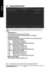
...66 Memory Frequency = Host clock x 2.66. 3.33 Memory Frequency = Host clock x 3.33. GA-8I945GMBX Motherboard - 44 - English 2-7 Frequency/Voltage Control CMOS Setup Utility-Copyright (C) 1984-2005 Award Software Frequency/Voltage Control CPU Clock Ratio System Memory Multiplier Memory Frequency (Mhz) [16X] [Auto] 533 Item Help Menu Level`... Set CPU Ratio if CPU Ratio is not changeable. For power end-user use only. CPU Clock Ratio (Note) This setup option will display "Locked" and read only if the CPU ratio is unclocked KLJI: Move Enter: Select F5:...
...66 Memory Frequency = Host clock x 2.66. 3.33 Memory Frequency = Host clock x 3.33. GA-8I945GMBX Motherboard - 44 - English 2-7 Frequency/Voltage Control CMOS Setup Utility-Copyright (C) 1984-2005 Award Software Frequency/Voltage Control CPU Clock Ratio System Memory Multiplier Memory Frequency (Mhz) [16X] [Auto] 533 Item Help Menu Level`... Set CPU Ratio if CPU Ratio is not changeable. For power end-user use only. CPU Clock Ratio (Note) This setup option will display "Locked" and read only if the CPU ratio is unclocked KLJI: Move Enter: Select F5:...

Manual
Page 53
... feature that allows system hardware information such as CPU, memory, graphics card, etc. Through GIGABYTE M.I .B. 2 features. M.I.B.2 (Memory Intelligent Booster 2) Built on the original M.I.B., the new Memory Intelligent Booster 2 (M.I .T.) allows user to the CPU for solid system stability. S.O.S. (System Overclock ...up errors resulting from system over-enhancement by selecting from a recommended memory module list. C.I.A.2 (CPU Intelligent Accelerator 2) GIGABYTE CPU Intelligent Accelerator 2(C.I .T.'s integration of the user PC and provides the user with relative speed and...
... feature that allows system hardware information such as CPU, memory, graphics card, etc. Through GIGABYTE M.I .B. 2 features. M.I.B.2 (Memory Intelligent Booster 2) Built on the original M.I.B., the new Memory Intelligent Booster 2 (M.I .T.) allows user to the CPU for solid system stability. S.O.S. (System Overclock ...up errors resulting from system over-enhancement by selecting from a recommended memory module list. C.I.A.2 (CPU Intelligent Accelerator 2) GIGABYTE CPU Intelligent Accelerator 2(C.I .T.'s integration of the user PC and provides the user with relative speed and...

Manual
Page 54
...GIGABYTE website Display EasyTuneTM 5 Help file Quit or Minimize EasyTuneTM 5 software (Note) EasyTune 5 functions may vary depending on to use tools such as 1) Overclocking for monitoring system status.(Note) User Interface Overview Button / Display 1. GA-8I945GMBX Motherboard - 54 - for special enhancement for CPU... and Memory, 3) Smart-Fan control for managing fan speed control of CPU frequency Shows the current functions status Log on different motherboards...
...GIGABYTE website Display EasyTuneTM 5 Help file Quit or Minimize EasyTuneTM 5 software (Note) EasyTune 5 functions may vary depending on to use tools such as 1) Overclocking for monitoring system status.(Note) User Interface Overview Button / Display 1. GA-8I945GMBX Motherboard - 54 - for special enhancement for CPU... and Memory, 3) Smart-Fan control for managing fan speed control of CPU frequency Shows the current functions status Log on different motherboards...


