Manual
Page 4
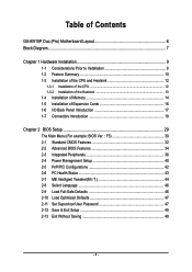
...GA-8I915P Duo (Pro) Motherboard Layout 6 Block Diagram ...7 Chapter 1 Hardware Installation 9 1-1 Considerations Prior to Installation 9 1-2 Feature Summary 10 1-3 Installation of the CPU and Heatsink 12 1-3-1 Installation of the CPU 12 1-3-2 Installation of the Heatsink 13 1-4 Installation of Memory 14 1-5 Installation of Expansion Cards 16 1-6 I/O Back Panel Introduction 17 1-7 Connectors Introduction 18 Chapter 2 BIOS... Setup 29 The Main Menu (For example: BIOS Ver. : F5 30 2-1 Standard CMOS Features 32 2-2 Advanced BIOS Features 34 2-3 Integrated...
...GA-8I915P Duo (Pro) Motherboard Layout 6 Block Diagram ...7 Chapter 1 Hardware Installation 9 1-1 Considerations Prior to Installation 9 1-2 Feature Summary 10 1-3 Installation of the CPU and Heatsink 12 1-3-1 Installation of the CPU 12 1-3-2 Installation of the Heatsink 13 1-4 Installation of Memory 14 1-5 Installation of Expansion Cards 16 1-6 I/O Back Panel Introduction 17 1-7 Connectors Introduction 18 Chapter 2 BIOS... Setup 29 The Main Menu (For example: BIOS Ver. : F5 30 2-1 Standard CMOS Features 32 2-2 Advanced BIOS Features 34 2-3 Integrated...
Manual
Page 5
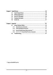
Chapter 3 Install Drivers 49 3-1 Install Chipset Drivers 49 3-2 Software Applications 50 3-3 Driver CD Information 50 3-4 Hardware Information 51 3-5 Contact Us ...51 Chapter 4 Appendix 53 4-1 Unique Software Utilities 53 4-1-1 Xpress Recovery Introduction 54 4-1-2 Flash BIOS Method Introduction 57 4-1-3 Serial ATA BIOS Setting Utility Introduction 68 4-1-4 2 / 4 / 5.1 / 7.1 Channel Audio Function Introduction 75 4-2 Troubleshooting 81 Only for GA-8I915P Duo Pro. - 5 -
Chapter 3 Install Drivers 49 3-1 Install Chipset Drivers 49 3-2 Software Applications 50 3-3 Driver CD Information 50 3-4 Hardware Information 51 3-5 Contact Us ...51 Chapter 4 Appendix 53 4-1 Unique Software Utilities 53 4-1-1 Xpress Recovery Introduction 54 4-1-2 Flash BIOS Method Introduction 57 4-1-3 Serial ATA BIOS Setting Utility Introduction 68 4-1-4 2 / 4 / 5.1 / 7.1 Channel Audio Function Introduction 75 4-2 Troubleshooting 81 Only for GA-8I915P Duo Pro. - 5 -
Manual
Page 6
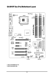
Only for GA-8I915P Duo Pro. GA-8I915P Duo (Pro) Motherboard Layout DDRII_2 DDRII_1 DDR1 DDR2 PWR_FAN KB_MS ATX_12V LGA775 ATX SPDIF_O SPDIF_I CPU_FAN COMA LPT IDE1 GA-8I915P Duo (Pro) USB USB LAN2 LAN1 AUDIO1 AUDIO2 CD_IN AZALIA_FP Broadcom 5751 /5789 NB_FAN Broadcom 5751/5789 PCIE_1 CODEC PCIE_2 IT8712 IR Intel 915P PCIE_16 CLR_CMOS SYS_FAN Main BIOS Backup BIOS BAT PCI1 PCI2 TSB43AB23 PCI3 F1_1394 ICH6 / ICH6R S_ATA3 S_ATA2 S_ATA1 S_ATA0 VT6410 IDE3 FDD F_USB2 F_PANEL F_USB1 IDE2 F2_1394 PWR_LED Only for GA-8I915P Duo. - 6 -
Only for GA-8I915P Duo Pro. GA-8I915P Duo (Pro) Motherboard Layout DDRII_2 DDRII_1 DDR1 DDR2 PWR_FAN KB_MS ATX_12V LGA775 ATX SPDIF_O SPDIF_I CPU_FAN COMA LPT IDE1 GA-8I915P Duo (Pro) USB USB LAN2 LAN1 AUDIO1 AUDIO2 CD_IN AZALIA_FP Broadcom 5751 /5789 NB_FAN Broadcom 5751/5789 PCIE_1 CODEC PCIE_2 IT8712 IR Intel 915P PCIE_16 CLR_CMOS SYS_FAN Main BIOS Backup BIOS BAT PCI1 PCI2 TSB43AB23 PCI3 F1_1394 ICH6 / ICH6R S_ATA3 S_ATA2 S_ATA1 S_ATA0 VT6410 IDE3 FDD F_USB2 F_PANEL F_USB1 IDE2 F2_1394 PWR_LED Only for GA-8I915P Duo. - 6 -
Manual
Page 7
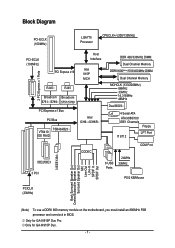
Only for GA-8I915P Duo. - 7 - Only for GA-8I915P Duo Pro. Block Diagram PCI-ECLK (100MHz) LGA775 Processor CPUCLK+/-(200/133MHz) PCI-ECLK (100MHz) PCI Express x16 Host Interface Intel 915P MCH 2 .../333MHz DIMM Dual Channel Memory DDRII 600(Note)/533/400MHz DIMM Dual Channel Memory MCHCLK (133/200MHz) 66MHz 33MHz 14.318MHz 48MHz Dual BIOS 4 Serial ATA ATA33/66/100 IDE1 Channels Floppy IT 8712 LPT Port IDE2/IDE3 3 PCI CODEC COM Port 8 USB Ports 24MHz ...Note) To use a DDRII 600 memory module on the motherboard, you must install an 800MHz FSB processor and overclock in BIOS.
Only for GA-8I915P Duo. - 7 - Only for GA-8I915P Duo Pro. Block Diagram PCI-ECLK (100MHz) LGA775 Processor CPUCLK+/-(200/133MHz) PCI-ECLK (100MHz) PCI Express x16 Host Interface Intel 915P MCH 2 .../333MHz DIMM Dual Channel Memory DDRII 600(Note)/533/400MHz DIMM Dual Channel Memory MCHCLK (133/200MHz) 66MHz 33MHz 14.318MHz 48MHz Dual BIOS 4 Serial ATA ATA33/66/100 IDE1 Channels Floppy IT 8712 LPT Port IDE2/IDE3 3 PCI CODEC COM Port 8 USB Ports 24MHz ...Note) To use a DDRII 600 memory module on the motherboard, you must install an 800MHz FSB processor and overclock in BIOS.

Manual
Page 10
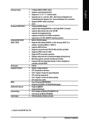
Only for GA-8I915P Duo. Only for GA-8I915P Duo Pro. GA-8I915P Duo (Pro) Motherboard - 10 - English 1-2 Feature Summary CPU Chipset Memory Slots IDE Connections FDD Connections Onboard SATA Peripherals Onboard LAN Š Supports the latest Intel® Pentium&#...; 2 RJ 45 port--LAN1 / LAN2 (Note) To use a DDRII 600 memory module on the motherboard, you must install an 800MHz FSB processor and overclock in BIOS.
Only for GA-8I915P Duo. Only for GA-8I915P Duo Pro. GA-8I915P Duo (Pro) Motherboard - 10 - English 1-2 Feature Summary CPU Chipset Memory Slots IDE Connections FDD Connections Onboard SATA Peripherals Onboard LAN Š Supports the latest Intel® Pentium&#...; 2 RJ 45 port--LAN1 / LAN2 (Note) To use a DDRII 600 memory module on the motherboard, you must install an 800MHz FSB processor and overclock in BIOS.
Manual
Page 11
...; CPU smart fan control Š Use of licensed AWARD BIOS Š Supports Dual BIOS /Q-Flash/Multilanguage Š Supports @BIOS Š Supports EasyTune Š Over Voltage via BIOS (CPU/DDR/PCI-E) Š Over Clock via BIOS (CPU/DDR) Š ATX form factor; 30.5cm x 24.4cm Only for GA-8I915P Duo Pro. - 11 - Hardware Installation Center/Subwoofer Speaker Out ; Back...
...; CPU smart fan control Š Use of licensed AWARD BIOS Š Supports Dual BIOS /Q-Flash/Multilanguage Š Supports @BIOS Š Supports EasyTune Š Over Voltage via BIOS (CPU/DDR/PCI-E) Š Over Clock via BIOS (CPU/DDR) Š ATX form factor; 30.5cm x 24.4cm Only for GA-8I915P Duo Pro. - 11 - Hardware Installation Center/Subwoofer Speaker Out ; Back...
Manual
Page 12
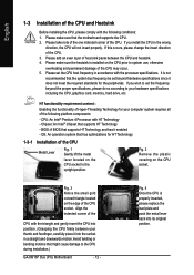
... CPU. HT functionality requirement content : Enabling the functionality of Hyper-Threading Technology for the peripherals. BIOS: A BIOS that the system bus frequency be set beyond the proper specifications, please do so according to the CPU during installation.) GA-8I915P Duo (Pro) Motherboard - 12 - Align the indented corner of the CPU with the triangle and gently insert...
... CPU. HT functionality requirement content : Enabling the functionality of Hyper-Threading Technology for the peripherals. BIOS: A BIOS that the system bus frequency be set beyond the proper specifications, please do so according to the CPU during installation.) GA-8I915P Duo (Pro) Motherboard - 12 - Align the indented corner of the CPU with the triangle and gently insert...
Manual
Page 14
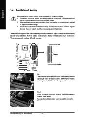
A memory module can differ with the following conditions: 1. The motherboard supports DDR II & DDR memory modules, whereby BIOS will automatically detect memory capacity and specifications. English 1-4 Installation of Memory Before installing the memory modules, please comply with each slot....memory module vertically into the DIMM socket. Memory modules have a foolproof insertion design. Memory modules are unable to lock the DIMM module. GA-8I915P Duo (Pro) Motherboard - 14 - Please make sure that the computer power is recommended that they can only fit in one direction.
A memory module can differ with the following conditions: 1. The motherboard supports DDR II & DDR memory modules, whereby BIOS will automatically detect memory capacity and specifications. English 1-4 Installation of Memory Before installing the memory modules, please comply with each slot....memory module vertically into the DIMM socket. Memory modules have a foolproof insertion design. Memory modules are unable to lock the DIMM module. GA-8I915P Duo (Pro) Motherboard - 14 - Please make sure that the computer power is recommended that they can only fit in one direction.
Manual
Page 16
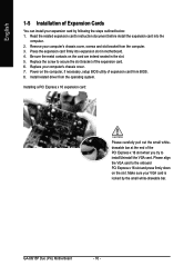
...your VGA card is locked by following the steps outlined below: 1. Be sure the metal contacts on the computer, if necessary, setup BIOS utility of the expansion card. 6. Remove your computer's chassis cover, screws and slot bracket from the operating system. Replace the screw ... the end of the PCI Express x 16 slot when you try to secure the slot bracket of expansion card from BIOS. 8. Replace your computer's chassis cover. 7. GA-8I915P Duo (Pro) Motherboard - 16 - Read the related expansion card's instruction document before install the expansion card into expansion slot in the...
...your VGA card is locked by following the steps outlined below: 1. Be sure the metal contacts on the computer, if necessary, setup BIOS utility of the expansion card. 6. Remove your computer's chassis cover, screws and slot bracket from the operating system. Replace the screw ... the end of the PCI Express x 16 slot when you try to secure the slot bracket of expansion card from BIOS. 8. Replace your computer's chassis cover. 7. GA-8I915P Duo (Pro) Motherboard - 16 - Read the related expansion card's instruction document before install the expansion card into expansion slot in the...
Manual
Page 22
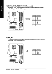
Pin No. GA-8I915P Duo (Pro) Motherboard - 22 - English 10) S_ATA0/S_ATA1/S_ATA2/S_ATA3 (Serial ATA Connector) Serial ATA can provide 150MB/s transfer rate. Definition 1 GND 7 1 2 TXP 3 TXN 4 GND 5 RXN 6 RXP 7 GND 11) PWR_LED PWR_LED is on/off. Definition 1 1 MPD+ 2 MPD- 3 MPD- Pin No. It will blink when the system enters suspend mode. Please refer to the BIOS setting for the Serial ATA and install the proper driver in order to indicate whether the system is connect with the system power indicator to work properly.
Pin No. GA-8I915P Duo (Pro) Motherboard - 22 - English 10) S_ATA0/S_ATA1/S_ATA2/S_ATA3 (Serial ATA Connector) Serial ATA can provide 150MB/s transfer rate. Definition 1 GND 7 1 2 TXP 3 TXN 4 GND 5 RXN 6 RXP 7 GND 11) PWR_LED PWR_LED is on/off. Definition 1 1 MPD+ 2 MPD- 3 MPD- Pin No. It will blink when the system enters suspend mode. Please refer to the BIOS setting for the Serial ATA and install the proper driver in order to indicate whether the system is connect with the system power indicator to work properly.
Manual
Page 24
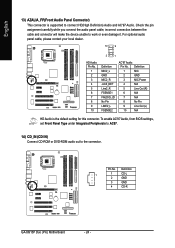
English 13) AZALIA_FP(Front Audio Panel Connector) This connector is the default setting for this connector. Definition 1 1 CD-L 2 GND 3 GND 4 CD-R GA-8I915P Duo (Pro) Motherboard - 24 - To enable AC'97 Audio, from BIOS settings, set Front Panel Type under Integrated Peripherals to AC97. 14) CD_IN (CD IN) Connect CD-ROM or DVD-ROM audio out...
English 13) AZALIA_FP(Front Audio Panel Connector) This connector is the default setting for this connector. Definition 1 1 CD-L 2 GND 3 GND 4 CD-R GA-8I915P Duo (Pro) Motherboard - 24 - To enable AC'97 Audio, from BIOS settings, set Front Panel Type under Integrated Peripherals to AC97. 14) CD_IN (CD IN) Connect CD-ROM or DVD-ROM audio out...
Manual
Page 29
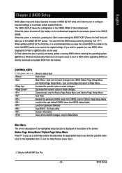
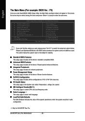
... system features. If you to use and the possible selections for GA-8I915P Duo Pro. - 29 - To exit the Help Window press . When the power is turned on -line description of the motherboard. Quit and not save the current BIOS to a disk in the CMOS SRAM of the highlighted setup function...Defaults Dual BIOS /Q-Flash utility System Information Save all the CMOS changes, only for Main Menu Main Menu The on , pushing the button during the BIOS POST (Power-On Self Test) will take you wish to upgrade to a new BIOS, either Gigabyte's Q-Flash or @BIOS utility can enter the BIOS setup ...
... system features. If you to use and the possible selections for GA-8I915P Duo Pro. - 29 - To exit the Help Window press . When the power is turned on -line description of the motherboard. Quit and not save the current BIOS to a disk in the CMOS SRAM of the highlighted setup function...Defaults Dual BIOS /Q-Flash utility System Information Save all the CMOS changes, only for Main Menu Main Menu The on , pushing the button during the BIOS POST (Power-On Self Test) will take you wish to upgrade to a new BIOS, either Gigabyte's Q-Flash or @BIOS utility can enter the BIOS setup ...
Manual
Page 30
... Optimized Defaults in safe configuration. This action makes the system reset to search the advanced option hidden. GA-8I915P Duo (Pro) Motherboard - 30 - If you can't find the setting you enter Award BIOS CMOS Setup Utility, the Main Menu (as usual. Use arrow keys to select among the items and... press to accept or enter the sub-menu. English The Main Menu (For example: BIOS Ver. : F5) Once you want, please press "Ctrl+F1" to the default for GA-8I915P Duo Pro. Only for stability. „ Standard CMOS Features This setup page includes all the items in standard...
... Optimized Defaults in safe configuration. This action makes the system reset to search the advanced option hidden. GA-8I915P Duo (Pro) Motherboard - 30 - If you can't find the setting you enter Award BIOS CMOS Setup Utility, the Main Menu (as usual. Use arrow keys to select among the items and... press to accept or enter the sub-menu. English The Main Menu (For example: BIOS Ver. : F5) Once you want, please press "Ctrl+F1" to the default for GA-8I915P Duo Pro. Only for stability. „ Standard CMOS Features This setup page includes all the items in standard...
Manual
Page 32
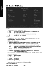
to Sat, determined by the BIOS and is , , , . Enter the appropriate option based on this if no IDE devices are : CHS/LBA/Large/Auto(... . Cylinder Number of cylinders Head Precomp Number of heads Write precomp Landing Zone Landing zone Sector Number of three methods: Auto Allows BIOS to 31 (or the maximum allowed in the month) Year The year, from 1 to automatically detect IDE devices during POST(default)...to Sat. The four options are used and the system will skip the automatic detection step and allow for GA-8I915P Duo Pro. GA-8I915P Duo (Pro) Motherboard - 32 -
to Sat, determined by the BIOS and is , , , . Enter the appropriate option based on this if no IDE devices are : CHS/LBA/Large/Auto(... . Cylinder Number of cylinders Head Precomp Number of heads Write precomp Landing Zone Landing zone Sector Number of three methods: Auto Allows BIOS to 31 (or the maximum allowed in the month) Year The year, from 1 to automatically detect IDE devices during POST(default)...to Sat. The four options are used and the system will skip the automatic detection step and allow for GA-8I915P Duo Pro. GA-8I915P Duo (Pro) Motherboard - 32 -
Manual
Page 34
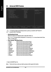
...device priority by USB-CDROM. USB-ZIP Select your boot device priority by Disabled. GA-8I915P Duo (Pro) Motherboard - 34 - Hard Disk Boot Priority Select boot sequence for GA-8I915P Duo Pro. (Note) This item will detect automatically and show up when you install a ...processor which supports this menu. First / Second / Third Boot Device Floppy Select your boot device priority by CDROM. Disabled Select your boot device priority by ZIP. English 2-2 Advanced BIOS...
...device priority by USB-CDROM. USB-ZIP Select your boot device priority by Disabled. GA-8I915P Duo (Pro) Motherboard - 34 - Hard Disk Boot Priority Select boot sequence for GA-8I915P Duo Pro. (Note) This item will detect automatically and show up when you install a ...processor which supports this menu. First / Second / Third Boot Device Floppy Select your boot device priority by CDROM. Disabled Select your boot device priority by ZIP. English 2-2 Advanced BIOS...
Manual
Page 37
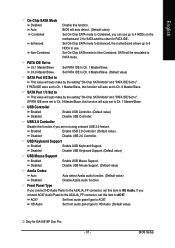
... the setting "On-Chip SATA Mode" and "PATA IDE Set to PATA mode. SATA Port 1/3 Set to This value will be simulated to ". BIOS Setup If you connect AC97 Audio Panel to the AZALIA_FP connector, set this item to Ch. 1 Master/Slave. USB 2.0 Controller Disable this function....to use up to 6 HDDs to 4 HDDs on the Enhanced motherboard; 2 for SATA and the other for GA-8I915P Duo Pro. - 37 - USB Keyboard Support Enabled Enable USB Keyboard Support. Auto Combined BIOS will auto make by the setting "On-Chip SATA Mode" and "PATA IDE Set to HD Audio. USB Controller...
... the setting "On-Chip SATA Mode" and "PATA IDE Set to PATA mode. SATA Port 1/3 Set to This value will be simulated to ". BIOS Setup If you connect AC97 Audio Panel to the AZALIA_FP connector, set this item to Ch. 1 Master/Slave. USB 2.0 Controller Disable this function....to use up to 6 HDDs to 4 HDDs on the Enhanced motherboard; 2 for SATA and the other for GA-8I915P Duo Pro. - 37 - USB Keyboard Support Enabled Enable USB Keyboard Support. Auto Combined BIOS will auto make by the setting "On-Chip SATA Mode" and "PATA IDE Set to HD Audio. USB Controller...

Manual
Page 38
... Select This item allows you to ASKIR Mode. GA-8I915P Duo (Pro) Motherboard - 38 - Onboard H/W 1394 Enabled Disabled Enable onboard IEEE 1394 function.(Default value) Disable this function. (Default value) Onboard Serial Port 1 Auto 3F8/IRQ4 BIOS will automatically setup the port 1 address. Disabled ... ROM of the onboard LAN2 chip. Onboard LAN1 Boot ROM This function decide whether to IrDA Mode. (Default value) Only for GA-8I915P Duo Pro. Enable onboard Serial port 1 and address is 2E8. Disabled Disable onboard Serial port 1. Enabled Enable this function. IrDA Set onboard...
... Select This item allows you to ASKIR Mode. GA-8I915P Duo (Pro) Motherboard - 38 - Onboard H/W 1394 Enabled Disabled Enable onboard IEEE 1394 function.(Default value) Disable this function. (Default value) Onboard Serial Port 1 Auto 3F8/IRQ4 BIOS will automatically setup the port 1 address. Disabled ... ROM of the onboard LAN2 chip. Onboard LAN1 Boot ROM This function decide whether to IrDA Mode. (Default value) Only for GA-8I915P Duo Pro. Enable onboard Serial port 1 and address is 2E8. Disabled Disable onboard Serial port 1. Enabled Enable this function. IrDA Set onboard...
Manual
Page 43
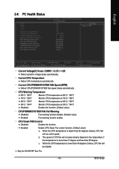
c. BIOS Setup When the CPU temperature is lower than 40 degrees Celsius, CPU fan will run at 90oC / 194oF. CPU Smart FAN Control Disabled Disable this ...) Enabled Fan warning function enable. When the CPU temperature is higher than 65 degree. b. Enabled Enable CPU Smart Fan control function. (Default value) a. Only for GA-8I915P Duo Pro. - 43 - The speed of CPU fan will increase linearly depand on the temperature if the temperature is more than 41 degree and less than 65...
c. BIOS Setup When the CPU temperature is lower than 40 degrees Celsius, CPU fan will run at 90oC / 194oF. CPU Smart FAN Control Disabled Disable this ...) Enabled Fan warning function enable. When the CPU temperature is higher than 65 degree. b. Enabled Enable CPU Smart Fan control function. (Default value) a. Only for GA-8I915P Duo Pro. - 43 - The speed of CPU fan will increase linearly depand on the temperature if the temperature is more than 41 degree and less than 65...
Manual
Page 44
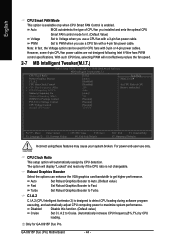
...power cables are not designed following Intel 4-Wire fans PWM control specifications. Robust Graphics Booster Select the options can be used for GA-8I915P Duo Pro. GA-8I915P Duo (Pro) Motherboard - 44 - With such CPU fans, selecting PWM will automatically assign by CPU loading. For power end-user use ...a CPU fan with 3-pin or 4-pin power cables. C.I.A.2 C.I.A.2 (CPU Intelligent Acelerator 2) is not changeable. Auto BIOS autodetects the type of CPU fan you installed and sets the optimal CPU Smart FAN control mode for it. (Default Value) Voltage...
...power cables are not designed following Intel 4-Wire fans PWM control specifications. Robust Graphics Booster Select the options can be used for GA-8I915P Duo Pro. GA-8I915P Duo (Pro) Motherboard - 44 - With such CPU fans, selecting PWM will automatically assign by CPU loading. For power end-user use ...a CPU fan with 3-pin or 4-pin power cables. C.I.A.2 C.I.A.2 (CPU Intelligent Acelerator 2) is not changeable. Auto BIOS autodetects the type of CPU fan you installed and sets the optimal CPU Smart FAN control mode for it. (Default Value) Voltage...
Manual
Page 46
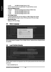
...-User use only! Set PCI-E OverVoltage Control to +0.1V. Only for GA-8I915P Duo Pro. There are English, German, Traditional Chinese, Simplified Chinese and Japanese. 2-9 Load Fail-Safe Defaults CMOS Setup Utility-Copyright (C) 1984-2004 Award Software ` Standard CMOS Features Select Language 1 ` Advanced BIOS Features Load Fail-Safe Defaults ` Integrated Peripherals Load Optimized Defaults ` Power...
...-User use only! Set PCI-E OverVoltage Control to +0.1V. Only for GA-8I915P Duo Pro. There are English, German, Traditional Chinese, Simplified Chinese and Japanese. 2-9 Load Fail-Safe Defaults CMOS Setup Utility-Copyright (C) 1984-2004 Award Software ` Standard CMOS Features Select Language 1 ` Advanced BIOS Features Load Fail-Safe Defaults ` Integrated Peripherals Load Optimized Defaults ` Power...


