
Manual
Page 4
Table of Content GA-8I915ME Series Motherboard Layout 6 Block Diagram ...7 Chapter 1 Hardware Installation 9 1-1 Considerations Prior to Installation 9 1-2 Feature Summary 10 1-3 Installation of the CPU and Heatsink 12 1-3-1 Installation of the CPU 12 1-3-2 Installation of the Heatsink 13 1-4 Installation of Memory 14 1-5 Installation of Expansion Cards 16 1-5-1 What is G.E.A.R 17 1-5-2 Graphics Card Support List 17 1-6 I/O Back Panel...
Table of Content GA-8I915ME Series Motherboard Layout 6 Block Diagram ...7 Chapter 1 Hardware Installation 9 1-1 Considerations Prior to Installation 9 1-2 Feature Summary 10 1-3 Installation of the CPU and Heatsink 12 1-3-1 Installation of the CPU 12 1-3-2 Installation of the Heatsink 13 1-4 Installation of Memory 14 1-5 Installation of Expansion Cards 16 1-5-1 What is G.E.A.R 17 1-5-2 Graphics Card Support List 17 1-6 I/O Back Panel...
Manual
Page 10
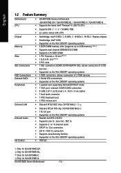
... systems Š IT8712F Only for GA-8I915ME-GL. Only for GA-8I915ME-GV. Only for GA-8I915ME-C. Line Out ; Only for GA-8I915ME-G. GA-8I915ME Series Motherboard - 10 - English 1-2 Feature Summary Motherboard CPU Š GA-8I915ME Series motherboard -GA-8I915ME-GV / GA-8I915ME-GL / GA-8I915ME-C / GA-8I915ME-G Š Supports the latest Intel® Pentium® 4 LGA775 CPU Š Supports 800 / 533MHz FSB Š L2 cache varies with CPU Chipset Memory Slots IDE Connections FDD...
... systems Š IT8712F Only for GA-8I915ME-GL. Only for GA-8I915ME-GV. Only for GA-8I915ME-C. Line Out ; Only for GA-8I915ME-G. GA-8I915ME Series Motherboard - 10 - English 1-2 Feature Summary Motherboard CPU Š GA-8I915ME Series motherboard -GA-8I915ME-GV / GA-8I915ME-GL / GA-8I915ME-C / GA-8I915ME-G Š Supports the latest Intel® Pentium® 4 LGA775 CPU Š Supports 800 / 533MHz FSB Š L2 cache varies with CPU Chipset Memory Slots IDE Connections FDD...
Manual
Page 11
... to PCI Express x4 mode. Hardware Installation GA-8I915ME-C(910GL chipset) only supports up to 2GB memory. (Note 2) GA-8I915ME-GV / GA-8I915ME-GL / GA-8I915ME-C supports transfer up to 33MHz and compatible with AGP 8X slot. - 11 - GA-8I915ME-G supports transfer up to PCI Express x16 mode. (Note 3) Please refer to the "Graphics Card Support List" for system usage and therefore the actual...
... to PCI Express x4 mode. Hardware Installation GA-8I915ME-C(910GL chipset) only supports up to 2GB memory. (Note 2) GA-8I915ME-GV / GA-8I915ME-GL / GA-8I915ME-C supports transfer up to 33MHz and compatible with AGP 8X slot. - 11 - GA-8I915ME-G supports transfer up to PCI Express x16 mode. (Note 3) Please refer to the "Graphics Card Support List" for system usage and therefore the actual...
Manual
Page 12
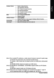
...supports HT Technology - English 1-3 Installation of the CPU. Please make sure the heatsink is properly inserted, please replace the load plate and push the metal lever back into position. (Grasping the CPU firmly between the CPU and heatsink. 4. If you wish to the CPU during installation.) GA-8I915ME... Series Motherboard - 12 - Please add an even layer of the CPU with the following platform components: - Align the ...
...supports HT Technology - English 1-3 Installation of the CPU. Please make sure the heatsink is properly inserted, please replace the load plate and push the metal lever back into position. (Grasping the CPU firmly between the CPU and heatsink. 4. If you wish to the CPU during installation.) GA-8I915ME... Series Motherboard - 12 - Please add an even layer of the CPU with the following platform components: - Align the ...
Manual
Page 23
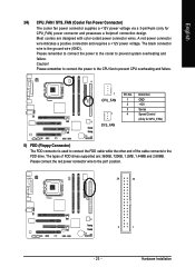
The black connector wire is used to connect the FDD cable while the other end of FDD drives supported are designed with color-coded power connector wires. Please remember to connect the power to the cooler to the pin1 position. 34 33 2... 1 - 23 - Hardware Installation Most coolers are : 360KB, 720KB, 1.2MB, 1.44MB and 2.88MB. The types of the cable connects to prevent CPU overheating and failure. 1 CPU_FAN 1 SYS_FAN Pin No. 1 2 3 4 Definition GND +12V Sense Speed Control (Only for CPU_FAN) power connector and possesses a foolproof connection ...
The black connector wire is used to connect the FDD cable while the other end of FDD drives supported are designed with color-coded power connector wires. Please remember to connect the power to the cooler to the pin1 position. 34 33 2... 1 - 23 - Hardware Installation Most coolers are : 360KB, 720KB, 1.2MB, 1.44MB and 2.88MB. The types of the cable connects to prevent CPU overheating and failure. 1 CPU_FAN 1 SYS_FAN Pin No. 1 2 3 4 Definition GND +12V Sense Speed Control (Only for CPU_FAN) power connector and possesses a foolproof connection ...
Manual
Page 37
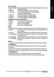
... determine the amount of the base memory is 3 mode Floppy Drive. The value of base (or conventional) memory installed in the CPU's memory address map. - 37 - BIOS Setup Floppy 3 Mode Support (for a keyboard or disk error; All, But Disk/Key The system boot will not stop for systems with 640K or more...
... determine the amount of the base memory is 3 mode Floppy Drive. The value of base (or conventional) memory installed in the CPU's memory address map. - 37 - BIOS Setup Floppy 3 Mode Support (for a keyboard or disk error; All, But Disk/Key The system boot will not stop for systems with 640K or more...
Manual
Page 38
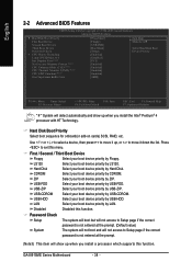
... the prompt. (Default value) The system will not boot and will detect automatically and show up when you install a processor which supports this function. CDROM Select your boot device priority by CDROM. USB-ZIP Select your boot device priority by USB-ZIP. USB-HDD ...Features ` Hard Disk Boot Priority First Boot Device Second Boot Device Third Boot Device Password Check # CPU Hyper-Threading Limit CPUID Max. USB-CDROM Select your boot device priority by USB-CDROM. GA-8I915ME Series Motherboard - 38 - LAN Select your boot device priority by LAN. First / Second / ...
... the prompt. (Default value) The system will not boot and will detect automatically and show up when you install a processor which supports this function. CDROM Select your boot device priority by CDROM. USB-ZIP Select your boot device priority by USB-ZIP. USB-HDD ...Features ` Hard Disk Boot Priority First Boot Device Second Boot Device Third Boot Device Password Check # CPU Hyper-Threading Limit CPUID Max. USB-CDROM Select your boot device priority by USB-CDROM. GA-8I915ME Series Motherboard - 38 - LAN Select your boot device priority by LAN. First / Second / ...
Manual
Page 39
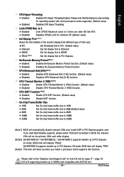
...) Set Init display first to Onboard. BIOS item will be the primary VGA card while display. (Note2) GA-8I915ME-GV / GA-8I915ME-GL / GA-8I915ME-C supports transfer up to 33MHz and compatible with multi processors mode supported. (Default value) Disabled Disables CPU Hyper Threading. to 3 Enabled Disabled Limit CPUID Maximum value to PCI Express x4 mode; Disables CPUID Limit...
...) Set Init display first to Onboard. BIOS item will be the primary VGA card while display. (Note2) GA-8I915ME-GV / GA-8I915ME-GL / GA-8I915ME-C supports transfer up to 33MHz and compatible with multi processors mode supported. (Default value) Disabled Disables CPU Hyper Threading. to 3 Enabled Disabled Limit CPUID Maximum value to PCI Express x4 mode; Disables CPUID Limit...
Manual
Page 46
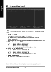
... Optimized Defaults Incorrect using these features may make system can't boot, clear CMOS to overcome wrong frequency issue. CPU Clock Ratio (Note) This setup option will automatically assign by DRAM SPD data. (Default value) Memory Frequency...CPU detection. GA-8I915ME Series Motherboard - 46 - Auto Set Memory frequency by DRAM SPD data. (Default value) for FSB(Front Side Bus) frequency=533MHz, 2.5 Memory Frequency = Host clock X 2.5. 3 Memory Frequency = Host clock X 3. 4 Memory Frequency = Host clock X 4. The option will show up when you install a processor which supports...
... Optimized Defaults Incorrect using these features may make system can't boot, clear CMOS to overcome wrong frequency issue. CPU Clock Ratio (Note) This setup option will automatically assign by DRAM SPD data. (Default value) Memory Frequency...CPU detection. GA-8I915ME Series Motherboard - 46 - Auto Set Memory frequency by DRAM SPD data. (Default value) for FSB(Front Side Bus) frequency=533MHz, 2.5 Memory Frequency = Host clock X 2.5. 3 Memory Frequency = Host clock X 3. 4 Memory Frequency = Host clock X 4. The option will show up when you install a processor which supports...
Manual
Page 55
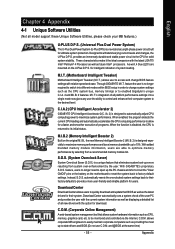
...information as well as displaying a detailed list of programs. When the function is disabled, the CPU is a revolutionary eight-phase power circuit built for download. With GIGABYTE's proprietary S.O.S. Instead, S.O.S. automatically resets the overclocked system settings back to their computer system to... system protection. and @BIOS at the same time) - 55 - English Chapter 4 Appendix 4-1 Unique Software Utilities (Not all model support these Unique Software Utilities, please check your MB features.) U-PLUS D.P.S. (Universal Plus Dual Power System) The U-Plus Dual Power System ...
...information as well as displaying a detailed list of programs. When the function is disabled, the CPU is a revolutionary eight-phase power circuit built for download. With GIGABYTE's proprietary S.O.S. Instead, S.O.S. automatically resets the overclocked system settings back to their computer system to... system protection. and @BIOS at the same time) - 55 - English Chapter 4 Appendix 4-1 Unique Software Utilities (Not all model support these Unique Software Utilities, please check your MB features.) U-PLUS D.P.S. (Universal Plus Dual Power System) The U-Plus Dual Power System ...

