
Manual
Page 4
...GA-8I915G-MFD Motherboard Layout 6 Block Diagram ...7 Chapter 1 Hardware Installation 9 1-1 Considerations Prior to Installation 9 1-2 Feature Summary 10 1-3 Installation of the CPU and Heatsink 12 1-3-1 Installation of the CPU 12 1-3-2 Installation of the Heatsink 13 1-4 Installation of Memory 14 1-5 Installation of Expansion Cards 16 1-6 I/O Back Panel Introduction 17 1-7 Connectors Introduction 18 Chapter 2 BIOS... Setup 29 The Main Menu (For example: BIOS Ver. : F5 30 2-1 Standard CMOS Features 32 2-2 Advanced BIOS Features 34 2-3 ...
...GA-8I915G-MFD Motherboard Layout 6 Block Diagram ...7 Chapter 1 Hardware Installation 9 1-1 Considerations Prior to Installation 9 1-2 Feature Summary 10 1-3 Installation of the CPU and Heatsink 12 1-3-1 Installation of the CPU 12 1-3-2 Installation of the Heatsink 13 1-4 Installation of Memory 14 1-5 Installation of Expansion Cards 16 1-6 I/O Back Panel Introduction 17 1-7 Connectors Introduction 18 Chapter 2 BIOS... Setup 29 The Main Menu (For example: BIOS Ver. : F5 30 2-1 Standard CMOS Features 32 2-2 Advanced BIOS Features 34 2-3 ...
Manual
Page 5
Channel Audio Function Introduction 67 4-2 Troubleshooting 71 - 5 - Chapter 3 Install Drivers 49 3-1 Install Chipset Drivers 49 3-2 SoftwareApplications 50 3-3 Driver CD Information 50 3-4 Hardware Information 51 3-5 Contact Us ...51 Chapter 4 Appendix 53 4-1 Unique Software Utilities 53 4-1-1 EasyTune 5 Introduction 54 4-1-2 Xpress Recovery Introduction 55 4-1-3 Flash BIOS Method Introduction 58 4-1-4 2- / 4- / 6- / 8-
Channel Audio Function Introduction 67 4-2 Troubleshooting 71 - 5 - Chapter 3 Install Drivers 49 3-1 Install Chipset Drivers 49 3-2 SoftwareApplications 50 3-3 Driver CD Information 50 3-4 Hardware Information 51 3-5 Contact Us ...51 Chapter 4 Appendix 53 4-1 Unique Software Utilities 53 4-1-1 EasyTune 5 Introduction 54 4-1-2 Xpress Recovery Introduction 55 4-1-3 Flash BIOS Method Introduction 58 4-1-4 2- / 4- / 6- / 8-

Manual
Page 6
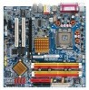
GA-8I915G-MFD Motherboard Layout KB_MS SPDIF_O SPDIF_I SYS_FAN CPU_FAN IT8712 IR ATX LPT LAN VGA R_USB ATX_12V LGA775 GA-8I915G-MFD DDRII1 DDRII2 DDRII3 DDRII4 IDE USB AUDIO1 AUDIO2 RTL8110S CODEC AZALIA_FP Intel 915G PCIE_1 COMA COMB PCIE_16 PCI1 FDD S_ATA3 BAT PCI2 ICH6 TSB43AB23 CLR_CMOS S_ATA0 S_ATA2 F2_1394 F1_1394 F_USB1 F_USB2 BIOS F_PANEL CD_IN S_ATA1 PWR_LED - 6 -
GA-8I915G-MFD Motherboard Layout KB_MS SPDIF_O SPDIF_I SYS_FAN CPU_FAN IT8712 IR ATX LPT LAN VGA R_USB ATX_12V LGA775 GA-8I915G-MFD DDRII1 DDRII2 DDRII3 DDRII4 IDE USB AUDIO1 AUDIO2 RTL8110S CODEC AZALIA_FP Intel 915G PCIE_1 COMA COMB PCIE_16 PCI1 FDD S_ATA3 BAT PCI2 ICH6 TSB43AB23 CLR_CMOS S_ATA0 S_ATA2 F2_1394 F1_1394 F_USB1 F_USB2 BIOS F_PANEL CD_IN S_ATA1 PWR_LED - 6 -

Manual
Page 7
... RTL 8110S TSB43AB23 Host Interface Intel 915G GMCH Intel ICH6 DDRII 533/400MHz DIMM Dual Channel Memory GMCHCLK (133/200MHz) 66MHz 33MHz 14.318MHz 48MHz BIOS 4 Serial ATA ATA33/66/100 IDE Channels Floppy IT 8712 LPT Port RJ45 CODEC COM Ports 8 USB Ports 24MHz 33MHz 2 PCI PS/2 KB/Mouse PCICLK...
... RTL 8110S TSB43AB23 Host Interface Intel 915G GMCH Intel ICH6 DDRII 533/400MHz DIMM Dual Channel Memory GMCHCLK (133/200MHz) 66MHz 33MHz 14.318MHz 48MHz BIOS 4 Serial ATA ATA33/66/100 IDE Channels Floppy IT 8712 LPT Port RJ45 CODEC COM Ports 8 USB Ports 24MHz 33MHz 2 PCI PS/2 KB/Mouse PCICLK...

Manual
Page 11
English Hardware Monitor BIOS Additional Features Overclocking Form Factor Š System voltage detection Š CPU temperature detection Š CPU / System fan speed detection Š CPU warning temperature Š CPU / System fan failure warning Š CPU smart fan control Š Use of licensed AWARD BIOS Š Supports Q-Flash Š Supports @BIOS Š Supports EasyTune 5 (only supports Hardware Monitor function) Š Over Clock via BIOS (DDR II) Š Micro ATX form factor; 24.4cm x 24.4cm - 11 - Hardware Installation
English Hardware Monitor BIOS Additional Features Overclocking Form Factor Š System voltage detection Š CPU temperature detection Š CPU / System fan speed detection Š CPU warning temperature Š CPU / System fan failure warning Š CPU smart fan control Š Use of licensed AWARD BIOS Š Supports Q-Flash Š Supports @BIOS Š Supports EasyTune 5 (only supports Hardware Monitor function) Š Over Clock via BIOS (DDR II) Š Micro ATX form factor; 24.4cm x 24.4cm - 11 - Hardware Installation

Manual
Page 12
... the proper specifications, please do so according to the CPU during installation.) GA-8I915G-MFD Motherboard - 12 - Please make sure that supports HT Technology - Please set the CPU host frequency in the wrong direction, the CPU will not insert properly. BIOS: A BIOS that the system bus frequency be set the frequency beyond hardware specifications since...
... the proper specifications, please do so according to the CPU during installation.) GA-8I915G-MFD Motherboard - 12 - Please make sure that supports HT Technology - Please set the CPU host frequency in the wrong direction, the CPU will not insert properly. BIOS: A BIOS that the system bus frequency be set the frequency beyond hardware specifications since...

Manual
Page 14
... push it down. The motherboard supports DDR II memory modules, whereby BIOS will automatically detect memory capacity and specifications. Reverse the installation steps when you are designed so that memory of similar capacity, specifications and brand be installed in one direction. GA-8I915G-MFD Motherboard - 14 - Before installing or removing memory modules, please make...
... push it down. The motherboard supports DDR II memory modules, whereby BIOS will automatically detect memory capacity and specifications. Reverse the installation steps when you are designed so that memory of similar capacity, specifications and brand be installed in one direction. GA-8I915G-MFD Motherboard - 14 - Before installing or removing memory modules, please make...

Manual
Page 16
... steps outlined below: 1. Press the expansion card firmly into the computer. 2. GA-8I915G-MFD Motherboard - 16 - Replace the screw to install/Uninstall the VGA card. Remove your computer's chassis cover, screws and slot bracket from BIOS. 8. Please align the VGA card to the onboard PCI Express x 16 slot... and press firmly down on the computer, if necessary, setup BIOS utility of expansion card from the computer. 3. Replace your computer's chassis cover. 7. Install related driver from the operating system. English...
... steps outlined below: 1. Press the expansion card firmly into the computer. 2. GA-8I915G-MFD Motherboard - 16 - Replace the screw to install/Uninstall the VGA card. Remove your computer's chassis cover, screws and slot bracket from BIOS. 8. Please align the VGA card to the onboard PCI Express x 16 slot... and press firmly down on the computer, if necessary, setup BIOS utility of expansion card from the computer. 3. Replace your computer's chassis cover. 7. Install related driver from the operating system. English...

Manual
Page 21
... order to the computer via an IDE connector. Definition 1 GND 1 7 2 TXP 3 TXN 4 GND 5 RXN 6 RXP 7 GND - 21 - Hardware Installation Pin No. Please refer to the BIOS setting for information on settings, please refer to the instructions located on the IDE device). 40 39 2 1 7) S_ATA0/S_ATA1/S_ATA2/S_ATA3 (Serial ATA Connector) Serial...
... order to the computer via an IDE connector. Definition 1 GND 1 7 2 TXP 3 TXN 4 GND 5 RXN 6 RXP 7 GND - 21 - Hardware Installation Pin No. Please refer to the BIOS setting for information on settings, please refer to the instructions located on the IDE device). 40 39 2 1 7) S_ATA0/S_ATA1/S_ATA2/S_ATA3 (Serial ATA Connector) Serial...

Manual
Page 23
... the audio panel cable, incorrect connection between the cable and connector will blink when the system enters suspend mode. To enable AC'97 Audio, from BIOS settings, set Front Panel Type under Integrated Peripherals to indicate whether the system is on/off. It will make the device unable to connect HD...
... the audio panel cable, incorrect connection between the cable and connector will blink when the system enters suspend mode. To enable AC'97 Audio, from BIOS settings, set Front Panel Type under Integrated Peripherals to indicate whether the system is on/off. It will make the device unable to connect HD...

Manual
Page 29
... the Internet. To exit the Help Window press . - 29 - You can be reset to a new BIOS, either Gigabyte's Q-Flash or @BIOS utility can enter the BIOS setup screen by pressing "Ctrl + F1". Quit and not save the current BIOS to a disk in the CMOS SRAM of the highlighted setup function is turned on the motherboard...
... the Internet. To exit the Help Window press . - 29 - You can be reset to a new BIOS, either Gigabyte's Q-Flash or @BIOS utility can enter the BIOS setup screen by pressing "Ctrl + F1". Quit and not save the current BIOS to a disk in the CMOS SRAM of the highlighted setup function is turned on the motherboard...

Manual
Page 30
... Main Menu (For example: BIOS Ver. : F5) Once you want, please press "Ctrl+F1" to search the advanced option hidden. Please Load Optimized Defaults in best performance configuration. This action makes the system reset to accept or enter the sub-menu. GA-8I915G-MFD Motherboard - 30 - If ...you can't find the setting you enter Award BIOS CMOS Setup Utility, the Main Menu (as usual. CMOS Setup Utility-Copyright (C) 1984-2004 Award Software...
... Main Menu (For example: BIOS Ver. : F5) Once you want, please press "Ctrl+F1" to search the advanced option hidden. Please Load Optimized Defaults in best performance configuration. This action makes the system reset to accept or enter the sub-menu. GA-8I915G-MFD Motherboard - 30 - If ...you can't find the setting you enter Award BIOS CMOS Setup Utility, the Main Menu (as usual. CMOS Setup Utility-Copyright (C) 1984-2004 Award Software...

Manual
Page 31
It allows you to limit access to the system. „ Save & Exit Setup Save CMOS value settings to Setup. „ Set User Password Change, set , or disable password. It allows you to limit access to the system and Setup, or just to CMOS and exit setup. „ Exit Without Saving Abandon all CMOS value changes and exit setup. - 31 - BIOS Setup English „ Set Supervisor Password Change, set , or disable password.
It allows you to limit access to the system. „ Save & Exit Setup Save CMOS value settings to Setup. „ Set User Password Change, set , or disable password. It allows you to limit access to the system and Setup, or just to CMOS and exit setup. „ Exit Without Saving Abandon all CMOS value changes and exit setup. - 31 - BIOS Setup English „ Set Supervisor Password Change, set , or disable password.

Manual
Page 32
... detection. Day The day, from 1 to 31 (or the maximum allowed in the month) Year The year, from Sun to Sat, determined by the BIOS and is , , , . Enter the appropriate option based on this if no IDE devices are : CHS/LBA/Large/Auto(default:Auto) Hard drive information... three methods: Auto Allows BIOS to set the access mode for faster system start up. Through Dec. to Dec. 1 to 2098 ESC: Exit F1: General Help F7: Optimized Defaults Date The date format is display only Month The month, Jan. The time is 13:00:00. GA-8I915G-MFD Motherboard - 32 - English...
... detection. Day The day, from 1 to 31 (or the maximum allowed in the month) Year The year, from Sun to Sat, determined by the BIOS and is , , , . Enter the appropriate option based on this if no IDE devices are : CHS/LBA/Large/Auto(default:Auto) Hard drive information... three methods: Auto Allows BIOS to set the access mode for faster system start up. Through Dec. to Dec. 1 to 2098 ESC: Exit F1: General Help F7: Optimized Defaults Date The date format is display only Month The month, Jan. The time is 13:00:00. GA-8I915G-MFD Motherboard - 32 - English...

Manual
Page 33
...will stop for Japan Area) Disabled Normal Floppy Drive. (Default value) Drive A Drive B Both Drive A is present during power up. BIOS Setup Halt on the motherboard, or 640K for a disk error; it will stop for systems with 640K or more memory installed on the ...byte capacity. 1.2M, 5.25" 5.25 inch AT-type high-density drive; 1.2M byte capacity (3.5 inch when 3 Mode is 3 mode Floppy Drive. Whenever the BIOS detects a non-fatal error the system will not stop for a keyboard error; Drive B is Enabled). 720K, 3.5" 1.44M, 3.5" 3.5 inch double-sided drive; 720K...
...will stop for Japan Area) Disabled Normal Floppy Drive. (Default value) Drive A Drive B Both Drive A is present during power up. BIOS Setup Halt on the motherboard, or 640K for a disk error; it will stop for systems with 640K or more memory installed on the ...byte capacity. 1.2M, 5.25" 5.25 inch AT-type high-density drive; 1.2M byte capacity (3.5 inch when 3 Mode is 3 mode Floppy Drive. Whenever the BIOS detects a non-fatal error the system will not stop for a keyboard error; Drive B is Enabled). 720K, 3.5" 1.44M, 3.5" 3.5 inch double-sided drive; 720K...

Manual
Page 34
...boot device priority by ZIP. USB-HDD Select your boot device priority by USB-HDD. English 2-2 Advanced BIOS Features CMOS Setup Utility-Copyright (C) 1984-2004 Award Software Advanced BIOS Features ` Hard Disk Boot Priority First Boot Device Second Boot Device Third Boot Device Password Check # CPU...up , or to move it up when you install a processor which supports this menu. LAN Select your boot device priority by LAN. GA-8I915G-MFD Motherboard - 34 - Hard Disk Select your boot device priority by Hard Disk. LS120 Select your boot device priority by LS120.
...boot device priority by ZIP. USB-HDD Select your boot device priority by USB-HDD. English 2-2 Advanced BIOS Features CMOS Setup Utility-Copyright (C) 1984-2004 Award Software Advanced BIOS Features ` Hard Disk Boot Priority First Boot Device Second Boot Device Third Boot Device Password Check # CPU...up , or to move it up when you install a processor which supports this menu. LAN Select your boot device priority by LAN. GA-8I915G-MFD Motherboard - 34 - Hard Disk Select your boot device priority by Hard Disk. LS120 Select your boot device priority by LS120.

Manual
Page 35
... use older OS like NT4. (Default value) Disables CPUID Limit for operating system with multi processors mode supported. (Default value) Disabled Disables CPU Hyper Threading. BIOS Setup Disabled Disables No-Execute Memory Protect function. (Default value) CPU Enhanced Halt (C1E) (Note) Enabled Disabled Enables CPU Enhanced Halt (C1E) function. CPU Hyper...
... use older OS like NT4. (Default value) Disables CPUID Limit for operating system with multi processors mode supported. (Default value) Disabled Disables CPU Hyper Threading. BIOS Setup Disabled Disables No-Execute Memory Protect function. (Default value) CPU Enhanced Halt (C1E) (Note) Enabled Disabled Enables CPU Enhanced Halt (C1E) function. CPU Hyper...

Manual
Page 37
...USB Mouse Support. (Default value) Azalia Codec Auto Disabled Auto detect Azalia audio function. (Default value) Disable Azalia audio function. Auto Combined BIOS will be simulated to ". Enhanced Set On-Chip SATA mode to Enhanced, the motherboard allows up to Ch. 1 Master/Slave. PATA IDE.... AC97 Set front audio panel type to AC97. USB 2.0 Controller Disable this function. USB Keyboard Support Enabled Enable USB Keyboard Support. BIOS Setup Front Panel Type If you connect HD Audio Panel to the AZALIA_FP connector, set this function will auto set to HD Audio....
...USB Mouse Support. (Default value) Azalia Codec Auto Disabled Auto detect Azalia audio function. (Default value) Disable Azalia audio function. Auto Combined BIOS will be simulated to ". Enhanced Set On-Chip SATA mode to Enhanced, the motherboard allows up to Ch. 1 Master/Slave. PATA IDE.... AC97 Set front audio panel type to AC97. USB 2.0 Controller Disable this function. USB Keyboard Support Enabled Enable USB Keyboard Support. BIOS Setup Front Panel Type If you connect HD Audio Panel to the AZALIA_FP connector, set this function will auto set to HD Audio....

Manual
Page 38
... Enable Onboard H/W LAN function. (Default value) Disabled Disable this function. (Default value) Onboard Serial Port 1 Auto 3F8/IRQ4 BIOS will automatically setup the port 1 address. Onboard LAN Boot ROM This function decide whether to IrDA Mode. Onboard Serial Port 2 Auto 3F8/IRQ4... to determine which Infra Red(IR) function of the onboard LAN chip. UR2 Duplex Mode This feature allows you to seclect IR mode. GA-8I915G-MFD Motherboard - 38 - Half IR Function Duplex Half. (Default value) Full IR Function Duplex Full. Disabled Disable this function. Normal ASKIR...
... Enable Onboard H/W LAN function. (Default value) Disabled Disable this function. (Default value) Onboard Serial Port 1 Auto 3F8/IRQ4 BIOS will automatically setup the port 1 address. Onboard LAN Boot ROM This function decide whether to IrDA Mode. Onboard Serial Port 2 Auto 3F8/IRQ4... to determine which Infra Red(IR) function of the onboard LAN chip. UR2 Duplex Mode This feature allows you to seclect IR mode. GA-8I915G-MFD Motherboard - 38 - Half IR Function Duplex Half. (Default value) Full IR Function Duplex Full. Disabled Disable this function. Normal ASKIR...

Manual
Page 39
... Mode SPP Using Parallel port as Standard Parallel Port. (Default value) EPP Using Parallel port as ECP & EPP mode. to S3/STR(Suspend To RAM). BIOS Setup Press power button 4 sec. Enabled Enable Power on by Ring function. (Default value) - 39 - ECP+EPP Using Parallel port as Enhanced Parallel Port. Enter...
... Mode SPP Using Parallel port as Standard Parallel Port. (Default value) EPP Using Parallel port as ECP & EPP mode. to S3/STR(Suspend To RAM). BIOS Setup Press power button 4 sec. Enabled Enable Power on by Ring function. (Default value) - 39 - ECP+EPP Using Parallel port as Enhanced Parallel Port. Enter...


