Manual
Page 1
GA-8I915G-MF GA-8I915GM Intel® Pentium® 4 LGA775 Processor Motherboard User's Manual Rev. 2204 12ME-8I915GMF-2204 * The WEEE marking on the product indicates this product must not be disposed of with user's other household waste and must be handed over to a designated collection point for the recycling of waste electrical and electronic equipment!! * The WEEE marking applies only in European Union's member states.
GA-8I915G-MF GA-8I915GM Intel® Pentium® 4 LGA775 Processor Motherboard User's Manual Rev. 2204 12ME-8I915GMF-2204 * The WEEE marking on the product indicates this product must not be disposed of with user's other household waste and must be handed over to a designated collection point for the recycling of waste electrical and electronic equipment!! * The WEEE marking applies only in European Union's member states.
Manual
Page 2
Motherboard GA-8I915G-MF Jun. 11, 2004 Motherboard GA-8I915G-MF Jun. 11, 2004
Motherboard GA-8I915G-MF Jun. 11, 2004 Motherboard GA-8I915G-MF Jun. 11, 2004

Manual
Page 3
... information and specifications, please carefully read the "Product User Manual". „ For detailed information related to Gigabyte's unique features, please go to the "Technology Guide" section on Gigabyte's website to assist in any form or by any means without prior notice. For more product details, ...Product Manual Classification In order to read or download the information you need. Notice The written content provided with this product, Gigabyte has categorized the user manual in the manual are subject to their respective companies. Copyright (c) 2004 GIGA-BYTE TECHNOLOGY CO.,...
... information and specifications, please carefully read the "Product User Manual". „ For detailed information related to Gigabyte's unique features, please go to the "Technology Guide" section on Gigabyte's website to assist in any form or by any means without prior notice. For more product details, ...Product Manual Classification In order to read or download the information you need. Notice The written content provided with this product, Gigabyte has categorized the user manual in the manual are subject to their respective companies. Copyright (c) 2004 GIGA-BYTE TECHNOLOGY CO.,...
Manual
Page 4
Table of Content GA-8I915G-MF Motherboard Layout 6 Block Diagram ...7 Chapter 1 Hardware Installation 9 1-1 Considerations Prior to Installation 9 1-2 Feature Summary 10 1-3 Installation of the CPU and Heatsink 12 1-3-1 Installation of the ...
Table of Content GA-8I915G-MF Motherboard Layout 6 Block Diagram ...7 Chapter 1 Hardware Installation 9 1-1 Considerations Prior to Installation 9 1-2 Feature Summary 10 1-3 Installation of the CPU and Heatsink 12 1-3-1 Installation of the ...

Manual
Page 5
Chapter 3 Install Drivers 47 3-1 Install Chipset Drivers 47 3-2 SoftwareApplications 48 3-3 Driver CD Information 48 3-4 Hardware Information 49 3-5 Contact Us ...49 Chapter 4 Appendix 51 4-1 Unique Software Utilities 51 4-1-1 EasyTune 5 Introduction 52 4-1-2 Xpress Recovery2 Introduction 53 4-1-3 Flash BIOS Method Introduction 55 4-1-4 2- / 4- / 6- / 8- Channel Audio Function Introduction 64 4-2 Troubleshooting 68 - 5 -
Chapter 3 Install Drivers 47 3-1 Install Chipset Drivers 47 3-2 SoftwareApplications 48 3-3 Driver CD Information 48 3-4 Hardware Information 49 3-5 Contact Us ...49 Chapter 4 Appendix 51 4-1 Unique Software Utilities 51 4-1-1 EasyTune 5 Introduction 52 4-1-2 Xpress Recovery2 Introduction 53 4-1-3 Flash BIOS Method Introduction 55 4-1-4 2- / 4- / 6- / 8- Channel Audio Function Introduction 64 4-2 Troubleshooting 68 - 5 -
Manual
Page 6
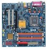
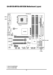
Only for GA-8I915G-MF. GA-8I915G-MF/GA-8I915GM Motherboard Layout IT8712 KB_MS SPDIF_O SPDIF_I CPU_FAN LGA775 SYS_FAN IR ATX VGA LPT R_USB ATX_12V USB LAN AZALIA_FP AUDIO1 AUDIO2 PCIE_16 RTL8110S RTL8100C CD_IN CODEC PCIE_1 COMA COMB GA-8I915G-MF DDR1 DDR2 Intel 915G IDE FDD DDR3 DDR4 PCI1 PCI2 ICH6 TSB43AB23 F2_1394 F1_1394 F_USB1 F_USB2 BAT S_ATA3 S_ATA2 S_ATA1 S_ATA0 CLR_CMOS BIOS PWR_LED F_PANEL Only for GA-8I915GM. - 6 -
Only for GA-8I915G-MF. GA-8I915G-MF/GA-8I915GM Motherboard Layout IT8712 KB_MS SPDIF_O SPDIF_I CPU_FAN LGA775 SYS_FAN IR ATX VGA LPT R_USB ATX_12V USB LAN AZALIA_FP AUDIO1 AUDIO2 PCIE_16 RTL8110S RTL8100C CD_IN CODEC PCIE_1 COMA COMB GA-8I915G-MF DDR1 DDR2 Intel 915G IDE FDD DDR3 DDR4 PCI1 PCI2 ICH6 TSB43AB23 F2_1394 F1_1394 F_USB1 F_USB2 BAT S_ATA3 S_ATA2 S_ATA1 S_ATA0 CLR_CMOS BIOS PWR_LED F_PANEL Only for GA-8I915GM. - 6 -
Manual
Page 7
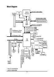
Only for GA-8I915G-MF. Block Diagram PCI-ECLK VGA (100MHz) PCI Express x16 1 PCIExpress x 1Ports PCI-ECLK(100MHz) PCI Express x1 Bus PCI Bsu TSB43AB23 RTL8110S RTL8100C RJ45 2 .../Mouse 3 IEEE1394 Center/Subwoofer Speaker Out Surround Speaker Out Side Speaker Out MIC Line-Out Line-In SPDIF In SPDIF Out PCICLK (33MHz) Only for GA-8I915GM. - 7 -
Only for GA-8I915G-MF. Block Diagram PCI-ECLK VGA (100MHz) PCI Express x16 1 PCIExpress x 1Ports PCI-ECLK(100MHz) PCI Express x1 Bus PCI Bsu TSB43AB23 RTL8110S RTL8100C RJ45 2 .../Mouse 3 IEEE1394 Center/Subwoofer Speaker Out Surround Speaker Out Side Speaker Out MIC Line-Out Line-In SPDIF In SPDIF Out PCICLK (33MHz) Only for GA-8I915GM. - 7 -

Manual
Page 9
... antistatic pad or within the computer casing. 6. Turning on top of the motherboard or any metal leads or connectors. 3. Damage due to be an unofficial Gigabyte product. - 9 - Please verify that all cables and power connectors are uncertain about any installation steps or have these items on the computer power during the...
... antistatic pad or within the computer casing. 6. Turning on top of the motherboard or any metal leads or connectors. 3. Damage due to be an unofficial Gigabyte product. - 9 - Please verify that all cables and power connectors are uncertain about any installation steps or have these items on the computer power during the...
Manual
Page 10
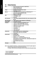
Only for GA-8I915G-MF. GA-8I915G-MF/GA-8I915GM Motherboard - 10 - Center/Subwoofer Speaker Out ;Side Speaker Out connection Š Supports SPDIF In/Out connection Š CD In Š IT8712 (Note 1) Due to ... chip (10/100 Mbit) Š 1 RJ 45 port Š ALC880 CODEC Š High Definition Audio Š Supports 2 / 4 / 6 / 8 channel audio Š Supports Line In ; Only for GA-8I915GM. Surround Speaker Out (Rear Speaker Out) ; For example, 4 GB of memory size will instead be shown as 3.xxGB memory during system startup. MIC ; Line...
Only for GA-8I915G-MF. GA-8I915G-MF/GA-8I915GM Motherboard - 10 - Center/Subwoofer Speaker Out ;Side Speaker Out connection Š Supports SPDIF In/Out connection Š CD In Š IT8712 (Note 1) Due to ... chip (10/100 Mbit) Š 1 RJ 45 port Š ALC880 CODEC Š High Definition Audio Š Supports 2 / 4 / 6 / 8 channel audio Š Supports Line In ; Only for GA-8I915GM. Surround Speaker Out (Rear Speaker Out) ; For example, 4 GB of memory size will instead be shown as 3.xxGB memory during system startup. MIC ; Line...
Manual
Page 11
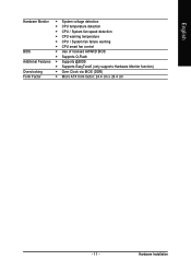
English Hardware Monitor Š System voltage detection Š CPU temperature detection Š CPU / System fan speed detection Š CPU warning temperature Š CPU / System fan failure warning Š CPU smart fan control BIOS Š Use of licensed AWARD BIOS Š Supports Q-Flash Additional Features Š Supports @BIOS Š Supports EasyTune5 (only supports Hardware Monitor function) Overclocking Š Over Clock via BIOS (DDR) Form Factor Š Micro ATX form factor; 24.4 cm x 24.4 cm - 11 - Hardware Installation
English Hardware Monitor Š System voltage detection Š CPU temperature detection Š CPU / System fan speed detection Š CPU warning temperature Š CPU / System fan failure warning Š CPU smart fan control BIOS Š Use of licensed AWARD BIOS Š Supports Q-Flash Additional Features Š Supports @BIOS Š Supports EasyTune5 (only supports Hardware Monitor function) Overclocking Š Over Clock via BIOS (DDR) Form Factor Š Micro ATX form factor; 24.4 cm x 24.4 cm - 11 - Hardware Installation
Manual
Page 12
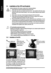
... for HT Technology 1-3-1 Installation of the CPU Metal Lever Fig. 1 Gently lift the metal lever located on the CPU prior to the CPU during installation.) GA-8I915G-MF/GA-8I915GM Motherboard - 12 - Align the indented corner of the CPU with the following platform components: - OS: An operation system that the motherboard supports the...
... for HT Technology 1-3-1 Installation of the CPU Metal Lever Fig. 1 Gently lift the metal lever located on the CPU prior to the CPU during installation.) GA-8I915G-MF/GA-8I915GM Motherboard - 12 - Align the indented corner of the CPU with the following platform components: - OS: An operation system that the motherboard supports the...

Manual
Page 13
Hardware Installation Fig. 6 Finally, please attach the power connector of the heatsink to install.)Please note the direction of arrow sign on the motherboard.Pressing down the push pins diagonally. The heatsink may adhere to the CPU as the picture, the installation is to the CPU fan header located on the surface of the installed CPU. Fig. 4 Please make sure the push pins aim to the pin hole on the male push pin doesn't face inwards before installation. (This instruction is suggested that either thermal tape rather than heat sink paste be used for detailed installation ...
Hardware Installation Fig. 6 Finally, please attach the power connector of the heatsink to install.)Please note the direction of arrow sign on the motherboard.Pressing down the push pins diagonally. The heatsink may adhere to the CPU as the picture, the installation is to the CPU fan header located on the surface of the installed CPU. Fig. 4 Please make sure the push pins aim to the pin hole on the male push pin doesn't face inwards before installation. (This instruction is suggested that either thermal tape rather than heat sink paste be used for detailed installation ...
Manual
Page 14
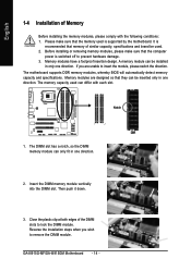
... be used is switched off to insert the module, please switch the direction. Then push it down. 3. Please make sure that the memory used . 2. GA-8I915G-MF/GA-8I915GM Motherboard - 14 - The motherboard supports DDR memory modules, whereby BIOS will automatically detect memory capacity and specifications. English 1-4 Installation of Memory Before installing the...
... be used is switched off to insert the module, please switch the direction. Then push it down. 3. Please make sure that the memory used . 2. GA-8I915G-MF/GA-8I915GM Motherboard - 14 - The motherboard supports DDR memory modules, whereby BIOS will automatically detect memory capacity and specifications. English 1-4 Installation of Memory Before installing the...

Manual
Page 15
...Only one DDR memory module is installed: The Dual Channel Technology can't operate when only one DDR memory module is installed. 2. English GA-8I915G-MF/GA-8I915GM supports the Dual Channel Technology. Three DDR memory modules are installed: Please note that The Dual Channel Technology will operate when two... modules are installed: If you want to the limitation of Memory Bus will operate only when those modules have the same memory size and type. GA-8I915G-MF/GA-8I915GM includes 4 DIMM sockets, and each Channel has two DIMM sockets as following: Channel A : DDR 1, DDR 2 Channel B : DDR 3, ...
...Only one DDR memory module is installed: The Dual Channel Technology can't operate when only one DDR memory module is installed. 2. English GA-8I915G-MF/GA-8I915GM supports the Dual Channel Technology. Three DDR memory modules are installed: Please note that The Dual Channel Technology will operate when two... modules are installed: If you want to the limitation of Memory Bus will operate only when those modules have the same memory size and type. GA-8I915G-MF/GA-8I915GM includes 4 DIMM sockets, and each Channel has two DIMM sockets as following: Channel A : DDR 1, DDR 2 Channel B : DDR 3, ...
Manual
Page 16
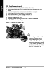
Replace your computer's chassis cover, screws and slot bracket from the computer. 3. Press the expansion card firmly into the computer. 2. GA-8I915G-MF/GA-8I915GM Motherboard - 16 - Read the related expansion card's instruction document before install the expansion card into expansion slot in the slot. 5. Replace the screw to ...
Replace your computer's chassis cover, screws and slot bracket from the computer. 3. Press the expansion card firmly into the computer. 2. GA-8I915G-MF/GA-8I915GM Motherboard - 16 - Read the related expansion card's instruction document before install the expansion card into expansion slot in the slot. 5. Replace the screw to ...
Manual
Page 17
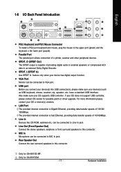
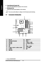
...Out) Connect the stereo speakers, earphone or front surround speakers to this connector. can be connected to Line In jack. Only for GA-8I915G-MF. Hardware Installation VGA Port Monitor can be connected to an external Dolby Digital Decoder. Line In Devices like CD-ROM, walkman .... Rear Speaker Out Connect the rear surround speakers to the upper port (green) and the keyboard o the lower port (purple). Only for GA-8I915GM. - 17 - SPDIF_O (SPDIF Out) The SPDIF output is capable of a printer, scanner and other peripheral devices. For more information please...
...Out) Connect the stereo speakers, earphone or front surround speakers to this connector. can be connected to Line In jack. Only for GA-8I915G-MF. Hardware Installation VGA Port Monitor can be connected to an external Dolby Digital Decoder. Line In Devices like CD-ROM, walkman .... Rear Speaker Out Connect the rear surround speakers to the upper port (green) and the keyboard o the lower port (purple). Only for GA-8I915GM. - 17 - SPDIF_O (SPDIF Out) The SPDIF output is capable of a printer, scanner and other peripheral devices. For more information please...
Manual
Page 18
GA-8I915G-MF/GA-8I915GM Motherboard - 18 - English Center/Subwoofer Speaker Out Connect the Center/Subwoofer speakers to this connector. You can use audio software to this connector. Side ...) F_USB1 / F_USB2 4) SYS_FAN 13) F1_1394 / F2_1394 5) FDD 14) IR 6) IDE 15) COMA / COMB 7) S_ATA0 / S_ATA1 / S_ATA2 / S_ATA3 16) CLR_CMOS 8) F_PANEL 17) BAT 9) PWR_LED Only for GA-8I915G-MF.
GA-8I915G-MF/GA-8I915GM Motherboard - 18 - English Center/Subwoofer Speaker Out Connect the Center/Subwoofer speakers to this connector. You can use audio software to this connector. Side ...) F_USB1 / F_USB2 4) SYS_FAN 13) F1_1394 / F2_1394 5) FDD 14) IR 6) IDE 15) COMA / COMB 7) S_ATA0 / S_ATA1 / S_ATA2 / S_ATA3 16) CLR_CMOS 8) F_PANEL 17) BAT 9) PWR_LED Only for GA-8I915G-MF.
Manual
Page 19
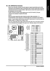
Caution! Please use a power supply that is unable to handle the system voltage requirements. If a power supply is used (300W or greater). Align the power connector with its proper location on the motherboard before plugging in the power cord ; Hardware Installation If you use a 24-pin ATX power supply, please remove the small cover on the power connector on the motherboard and connect tightly. Definition 13 1 1 3.3V 2 3.3V 3 GND 4 VCC 5 GND 6 VCC 7 GND 8 Power Good 9 5V SB(stand by +5V) 10 +12V 11 +12V 12 3.3V(Only for 24pins ATX) 24 12 13 ...
Caution! Please use a power supply that is unable to handle the system voltage requirements. If a power supply is used (300W or greater). Align the power connector with its proper location on the motherboard before plugging in the power cord ; Hardware Installation If you use a 24-pin ATX power supply, please remove the small cover on the power connector on the motherboard and connect tightly. Definition 13 1 1 3.3V 2 3.3V 3 GND 4 VCC 5 GND 6 VCC 7 GND 8 Power Good 9 5V SB(stand by +5V) 10 +12V 11 +12V 12 3.3V(Only for 24pins ATX) 24 12 13 ...
Manual
Page 20
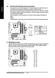
... failure. Most coolers are : 360KB, 720KB, 1.2MB, 1.44MB and 2.88MB. Please remember to connect the power to the cooler to the pin1 position. 34 33 2 1 GA-8I915G-MF/GA-8I915GM Motherboard - 20 - Please remember to connect the power to the CPU fan to prevent CPU overheating and failure. 1 CPU_FAN 1 SYS_FAN Pin No. 1 2 3 4 Definition...
... failure. Most coolers are : 360KB, 720KB, 1.2MB, 1.44MB and 2.88MB. Please remember to connect the power to the cooler to the pin1 position. 34 33 2 1 GA-8I915G-MF/GA-8I915GM Motherboard - 20 - Please remember to connect the power to the CPU fan to prevent CPU overheating and failure. 1 CPU_FAN 1 SYS_FAN Pin No. 1 2 3 4 Definition...
Manual
Page 21
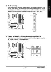
Hardware Installation Pin No. English 6) IDE (IDE Connector) An IDE device connects to work properly. One IDE connector can connect to one IDE device as Master and the other as Slave (for the Serial ATA and install the proper driver in order to the computer via an IDE connector. Please refer to the BIOS setting for information on settings, please refer to the instructions located on the IDE device). 40 39 2 1 7) S_ATA0/S_ATA1/S_ATA2/S_ATA3 (Serial ATA Connector, Controlled by ICH6) Serial ATA can then connect to connect two IDE devices, please set the jumper on one IDE ...
Hardware Installation Pin No. English 6) IDE (IDE Connector) An IDE device connects to work properly. One IDE connector can connect to one IDE device as Master and the other as Slave (for the Serial ATA and install the proper driver in order to the computer via an IDE connector. Please refer to the BIOS setting for information on settings, please refer to the instructions located on the IDE device). 40 39 2 1 7) S_ATA0/S_ATA1/S_ATA2/S_ATA3 (Serial ATA Connector, Controlled by ICH6) Serial ATA can then connect to connect two IDE devices, please set the jumper on one IDE ...