Manual
Page 1
GA-8I915G-MF GA-8I915GM Intel® Pentium® 4 LGA775 Processor Motherboard User's Manual Rev. 2204 12ME-8I915GMF-2204 * The WEEE marking on the product indicates this product must not be disposed of with user's other household waste and must be handed over to a designated collection point for the recycling of waste electrical and electronic equipment!! * The WEEE marking applies only in European Union's member states.
GA-8I915G-MF GA-8I915GM Intel® Pentium® 4 LGA775 Processor Motherboard User's Manual Rev. 2204 12ME-8I915GMF-2204 * The WEEE marking on the product indicates this product must not be disposed of with user's other household waste and must be handed over to a designated collection point for the recycling of waste electrical and electronic equipment!! * The WEEE marking applies only in European Union's member states.
Manual
Page 2
Motherboard GA-8I915G-MF Jun. 11, 2004 Motherboard GA-8I915G-MF Jun. 11, 2004
Motherboard GA-8I915G-MF Jun. 11, 2004 Motherboard GA-8I915G-MF Jun. 11, 2004
Manual
Page 4
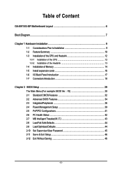
Table of Content GA-8I915G-MF Motherboard Layout 6 Block Diagram ...7 Chapter 1 Hardware Installation 9 1-1 Considerations Prior to Installation 9 1-2 Feature Summary 10 1-3 Installation of the CPU and Heatsink 12 1-3-1 Installation of the CPU ...
Table of Content GA-8I915G-MF Motherboard Layout 6 Block Diagram ...7 Chapter 1 Hardware Installation 9 1-1 Considerations Prior to Installation 9 1-2 Feature Summary 10 1-3 Installation of the CPU and Heatsink 12 1-3-1 Installation of the CPU ...
Manual
Page 6
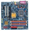
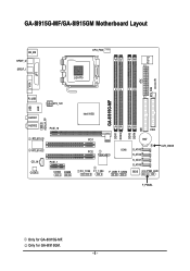
GA-8I915G-MF/GA-8I915GM Motherboard Layout IT8712 KB_MS SPDIF_O SPDIF_I CPU_FAN LGA775 SYS_FAN IR ATX VGA LPT R_USB ATX_12V USB LAN AZALIA_FP AUDIO1 AUDIO2 PCIE_16 RTL8110S RTL8100C CD_IN CODEC PCIE_1 COMA COMB GA-8I915G-MF DDR1 DDR2 Intel 915G IDE FDD DDR3 DDR4 PCI1 PCI2 ICH6 TSB43AB23 F2_1394 F1_1394 F_USB1 F_USB2 BAT S_ATA3 S_ATA2 S_ATA1 S_ATA0 CLR_CMOS BIOS PWR_LED F_PANEL Only for GA-8I915GM. - 6 - Only for GA-8I915G-MF.
GA-8I915G-MF/GA-8I915GM Motherboard Layout IT8712 KB_MS SPDIF_O SPDIF_I CPU_FAN LGA775 SYS_FAN IR ATX VGA LPT R_USB ATX_12V USB LAN AZALIA_FP AUDIO1 AUDIO2 PCIE_16 RTL8110S RTL8100C CD_IN CODEC PCIE_1 COMA COMB GA-8I915G-MF DDR1 DDR2 Intel 915G IDE FDD DDR3 DDR4 PCI1 PCI2 ICH6 TSB43AB23 F2_1394 F1_1394 F_USB1 F_USB2 BAT S_ATA3 S_ATA2 S_ATA1 S_ATA0 CLR_CMOS BIOS PWR_LED F_PANEL Only for GA-8I915GM. - 6 - Only for GA-8I915G-MF.
Manual
Page 7
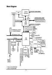
.../Mouse 3 IEEE1394 Center/Subwoofer Speaker Out Surround Speaker Out Side Speaker Out MIC Line-Out Line-In SPDIF In SPDIF Out PCICLK (33MHz) Only for GA-8I915GM. - 7 - Only for GA-8I915G-MF.
.../Mouse 3 IEEE1394 Center/Subwoofer Speaker Out Surround Speaker Out Side Speaker Out MIC Line-Out Line-In SPDIF In SPDIF Out PCICLK (33MHz) Only for GA-8I915GM. - 7 - Only for GA-8I915G-MF.
Manual
Page 10
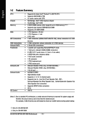
... (10/100 Mbit) Š 1 RJ 45 port Š ALC880 CODEC Š High Definition Audio Š Supports 2 / 4 / 6 / 8 channel audio Š Supports Line In ; GA-8I915G-MF/GA-8I915GM Motherboard - 10 - English 1-2 Feature Summary CPU Chipset Memory Slots IDE Connections FDD Connections Onboard SATA Peripherals Onboard LAN Onboard Audio I/O Control Š Supports the...a certain amount of memory is reserved for system usage and therefore the actual memory size is less than the stated amount. Only for GA-8I915G-MF. Only for GA-8I915GM. Surround Speaker Out (Rear Speaker Out) ;
... (10/100 Mbit) Š 1 RJ 45 port Š ALC880 CODEC Š High Definition Audio Š Supports 2 / 4 / 6 / 8 channel audio Š Supports Line In ; GA-8I915G-MF/GA-8I915GM Motherboard - 10 - English 1-2 Feature Summary CPU Chipset Memory Slots IDE Connections FDD Connections Onboard SATA Peripherals Onboard LAN Onboard Audio I/O Control Š Supports the...a certain amount of memory is reserved for system usage and therefore the actual memory size is less than the stated amount. Only for GA-8I915G-MF. Only for GA-8I915GM. Surround Speaker Out (Rear Speaker Out) ;
Manual
Page 12
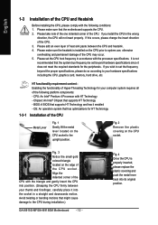
... overheating and permanent damage of the CPU Metal Lever Fig. 1 Gently lift the metal lever located on the CPU prior to the CPU during installation.) GA-8I915G-MF/GA-8I915GM Motherboard - 12 - English 1-3 Installation of the CPU and Heatsink Before installing the CPU, please comply with the processor specifications. Avoid twisting or bending motions...
... overheating and permanent damage of the CPU Metal Lever Fig. 1 Gently lift the metal lever located on the CPU prior to the CPU during installation.) GA-8I915G-MF/GA-8I915GM Motherboard - 12 - English 1-3 Installation of the CPU and Heatsink Before installing the CPU, please comply with the processor specifications. Avoid twisting or bending motions...
Manual
Page 14
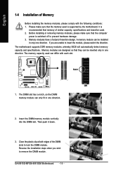
... DIMM module. Close the plastic clip at both edges of the DIMM slots to insert the module, please switch the direction. Then push it down. 3. GA-8I915G-MF/GA-8I915GM Motherboard - 14 - Before installing or removing memory modules, please make sure that memory of Memory Before installing the memory modules, please comply with each...
... DIMM module. Close the plastic clip at both edges of the DIMM slots to insert the module, please switch the direction. Then push it down. 3. GA-8I915G-MF/GA-8I915GM Motherboard - 14 - Before installing or removing memory modules, please make sure that memory of Memory Before installing the memory modules, please comply with each...

Manual
Page 15
English GA-8I915G-MF/GA-8I915GM supports the Dual Channel Technology. GA-8I915G-MF/GA-8I915GM includes 4 DIMM sockets, and each Channel has two DIMM sockets as following: Channel A : DDR 1, DDR 2 Channel B : DDR 3, DDR 4 If you want to work. If ...
English GA-8I915G-MF/GA-8I915GM supports the Dual Channel Technology. GA-8I915G-MF/GA-8I915GM includes 4 DIMM sockets, and each Channel has two DIMM sockets as following: Channel A : DDR 1, DDR 2 Channel B : DDR 3, DDR 4 If you want to work. If ...
Manual
Page 16
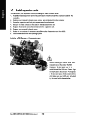
.../Uninstall the VGA card. Installing a PCI Express x 16 expansion card: Please carefully pull out the small whitedrawable bar at the end of the expansion card. 6. GA-8I915G-MF/GA-8I915GM Motherboard - 16 - Remove your expansion card by the small white-drawable bar. Read the related expansion card's instruction document before install the expansion card...
.../Uninstall the VGA card. Installing a PCI Express x 16 expansion card: Please carefully pull out the small whitedrawable bar at the end of the expansion card. 6. GA-8I915G-MF/GA-8I915GM Motherboard - 16 - Remove your expansion card by the small white-drawable bar. Read the related expansion card's instruction document before install the expansion card...
Manual
Page 17
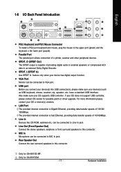
... connected to VGA port. Rear Speaker Out Connect the rear surround speakers to an external Dolby Digital Decoder. have a standard USB interface. Only for GA-8I915G-MF. Only for GA-8I915GM. - 17 - USB port Before you connect your device(s) into USB connector(s), please make sure your OS supports USB controller. Hardware Installation English 1-6 I/O Back...
... connected to VGA port. Rear Speaker Out Connect the rear surround speakers to an external Dolby Digital Decoder. have a standard USB interface. Only for GA-8I915G-MF. Only for GA-8I915GM. - 17 - USB port Before you connect your device(s) into USB connector(s), please make sure your OS supports USB controller. Hardware Installation English 1-6 I/O Back...
Manual
Page 18
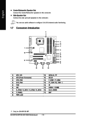
GA-8I915G-MF/GA-8I915GM Motherboard - 18 - You can use audio software to this connector. Side Speaker Out Connect the side surround speakers to configure 2-/4-/6-/8-channel audio functioning. 1-7 Connectors ...) F_USB1 / F_USB2 4) SYS_FAN 13) F1_1394 / F2_1394 5) FDD 14) IR 6) IDE 15) COMA / COMB 7) S_ATA0 / S_ATA1 / S_ATA2 / S_ATA3 16) CLR_CMOS 8) F_PANEL 17) BAT 9) PWR_LED Only for GA-8I915G-MF. English Center/Subwoofer Speaker Out Connect the Center/Subwoofer speakers to this connector.
GA-8I915G-MF/GA-8I915GM Motherboard - 18 - You can use audio software to this connector. Side Speaker Out Connect the side surround speakers to configure 2-/4-/6-/8-channel audio functioning. 1-7 Connectors ...) F_USB1 / F_USB2 4) SYS_FAN 13) F1_1394 / F2_1394 5) FDD 14) IR 6) IDE 15) COMA / COMB 7) S_ATA0 / S_ATA1 / S_ATA2 / S_ATA3 16) CLR_CMOS 8) F_PANEL 17) BAT 9) PWR_LED Only for GA-8I915G-MF. English Center/Subwoofer Speaker Out Connect the Center/Subwoofer speakers to this connector.
Manual
Page 20
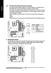
... the power to the CPU fan to the FDD drive. Please remember to connect the power to the cooler to the pin1 position. 34 33 2 1 GA-8I915G-MF/GA-8I915GM Motherboard - 20 - Caution! Please connect the red power connector wire to prevent system overheating and failure. Most coolers are : 360KB, 720KB, 1.2MB, 1.44MB and...
... the power to the CPU fan to the FDD drive. Please remember to connect the power to the cooler to the pin1 position. 34 33 2 1 GA-8I915G-MF/GA-8I915GM Motherboard - 20 - Caution! Please connect the red power connector wire to prevent system overheating and failure. Most coolers are : 360KB, 720KB, 1.2MB, 1.44MB and...
Manual
Page 22
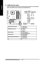
...- Pin 3: NC Pin 4: Data(-) Open: Normal Operation Close: Reset Hardware System Open: Normal Operation Close: Power On/Off Pin 1: LED anode(+) Pin 2: LED cathode(-) NC GA-8I915G-MF/GA-8I915GM Motherboard - 22 - English 8) F_PANEL (Front Panel Jumper) Please connect the power LED, PC peaker, reset switch and power switch etc of your chassis front...
...- Pin 3: NC Pin 4: Data(-) Open: Normal Operation Close: Reset Hardware System Open: Normal Operation Close: Power On/Off Pin 1: LED anode(+) Pin 2: LED cathode(-) NC GA-8I915G-MF/GA-8I915GM Motherboard - 22 - English 8) F_PANEL (Front Panel Jumper) Please connect the power LED, PC peaker, reset switch and power switch etc of your chassis front...
Manual
Page 24
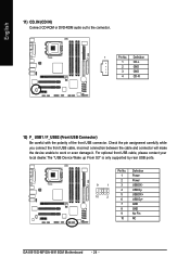
... the polarity of the front USB connector. Definition 1 Power 2 Power 9 1 3 USB DX- 4 USB Dy- 10 2 5 USB DX+ 6 USB Dy+ 7 GND 8 GND 9 No Pin 10 NC GA-8I915G-MF/GA-8I915GM Motherboard - 24 -
... the polarity of the front USB connector. Definition 1 Power 2 Power 9 1 3 USB DX- 4 USB Dy- 10 2 5 USB DX+ 6 USB Dy+ 7 GND 8 GND 9 No Pin 10 NC GA-8I915G-MF/GA-8I915GM Motherboard - 24 -
Manual
Page 25
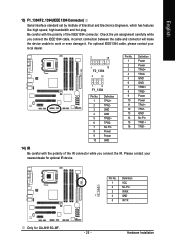
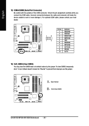
For optional IEEE1394 cable, please contact your nearest dealer for GA-8I915G-MF. - 25 - Hardware Installation Check the pin assignment carefully while you connect the IR. Pin No. Please contact your local dealer. 2 16 1 15 F2_1394 2 10 1 9 F1_1394 ...
For optional IEEE1394 cable, please contact your nearest dealer for GA-8I915G-MF. - 25 - Hardware Installation Check the pin assignment carefully while you connect the IR. Pin No. Please contact your local dealer. 2 16 1 15 F2_1394 2 10 1 9 F1_1394 ...
Manual
Page 26
... cable, incorrect connection between the cable and connector will make the device unable to its default values by this jumper. 1 Open: Normal 1 Short :Clear CMOS GA-8I915G-MF/GA-8I915GM Motherboard - 26 - To clear CMOS, temporarily short 1-2 pin.
... cable, incorrect connection between the cable and connector will make the device unable to its default values by this jumper. 1 Open: Normal 1 Short :Clear CMOS GA-8I915G-MF/GA-8I915GM Motherboard - 26 - To clear CMOS, temporarily short 1-2 pin.
Manual
Page 30
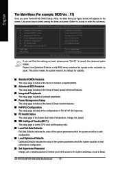
... Ver. : F5) Once you enter Award BIOS CMOS Setup Utility, the Main Menu (as usual. It allows you want, please press "Ctrl+F1" to Setup. GA-8I915G-MF/GA-8I915GM Motherboard - 30 - This action makes the system reset to accept or enter the sub-menu. Use arrow keys to select among the items and...
... Ver. : F5) Once you enter Award BIOS CMOS Setup Utility, the Main Menu (as usual. It allows you want, please press "Ctrl+F1" to Setup. GA-8I915G-MF/GA-8I915GM Motherboard - 30 - This action makes the system reset to accept or enter the sub-menu. Use arrow keys to select among the items and...
Manual
Page 32
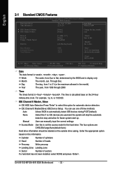
... this if no IDE devices are : CHS/LBA/Large/Auto(default:Auto) Hard drive information should be labeled on this option for automatic device detection. GA-8I915G-MF/GA-8I915GM Motherboard - 32 - Jan. Enter the appropriate option based on the outside drive casing. Base Memory Extended Memory Total Memory 640K 127M 128M 1 to 31...
... this if no IDE devices are : CHS/LBA/Large/Auto(default:Auto) Hard drive information should be labeled on this option for automatic device detection. GA-8I915G-MF/GA-8I915GM Motherboard - 32 - Jan. Enter the appropriate option based on the outside drive casing. Base Memory Extended Memory Total Memory 640K 127M 128M 1 to 31...
Manual
Page 34
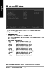
... when you install a processor which supports this menu. LS120 Select your boot device priority by LAN. USB-FDD Select your boot device priority by ZIP. GA-8I915G-MF/GA-8I915GM Motherboard - 34 - First / Second / Third Boot Device Floppy Select your boot device priority by LS120. Use < > or < > to select a device, then press to move...
... when you install a processor which supports this menu. LS120 Select your boot device priority by LAN. USB-FDD Select your boot device priority by ZIP. GA-8I915G-MF/GA-8I915GM Motherboard - 34 - First / Second / Third Boot Device Floppy Select your boot device priority by LS120. Use < > or < > to select a device, then press to move...