Manual
Page 4
...GA-8I865GVMK-775 Motherboard Layout 6 Block Diagram ...7 Chapter 1 Hardware Installation 9 1-1 Considerations Prior to Installation 9 1-2 Feature Summary 10 1-3 Installation of the CPU and Heatsink 11 1-3-1 Installation of the CPU 11 1-3-2 Installation of the Heatsink 12 1-4 Installation of Memory 13 1-5 Installation of Expansion Cards 15 1-6 I/O Back Panel Introduction 16 1-7 Connectors Introduction 17 Chapter 2 BIOS... Setup 27 The Main Menu (For example: BIOS Ver. : E1 28 2-1 Standard CMOS Features 30 2-2 Advanced BIOS Features 32 2-3 ...
...GA-8I865GVMK-775 Motherboard Layout 6 Block Diagram ...7 Chapter 1 Hardware Installation 9 1-1 Considerations Prior to Installation 9 1-2 Feature Summary 10 1-3 Installation of the CPU and Heatsink 11 1-3-1 Installation of the CPU 11 1-3-2 Installation of the Heatsink 12 1-4 Installation of Memory 13 1-5 Installation of Expansion Cards 15 1-6 I/O Back Panel Introduction 16 1-7 Connectors Introduction 17 Chapter 2 BIOS... Setup 27 The Main Menu (For example: BIOS Ver. : E1 28 2-1 Standard CMOS Features 30 2-2 Advanced BIOS Features 32 2-3 ...

Manual
Page 5
Chapter 3 Drivers Installation 45 3-1 Install Chipset Drivers 45 3-2 SoftwareApplication 46 3-3 Software Information 46 3-4 Hardware Information 47 3-5 Contact Us ...47 Chapter 4 Appendix 49 4-1 Unique Software Utilities 49 4-1-1 Xpress Recovery2 Introduction 49 4-1-2 Flash BIOS Method Introduction 51 4-1-3 2- / 4- / 5.1- Channel Audio Function Introduction 60 4-2 Troubleshooting 64 - 5 -
Chapter 3 Drivers Installation 45 3-1 Install Chipset Drivers 45 3-2 SoftwareApplication 46 3-3 Software Information 46 3-4 Hardware Information 47 3-5 Contact Us ...47 Chapter 4 Appendix 49 4-1 Unique Software Utilities 49 4-1-1 Xpress Recovery2 Introduction 49 4-1-2 Flash BIOS Method Introduction 51 4-1-3 2- / 4- / 5.1- Channel Audio Function Introduction 60 4-2 Troubleshooting 64 - 5 -
Manual
Page 6
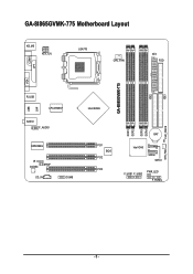
IDE1 GA-8I865GVMK-775 Motherboard Layout KB_MS ATX_12V LGA775 CPU_FAN ATX FDD COMA GA-8I865GVMK-775 DDR1 DDR2 DDR3 DDR4 IDE2 LPT LAN VGA R_USB LPC47M997 USB AUDIO F_AUDIO EP82562G IR CODEC SPDIF CD_IN COMB Intel 865GV PCI1 BIOS PCI2 PCI3 BAT Intel ICH5 SATA0 SATA1 F_USB1 F_USB2 PWR_LED F_PANEL CLR_CMOS SYS_FAN - 6 -
IDE1 GA-8I865GVMK-775 Motherboard Layout KB_MS ATX_12V LGA775 CPU_FAN ATX FDD COMA GA-8I865GVMK-775 DDR1 DDR2 DDR3 DDR4 IDE2 LPT LAN VGA R_USB LPC47M997 USB AUDIO F_AUDIO EP82562G IR CODEC SPDIF CD_IN COMB Intel 865GV PCI1 BIOS PCI2 PCI3 BAT Intel ICH5 SATA0 SATA1 F_USB1 F_USB2 PWR_LED F_PANEL CLR_CMOS SYS_FAN - 6 -

Manual
Page 7
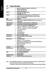
Block Diagram LGA775 Processor CPUCLK+/-(133/200MHz) Host VGA Interface DDR 400/333/266MHz DIMM Intel 865GV GMCH PCI Bus Intel ICH5 EP82562G Dual Channel Memory HCLK (133/200MHz) GMCHCLK (66MHz) 66MHz 33MHz 14.318MHz 48MHz BIOS 2 Serial ATA ATA33/66/100 IDE Channels 3 PCI PCICLK (33MHz) MIC Line-Out Line-In RJ45 CODEC 8 USB Ports LPC47M997 Floppy LPT Port COM Ports PS/2 KB/Mouse 14.318MHz 33MHz - 7 -
Block Diagram LGA775 Processor CPUCLK+/-(133/200MHz) Host VGA Interface DDR 400/333/266MHz DIMM Intel 865GV GMCH PCI Bus Intel ICH5 EP82562G Dual Channel Memory HCLK (133/200MHz) GMCHCLK (66MHz) 66MHz 33MHz 14.318MHz 48MHz BIOS 2 Serial ATA ATA33/66/100 IDE Channels 3 PCI PCICLK (33MHz) MIC Line-Out Line-In RJ45 CODEC 8 USB Ports LPC47M997 Floppy LPT Port COM Ports PS/2 KB/Mouse 14.318MHz 33MHz - 7 -
Manual
Page 10
...Memory Slots IDE Connections FDD Connections Onboard SATA Peripherals Onboard VGA Onboard LAN Onboard Audio I/O Control Hardware Monitor BIOS Additional Features Form Factor Š Supports the latest Intel® Pentium® 4 LGA775 CPU Š...138; CPU / System temperature detection Š CPU / System fan speed detection Š Use of licensed AWARD BIOS Š Supports Q-Flash Š Supports @BIOS Š Micro ATX form factor; 24.4cm x 24.4cm (Note) Due to 4GB memory) (Note)...memory size will instead be shown as 3.xxGB memory during system startup. GA-8I865GVMK-775 Motherboard - 10 -
...Memory Slots IDE Connections FDD Connections Onboard SATA Peripherals Onboard VGA Onboard LAN Onboard Audio I/O Control Hardware Monitor BIOS Additional Features Form Factor Š Supports the latest Intel® Pentium® 4 LGA775 CPU Š...138; CPU / System temperature detection Š CPU / System fan speed detection Š Use of licensed AWARD BIOS Š Supports Q-Flash Š Supports @BIOS Š Micro ATX form factor; 24.4cm x 24.4cm (Note) Due to 4GB memory) (Note)...memory size will instead be shown as 3.xxGB memory during system startup. GA-8I865GVMK-775 Motherboard - 10 -

Manual
Page 11
... and forefinger, carefully place it enabled - Please make sure that might cause damage to system use, otherwise overheating and permanent damage of the CPU socket. BIOS: A BIOS that supports HT Technology - Align the indented corner of Hyper-Threading Technology for the peripherals. Please set beyond the proper specifications, please do so according...
... and forefinger, carefully place it enabled - Please make sure that might cause damage to system use, otherwise overheating and permanent damage of the CPU socket. BIOS: A BIOS that supports HT Technology - Align the indented corner of Hyper-Threading Technology for the peripherals. Please set beyond the proper specifications, please do so according...

Manual
Page 13
... memory module vertically into the DIMM socket. It is recommended that they can only fit in one direction. The motherboard supports DDR memory modules, whereby BIOS will automatically detect memory capacity and specifications. Then push it down.
... memory module vertically into the DIMM socket. It is recommended that they can only fit in one direction. The motherboard supports DDR memory modules, whereby BIOS will automatically detect memory capacity and specifications. Then push it down.
Manual
Page 14
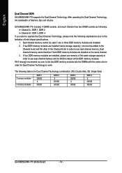
... is for BIOS to the limitation of Memory Bus will double. The following explanations due to detect all the DDR memory modules. Dual channel memory cannot function if both DDR memory modules are installed. 2. After operating the Dual Channel Technology, the bandwidth of Intel chipset specifications. 1. English Dual Channel DDR GA-8I865GVMK-775 supports...
... is for BIOS to the limitation of Memory Bus will double. The following explanations due to detect all the DDR memory modules. Dual channel memory cannot function if both DDR memory modules are installed. 2. After operating the Dual Channel Technology, the bandwidth of Intel chipset specifications. 1. English Dual Channel DDR GA-8I865GVMK-775 supports...

Manual
Page 15
... indeed seated in motherboard. 4. Installing a PCI expansion card: - 15 - Remove your computer's chassis cover, screws and slot bracket from BIOS. 8. Be sure the metal contacts on the computer, if necessary, setup BIOS utility of expansion card from the computer. 3. Hardware Installation Read the related expansion card's instruction document before install the expansion...
... indeed seated in motherboard. 4. Installing a PCI expansion card: - 15 - Remove your computer's chassis cover, screws and slot bracket from BIOS. 8. Be sure the metal contacts on the computer, if necessary, setup BIOS utility of expansion card from the computer. 3. Hardware Installation Read the related expansion card's instruction document before install the expansion...
Manual
Page 20
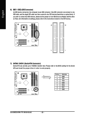
...). Pin No. Please refer to the BIOS setting for information on settings, please refer to the instructions located on the IDE device). 40 39 2 1 7) SATA0 / SATA1 (Serial ATA Connector) Serial ATA can then connect to 150MB/s transfer rate. Definition 7 1 1 GND 2 TXP 3 TXN 4 GND 5 RXN 6 RXP 7 GND GA-8I865GVMK-775 Motherboard - 20 - One IDE connector...
...). Pin No. Please refer to the BIOS setting for information on settings, please refer to the instructions located on the IDE device). 40 39 2 1 7) SATA0 / SATA1 (Serial ATA Connector) Serial ATA can then connect to 150MB/s transfer rate. Definition 7 1 1 GND 2 TXP 3 TXN 4 GND 5 RXN 6 RXP 7 GND GA-8I865GVMK-775 Motherboard - 20 - One IDE connector...

Manual
Page 27
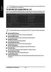
..., pushing the button during the BIOS POST (Power-On Self Test) will take you to select item Select Item Main Menu - The CMOS SETUP saves the configuration in the event that BIOS needs to a new BIOS, either Gigabyte's Q-Flash or @BIOS utility can enter the BIOS setup screen by pressing "Ctrl ...+ F1". You can be reset to pop up BIOS for the highlighted item. Quit and not save the current BIOS to a disk in the CMOS ...
..., pushing the button during the BIOS POST (Power-On Self Test) will take you to select item Select Item Main Menu - The CMOS SETUP saves the configuration in the event that BIOS needs to a new BIOS, either Gigabyte's Q-Flash or @BIOS utility can enter the BIOS setup screen by pressing "Ctrl ...+ F1". You can be reset to pop up BIOS for the highlighted item. Quit and not save the current BIOS to a disk in the CMOS ...
Manual
Page 28
GA-8I865GVMK-775 Motherboard - 28 - If you can't find the setting you enter Award BIOS CMOS Setup Utility, the Main Menu (as figure below) will appear on the screen. CMOS Setup Utility-Copyright (C) 1984-2005 Award Software ` Standard CMOS Features ` Advanced BIOS Features ` Integrated Peripherals ` Power ... the advanced option hidden. „ Standard CMOS Features This setup page includes all the items in standard compatible BIOS. „ Advanced BIOS Features This setup page includes all the items of Award special enhanced features. „ Integrated Peripherals This setup ...
GA-8I865GVMK-775 Motherboard - 28 - If you can't find the setting you enter Award BIOS CMOS Setup Utility, the Main Menu (as figure below) will appear on the screen. CMOS Setup Utility-Copyright (C) 1984-2005 Award Software ` Standard CMOS Features ` Advanced BIOS Features ` Integrated Peripherals ` Power ... the advanced option hidden. „ Standard CMOS Features This setup page includes all the items in standard compatible BIOS. „ Advanced BIOS Features This setup page includes all the items of Award special enhanced features. „ Integrated Peripherals This setup ...

Manual
Page 29
It allows you to limit access to the system and Setup, or just to CMOS and exit setup. „ Exit Without Saving Abandon all CMOS value changes and exit setup. - 29 - It allows you to limit access to the system. „ Save & Exit Setup Save CMOS value settings to Setup. „ Set User Password Change, set , or disable password. BIOS Setup English „ Load Optimized Defaults Optimized Defaults indicates the value of the system parameters which the system would be in best performance configuration. „ Set Supervisor Password Change, set , or disable password.
It allows you to limit access to the system and Setup, or just to CMOS and exit setup. „ Exit Without Saving Abandon all CMOS value changes and exit setup. - 29 - It allows you to limit access to the system. „ Save & Exit Setup Save CMOS value settings to Setup. „ Set User Password Change, set , or disable password. BIOS Setup English „ Load Optimized Defaults Optimized Defaults indicates the value of the system parameters which the system would be in best performance configuration. „ Set Supervisor Password Change, set , or disable password.
Manual
Page 30
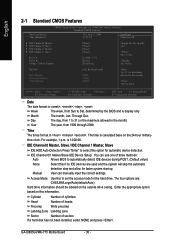
...Dec. Day The day, from 1 to 31 (or the maximum allowed in the month) Year The year, from Sun to Sat, determined by the BIOS and is 13:00:00. For example, 1 p.m. IDE Channel 0/1 Master/Slave IDE Device Setup. Manual User can use one of sectors If a hard...Cylinder Number of cylinders Head Number of heads Precomp Write precomp Landing Zone Landing zone Sector Number of three methods: Auto Allows BIOS to 31 (or maximum allowed in . GA-8I865GVMK-775 Motherboard - 30 - Jan. The four options are used and the system will skip the automatic detection step and allow ...
...Dec. Day The day, from 1 to 31 (or the maximum allowed in the month) Year The year, from Sun to Sat, determined by the BIOS and is 13:00:00. For example, 1 p.m. IDE Channel 0/1 Master/Slave IDE Device Setup. Manual User can use one of sectors If a hard...Cylinder Number of cylinders Head Number of heads Precomp Write precomp Landing Zone Landing zone Sector Number of three methods: Auto Allows BIOS to 31 (or maximum allowed in . GA-8I865GVMK-775 Motherboard - 30 - Jan. The four options are used and the system will skip the automatic detection step and allow ...

Manual
Page 31
... 1.44M, 3.5" 3.5 inch double-sided drive; 1.44M byte capacity. 2.88M, 3.5" 3.5 inch double-sided drive; 2.88M byte capacity. The value of the BIOS. None 360K, 5.25" No floppy drive installed 5.25 inch PC-type standard drive; 360K byte capacity. 1.2M, 5.25" 5.25 inch AT-type high-density...; 1.2M byte capacity (3.5 inch when 3 Mode is determined by POST (Power On Self Test) of the base memory is 3 mode Floppy Drive. BIOS Setup Floppy 3 Mode Support (for Japan Area) Disabled Normal Floppy Drive. (Default value) Drive A Drive B Drive A is typically 512K for systems ...
... 1.44M, 3.5" 3.5 inch double-sided drive; 1.44M byte capacity. 2.88M, 3.5" 3.5 inch double-sided drive; 2.88M byte capacity. The value of the BIOS. None 360K, 5.25" No floppy drive installed 5.25 inch PC-type standard drive; 360K byte capacity. 1.2M, 5.25" 5.25 inch AT-type high-density...; 1.2M byte capacity (3.5 inch when 3 Mode is determined by POST (Power On Self Test) of the base memory is 3 mode Floppy Drive. BIOS Setup Floppy 3 Mode Support (for Japan Area) Disabled Normal Floppy Drive. (Default value) Drive A Drive B Drive A is typically 512K for systems ...
Manual
Page 32
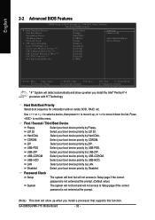
... up when you install a processor that supports this menu. Disabled Select your boot device priority by USB-FDD. GA-8I865GVMK-775 Motherboard - 32 - English 2-2 Advanced BIOS Features CMOS Setup Utility-Copyright (C) 1984-2005 Award Software Advanced BIOS Features ` Hard Disk Boot Priority First Boot Device Second Boot Device Third Boot Device Password Check # CPU Hyper...
... up when you install a processor that supports this menu. Disabled Select your boot device priority by USB-FDD. GA-8I865GVMK-775 Motherboard - 32 - English 2-2 Advanced BIOS Features CMOS Setup Utility-Copyright (C) 1984-2005 Award Software Advanced BIOS Features ` Hard Disk Boot Priority First Boot Device Second Boot Device Third Boot Device Password Check # CPU Hyper...

Manual
Page 33
BIOS Setup On-Chip Frame Buffer Size 1MB 4MB 8MB 16MB 32MB Set on -chip frame buffer size to 1MB. Set on -chip frame buffer size ...
BIOS Setup On-Chip Frame Buffer Size 1MB 4MB 8MB 16MB 32MB Set on -chip frame buffer size to 1MB. Set on -chip frame buffer size ...

Manual
Page 35
... Auto detect AC97 audio function. (Default value) Disable AC97 audio function. Enable onboard Serial port 2 and address is 3E8/IRQ4. BIOS Setup Enabled Enable this function if you are not using onboard USB 2.0 feature. Disable onboard Serial port 2. - 35 - English USB...is 2E8/IRQ3. Enabled Disabled Enable USB 2.0 controller. (Default value) Disable USB 2.0 controller. Onboard Serial Port 1 Auto 3F8/IRQ4 BIOS will automatically setup the port 1 address. USB Keyboard Support Enabled Enable USB keyboard support. Double click on mouse left button to power...
... Auto detect AC97 audio function. (Default value) Disable AC97 audio function. Enable onboard Serial port 2 and address is 3E8/IRQ4. BIOS Setup Enabled Enable this function if you are not using onboard USB 2.0 feature. Disable onboard Serial port 2. - 35 - English USB...is 2E8/IRQ3. Enabled Disabled Enable USB 2.0 controller. (Default value) Disable USB 2.0 controller. Onboard Serial Port 1 Auto 3F8/IRQ4 BIOS will automatically setup the port 1 address. USB Keyboard Support Enabled Enable USB keyboard support. Double click on mouse left button to power...

Manual
Page 37
... least 1A on the LAN can awake the system from any suspend state. Enabled Enable Modem Ring On / Wake On LAN function. (Default value) - 37 - BIOS Setup Enabled Enable PME as wake up event. (Default value) ModemRingOn/WakeOnLan An incoming call via modem can awake the system from any suspend state...
... least 1A on the LAN can awake the system from any suspend state. Enabled Enable Modem Ring On / Wake On LAN function. (Default value) - 37 - BIOS Setup Enabled Enable PME as wake up event. (Default value) ModemRingOn/WakeOnLan An incoming call via modem can awake the system from any suspend state...
Manual
Page 39
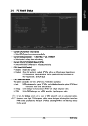
... Speed (RPM) Detect CPU/SYSTEM Fan speed status automatically. Current Voltage(V) Vcore / +3.3V / +5V / +12V / DDR25V Detect system's voltage status automatically. Auto BIOS autodetects the type of CPU fan you installed and sets the optimal CPU Smart FAN control mode for CPU fans with Easy Tune based on... CPU temperature. BIOS Setup CPU Smart FAN Control Disabled Disable this function is enabled. PWM Set to Voltage when you use a CPU fan with a 4-pin ...
... Speed (RPM) Detect CPU/SYSTEM Fan speed status automatically. Current Voltage(V) Vcore / +3.3V / +5V / +12V / DDR25V Detect system's voltage status automatically. Auto BIOS autodetects the type of CPU fan you installed and sets the optimal CPU Smart FAN control mode for CPU fans with Easy Tune based on... CPU temperature. BIOS Setup CPU Smart FAN Control Disabled Disable this function is enabled. PWM Set to Voltage when you use a CPU fan with a 4-pin ...


