Manual
Page 4
...GA-8I865GM-775/GA-8I865GMF-775 Motherboard Layout 6 Block Diagram ...7 Chapter 1 Hardware Installation 9 1-1 Considerations Prior to Installation 9 1-2 Feature Summary 10 1-3 Installation of the CPU and Heatsink 11 1-3-1 Installation of the CPU 11 1-3-2 Installation of the Heatsink 12 1-4 Installation of Memory 13 1-5 Installation of Expansion Cards 15 1-6 I/O Back Panel Introduction 16 1-7 Connectors Introduction 17 Chapter 2 BIOS... Setup 27 The Main Menu (For example: BIOS Ver. : E4 28 2-1 Standard CMOS Features 30 2-2 Advanced BIOS Features 32 2-3 ...
...GA-8I865GM-775/GA-8I865GMF-775 Motherboard Layout 6 Block Diagram ...7 Chapter 1 Hardware Installation 9 1-1 Considerations Prior to Installation 9 1-2 Feature Summary 10 1-3 Installation of the CPU and Heatsink 11 1-3-1 Installation of the CPU 11 1-3-2 Installation of the Heatsink 12 1-4 Installation of Memory 13 1-5 Installation of Expansion Cards 15 1-6 I/O Back Panel Introduction 16 1-7 Connectors Introduction 17 Chapter 2 BIOS... Setup 27 The Main Menu (For example: BIOS Ver. : E4 28 2-1 Standard CMOS Features 30 2-2 Advanced BIOS Features 32 2-3 ...
Manual
Page 5
Chapter 3 Drivers Installation 45 3-1 Install Chipset Drivers 45 3-2 Software Application 46 3-3 Software Information 46 3-4 Hardware Information 47 3-5 Contact Us ...47 Chapter 4 Appendix 49 4-1 Unique Software Utilities 49 4-1-1 Xpress Recovery Introduction 49 4-1-2 Flash BIOS Method Introduction 52 4-1-3 2- / 4- / 5.1- Channel Audio Function Introduction 61 4-2 Troubleshooting 65 - 5 -
Chapter 3 Drivers Installation 45 3-1 Install Chipset Drivers 45 3-2 Software Application 46 3-3 Software Information 46 3-4 Hardware Information 47 3-5 Contact Us ...47 Chapter 4 Appendix 49 4-1 Unique Software Utilities 49 4-1-1 Xpress Recovery Introduction 49 4-1-2 Flash BIOS Method Introduction 52 4-1-3 2- / 4- / 5.1- Channel Audio Function Introduction 61 4-2 Troubleshooting 65 - 5 -
Manual
Page 6
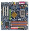
IDE1 GA-8I865GM-775/GA-8I865GMF-775 Motherboard Layout KB_MS ATX_12V LGA775 CPU_FAN ATX FDD COMA GA-8I865GM-775 (or GA-8I865GMF-775*) DDR1 DDR2 DDR3 DDR4 IDE2 LPT VGA R_USB USB LAN F_AUDIO LPC47M997 IR AUDIO BIOS SPDIF Marvell 8001 CODEC CD_IN AGP COMB Intel 865G BAT PCI1 PCI2 TSB43AB23* PCI3 F2_1394* F1_1394* Intel ICH5 SATA1 SATA0 F_USB1 F_USB2 PWR_LED F_PANEL CLR_CMOS SYS_FAN * Only for GA-8I865GMF-775. - 6 -
IDE1 GA-8I865GM-775/GA-8I865GMF-775 Motherboard Layout KB_MS ATX_12V LGA775 CPU_FAN ATX FDD COMA GA-8I865GM-775 (or GA-8I865GMF-775*) DDR1 DDR2 DDR3 DDR4 IDE2 LPT VGA R_USB USB LAN F_AUDIO LPC47M997 IR AUDIO BIOS SPDIF Marvell 8001 CODEC CD_IN AGP COMB Intel 865G BAT PCI1 PCI2 TSB43AB23* PCI3 F2_1394* F1_1394* Intel ICH5 SATA1 SATA0 F_USB1 F_USB2 PWR_LED F_PANEL CLR_CMOS SYS_FAN * Only for GA-8I865GMF-775. - 6 -

Manual
Page 7
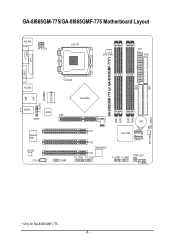
Block Diagram LGA775 Processor CPUCLK+/-(133/200MHz) AGP 8X/4X VGA AGPCLK (66MHz) PCI Bus TSB43AB23* Marvell 8001 Host Interface DDR 400/333/266MHz DIMM Intel 865G GMCH Dual Channel Memory HCLK (133/200MHz) GMCHCLK (66MHz) 66MHz 33MHz 14.318MHz 48MHz BIOS Intel 2 Serial ATA ICH5 ATA33/66/100 IDE Channels RJ45 3 IEEE1394* CODEC LPC47M997 Floppy LPT Port COM Port 3 PCI 8 USB Ports PS/2 KB/Mouse 14.318MHz 33MHz MIC Line-Out Line-In PCICLK (33MHz) * Only for GA-8I865GMF-775. - 7 -
Block Diagram LGA775 Processor CPUCLK+/-(133/200MHz) AGP 8X/4X VGA AGPCLK (66MHz) PCI Bus TSB43AB23* Marvell 8001 Host Interface DDR 400/333/266MHz DIMM Intel 865G GMCH Dual Channel Memory HCLK (133/200MHz) GMCHCLK (66MHz) 66MHz 33MHz 14.318MHz 48MHz BIOS Intel 2 Serial ATA ICH5 ATA33/66/100 IDE Channels RJ45 3 IEEE1394* CODEC LPC47M997 Floppy LPT Port COM Port 3 PCI 8 USB Ports PS/2 KB/Mouse 14.318MHz 33MHz MIC Line-Out Line-In PCICLK (33MHz) * Only for GA-8I865GMF-775. - 7 -
Manual
Page 10
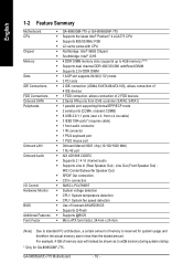
... Motherboard CPU Chipset Memory Slots IDE Connections FDD Connections Onboard SATA Peripherals Onboard LAN Onboard Audio I/O Control Hardware Monitor BIOS Additional Features Form Factor Š GA-8I865GM-775 or GA-8I865GMF-775 Š Supports the latest Intel® Pentium® 4 LGA775 CPU Š Supports 800/533MHz FSB Š...174; ICH5 Š 4 DDR DIMM memory slots (supports up to standard PC architecture, a certain amount of memory is reserved for GA-8I865GMF-775. For example, 4 GB of memory size will instead be shown as 3.xxGB memory during system startup. * Only for system usage...
... Motherboard CPU Chipset Memory Slots IDE Connections FDD Connections Onboard SATA Peripherals Onboard LAN Onboard Audio I/O Control Hardware Monitor BIOS Additional Features Form Factor Š GA-8I865GM-775 or GA-8I865GMF-775 Š Supports the latest Intel® Pentium® 4 LGA775 CPU Š Supports 800/533MHz FSB Š...174; ICH5 Š 4 DDR DIMM memory slots (supports up to standard PC architecture, a certain amount of memory is reserved for GA-8I865GMF-775. For example, 4 GB of memory size will instead be shown as 3.xxGB memory during system startup. * Only for system usage...

Manual
Page 11
... Hyper-Threading Technology for HT Technology 1-3-1 Installation of the CPU. It is not recommended that supports HT Technology and has it into its original position. BIOS: A BIOS that the system bus frequency be set the CPU host frequency in a straight and downwards motion. Align the indented corner of the following conditions: 1. Fig...
... Hyper-Threading Technology for HT Technology 1-3-1 Installation of the CPU. It is not recommended that supports HT Technology and has it into its original position. BIOS: A BIOS that the system bus frequency be set the CPU host frequency in a straight and downwards motion. Align the indented corner of the following conditions: 1. Fig...

Manual
Page 13
... DIMM socket has a notch, so the DIMM memory module can be inserted only in only one direction. The motherboard supports DDR II memory modules, whereby BIOS will automatically detect memory capacity and specifications. If you wish to lock the DIMM module. Insert the DIMM memory module vertically into the DIMM socket...
... DIMM socket has a notch, so the DIMM memory module can be inserted only in only one direction. The motherboard supports DDR II memory modules, whereby BIOS will automatically detect memory capacity and specifications. If you wish to lock the DIMM module. Insert the DIMM memory module vertically into the DIMM socket...
Manual
Page 14
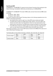
... installed. 2. We'll strongly recommend our user to slot two DDR memory modules into the DIMMs with the same color in order to work. GA-8I865GM-775 / GA-8I865GMF-775 includes 4 DIMM sockets, and each Channel has two DIMM sockets as following: Channel A : DDR 1, DDR 2 Channel B : DDR 3, ... the Dual Channel Technology, please note the following table is for BIOS to 6.4GB/s(DDR400). If four DDR memory modules are installed on the same channel. 3. English Dual Channel DDR GA-8I865GM-775 / GA-8I865GMF-775 supports the Dual Channel Technology. The following explanations due to the ...
... installed. 2. We'll strongly recommend our user to slot two DDR memory modules into the DIMMs with the same color in order to work. GA-8I865GM-775 / GA-8I865GMF-775 includes 4 DIMM sockets, and each Channel has two DIMM sockets as following: Channel A : DDR 1, DDR 2 Channel B : DDR 3, ... the Dual Channel Technology, please note the following table is for BIOS to 6.4GB/s(DDR400). If four DDR memory modules are installed on the same channel. 3. English Dual Channel DDR GA-8I865GM-775 / GA-8I865GMF-775 supports the Dual Channel Technology. The following explanations due to the ...

Manual
Page 15
... bracket of the AGP slot when you try to the onboard AGP slot and press firmly down on the computer, if necessary, setup BIOS utility of expansion card from BIOS. 8. Please align the VGA card to install/uninstall the VGA card. Read the related expansion card's instruction document before install the expansion...
... bracket of the AGP slot when you try to the onboard AGP slot and press firmly down on the computer, if necessary, setup BIOS utility of expansion card from BIOS. 8. Please align the VGA card to install/uninstall the VGA card. Read the related expansion card's instruction document before install the expansion...
Manual
Page 20
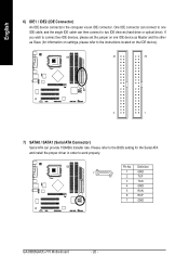
Definition 7 1 1 GND 2 TXP 3 TXN 4 GND 5 RXN 6 RXP 7 GND GA-8I865GM(F)-775 Motherboard - 20 - If you wish to two IDE devices (hard drive or optical drive). One IDE connector can then connect to connect two IDE devices, ... jumper on the IDE device). 40 39 2 1 7) SATA0 / SATA1 (Serial ATA Connector) Serial ATA can provide 150MB/s transfer rate. Pin No. Please refer to the BIOS setting for information on settings, please refer to the instructions located on one IDE cable, and the single IDE cable can connect to one IDE...
Definition 7 1 1 GND 2 TXP 3 TXN 4 GND 5 RXN 6 RXP 7 GND GA-8I865GM(F)-775 Motherboard - 20 - If you wish to two IDE devices (hard drive or optical drive). One IDE connector can then connect to connect two IDE devices, ... jumper on the IDE device). 40 39 2 1 7) SATA0 / SATA1 (Serial ATA Connector) Serial ATA can provide 150MB/s transfer rate. Pin No. Please refer to the BIOS setting for information on settings, please refer to the instructions located on one IDE cable, and the single IDE cable can connect to one IDE...

Manual
Page 27
... exit the Help Window press . - 27 - When the power is a Windows-based utility that BIOS needs to be used. If you to a new BIOS, either Gigabyte's Q-Flash or @BIOS utility can enter the BIOS setup screen by pressing "Ctrl + F1". When the power is displayed at the bottom of the ...motherboard. BIOS Setup Status Page Setup Menu / Option Page Setup Menu Press F1 to pop up BIOS for Main Menu Main ...
... exit the Help Window press . - 27 - When the power is a Windows-based utility that BIOS needs to be used. If you to a new BIOS, either Gigabyte's Q-Flash or @BIOS utility can enter the BIOS setup screen by pressing "Ctrl + F1". When the power is displayed at the bottom of the ...motherboard. BIOS Setup Status Page Setup Menu / Option Page Setup Menu Press F1 to pop up BIOS for Main Menu Main ...

Manual
Page 28
...press to search the advanced option hidden. „ Standard CMOS Features This setup page includes all the items in standard compatible BIOS. „ Advanced BIOS Features This setup page includes all the items of Award special enhanced features. „ Integrated Peripherals This setup page includes ...Safe Defaults indicates the value of the system parameters which the system would be in safe configuration. GA-8I865GM(F)-775 Motherboard - 28 - If you can't find the setting you enter Award BIOS CMOS Setup Utility, the Main Menu (as figure below) will appear on the screen. CMOS Setup...
...press to search the advanced option hidden. „ Standard CMOS Features This setup page includes all the items in standard compatible BIOS. „ Advanced BIOS Features This setup page includes all the items of Award special enhanced features. „ Integrated Peripherals This setup page includes ...Safe Defaults indicates the value of the system parameters which the system would be in safe configuration. GA-8I865GM(F)-775 Motherboard - 28 - If you can't find the setting you enter Award BIOS CMOS Setup Utility, the Main Menu (as figure below) will appear on the screen. CMOS Setup...

Manual
Page 29
It allows you to limit access to the system and Setup, or just to CMOS and exit setup. „ Exit Without Saving Abandon all CMOS value changes and exit setup. - 29 - BIOS Setup English „ Load Optimized Defaults Optimized Defaults indicates the value of the system parameters which the system would be in best performance configuration. „ Set Supervisor Password Change, set , or disable password. It allows you to limit access to the system. „ Save & Exit Setup Save CMOS value settings to Setup. „ Set User Password Change, set , or disable password.
It allows you to limit access to the system and Setup, or just to CMOS and exit setup. „ Exit Without Saving Abandon all CMOS value changes and exit setup. - 29 - BIOS Setup English „ Load Optimized Defaults Optimized Defaults indicates the value of the system parameters which the system would be in best performance configuration. „ Set Supervisor Password Change, set , or disable password. It allows you to limit access to the system. „ Save & Exit Setup Save CMOS value settings to Setup. „ Set User Password Change, set , or disable password.
Manual
Page 30
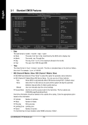
.... The time is , , , . Cylinder Number of cylinders Head Number of heads Precomp Write precomp Landing Zone Landing zone Sector Number of three methods: Auto Allows BIOS to set the access mode for faster system start up. IDE Channel 0/1 Master/Slave IDE Device Setup. The four options are used and the system... Sun. to Dec. Jan. Week Month The week, from 1999 through 2098 Time The times format in the month) 1999 to Sat, determined by the BIOS and is 13:00:00. is display only The month, Jan. GA-8I865GM(F)-775 Motherboard - 30 -
.... The time is , , , . Cylinder Number of cylinders Head Number of heads Precomp Write precomp Landing Zone Landing zone Sector Number of three methods: Auto Allows BIOS to set the access mode for faster system start up. IDE Channel 0/1 Master/Slave IDE Device Setup. The four options are used and the system... Sun. to Dec. Jan. Week Month The week, from 1999 through 2098 Time The times format in the month) 1999 to Sat, determined by the BIOS and is 13:00:00. is display only The month, Jan. GA-8I865GM(F)-775 Motherboard - 30 -

Manual
Page 31
... with 512K memory installed on the motherboard, or 640K for any error that may be detected and you will be prompted. The value of the BIOS will not stop for a disk error; Drive B is Enabled). 720K, 3.5" 3.5 inch double-sided drive; 720K byte capacity 1.44M, 3.5" 3.5 ...inch double-sided drive; 1.44M byte capacity. 2.88M, 3.5" 3.5 inch double-sided drive; 2.88M byte capacity. All Errors Whenever the BIOS detects a non-fatal error the system will be stopped. it will stop for all other errors. Base Memory The POST of the base memory is...
... with 512K memory installed on the motherboard, or 640K for any error that may be detected and you will be prompted. The value of the BIOS will not stop for a disk error; Drive B is Enabled). 720K, 3.5" 3.5 inch double-sided drive; 720K byte capacity 1.44M, 3.5" 3.5 ...inch double-sided drive; 1.44M byte capacity. 2.88M, 3.5" 3.5 inch double-sided drive; 2.88M byte capacity. All Errors Whenever the BIOS detects a non-fatal error the system will be stopped. it will stop for all other errors. Base Memory The POST of the base memory is...
Manual
Page 32
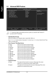
... CMOS Setup Utility-Copyright (C) 1984-2004 Award Software Advanced BIOS Features ` Hard Disk Boot Priority First Boot Device Second Boot Device Third Boot Device Password Check # CPU Hyper-Threading Limit CPUID Max. Press to Setup ... by LS120. First / Second / Third Boot Device Floppy Select your boot device priority by Hard Disk. ZIP Select your boot device priority by USB-FDD. GA-8I865GM(F)-775 Motherboard - 32 - to 3 On-Chip Frame Buffer Size [Press Enter] [Floppy] [Hard Disk] [CDROM] [Setup] [Enabled] [Enabled] [16MB] Item Help Menu Level` Select Hard Disk...
... CMOS Setup Utility-Copyright (C) 1984-2004 Award Software Advanced BIOS Features ` Hard Disk Boot Priority First Boot Device Second Boot Device Third Boot Device Password Check # CPU Hyper-Threading Limit CPUID Max. Press to Setup ... by LS120. First / Second / Third Boot Device Floppy Select your boot device priority by Hard Disk. ZIP Select your boot device priority by USB-FDD. GA-8I865GM(F)-775 Motherboard - 32 - to 3 On-Chip Frame Buffer Size [Press Enter] [Floppy] [Hard Disk] [CDROM] [Setup] [Enabled] [Enabled] [16MB] Item Help Menu Level` Select Hard Disk...

Manual
Page 33
... Hyper Threading. to 3 Enabled Disabled Limit CPUID Maximum value to 32MB. - 33 - Limit CPUID Max. English CPU Hyper-Threading Enabled Enables CPU Hyper Threading Feature. BIOS Setup Please note that this feature is only working Disabled for windows XP.
... Hyper Threading. to 3 Enabled Disabled Limit CPUID Maximum value to 32MB. - 33 - Limit CPUID Max. English CPU Hyper-Threading Enabled Enables CPU Hyper Threading Feature. BIOS Setup Please note that this feature is only working Disabled for windows XP.
Manual
Page 35
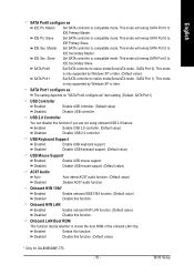
...This mode will remap SATA Port 0 to compatible mode. USB 2.0 Controller You can disable this function. (Default value) * Only for GA-8I865GMF-775. - 35 - Enabled Enable USB 2.0 controller. (Default value) Disabled Disable USB 2.0 controller. USB Keyboard Support Enabled Enable USB keyboard support... Disabled Disable this function if you are not using onboard USB 2.0 feature. Slave Set SATA controller to IDE Secondary Master. BIOS Setup SATA Port 0). This mode will remap SATA Port 0 to compatible mode. IDE Sec. This mode is only supported...
...This mode will remap SATA Port 0 to compatible mode. USB 2.0 Controller You can disable this function. (Default value) * Only for GA-8I865GMF-775. - 35 - Enabled Enable USB 2.0 controller. (Default value) Disabled Disable USB 2.0 controller. USB Keyboard Support Enabled Enable USB keyboard support... Disabled Disable this function if you are not using onboard USB 2.0 feature. Slave Set SATA controller to IDE Secondary Master. BIOS Setup SATA Port 0). This mode will remap SATA Port 0 to compatible mode. IDE Sec. This mode is only supported...

Manual
Page 36
...address is 2F8. 3E8/IRQ4 Enable onboard Serial port 1 and address is 3E8. 2E8/IRQ3 Enable onboard Serial port 1 and address is 2E8. GA-8I865GM(F)-775 Motherboard - 36 - Mouse/Any KEY Press any key to 1. ASKIR Set onboard I/O chip UART to power on mouse left button to ASKIR....7+ECP Using Parallel port as Enhanced Parallel Port 1.9 and ECP mode. Onboard Serial Port 1 Auto BIOS will available when "UART Mode Select" doesn't set at Normal. Onboard Serial Port 2 Auto BIOS will automatically setup the port 1 address. 3F8/IRQ4 Enable onboard Serial port 2 and address is...
...address is 2F8. 3E8/IRQ4 Enable onboard Serial port 1 and address is 3E8. 2E8/IRQ3 Enable onboard Serial port 1 and address is 2E8. GA-8I865GM(F)-775 Motherboard - 36 - Mouse/Any KEY Press any key to 1. ASKIR Set onboard I/O chip UART to power on mouse left button to ASKIR....7+ECP Using Parallel port as Enhanced Parallel Port 1.9 and ECP mode. Onboard Serial Port 1 Auto BIOS will available when "UART Mode Select" doesn't set at Normal. Onboard Serial Port 2 Auto BIOS will automatically setup the port 1 address. 3F8/IRQ4 Enable onboard Serial port 2 and address is...

Manual
Page 37
Press power button 4 sec. Disabled Disable this function. BIOS Setup English 2-4 Power Management Setup CMOS Setup Utility-Copyright (C) 1984-2004 Award Software Power Management Setup ACPI Suspend Type Power LED in S1 state Off ...
Press power button 4 sec. Disabled Disable this function. BIOS Setup English 2-4 Power Management Setup CMOS Setup Utility-Copyright (C) 1984-2004 Award Software Power Management Setup ACPI Suspend Type Power LED in S1 state Off ...


