Manual
Page 1
GA-8I865GM-775 / GA-8I865GMF-775 Intel® Pentium® 4 LGA775 Processor Motherboard User's Manual Rev. 1001 12ME-8I865GMT-1001
GA-8I865GM-775 / GA-8I865GMF-775 Intel® Pentium® 4 LGA775 Processor Motherboard User's Manual Rev. 1001 12ME-8I865GMT-1001
Manual
Page 2
Motherboard GA-8I865GM-775 / GA-8I865GMF-775 Sep. 5, 2004 Motherboard GA-8I865GM-775 / GA-8I865GMF-775 Sep. 5, 2004
Motherboard GA-8I865GM-775 / GA-8I865GMF-775 Sep. 5, 2004 Motherboard GA-8I865GM-775 / GA-8I865GMF-775 Sep. 5, 2004
Manual
Page 4
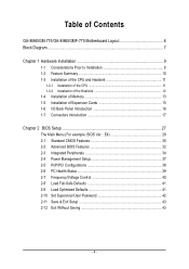
Table of Contents GA-8I865GM-775/GA-8I865GMF-775 Motherboard Layout 6 Block Diagram ...7 Chapter 1 Hardware Installation 9 1-1 Considerations Prior to Installation 9 1-2 Feature Summary 10 1-3 Installation of the CPU and Heatsink 11 1-3-1 Installation of the CPU ...
Table of Contents GA-8I865GM-775/GA-8I865GMF-775 Motherboard Layout 6 Block Diagram ...7 Chapter 1 Hardware Installation 9 1-1 Considerations Prior to Installation 9 1-2 Feature Summary 10 1-3 Installation of the CPU and Heatsink 11 1-3-1 Installation of the CPU ...
Manual
Page 6
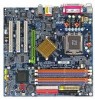
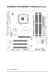
IDE1 GA-8I865GM-775/GA-8I865GMF-775 Motherboard Layout KB_MS ATX_12V LGA775 CPU_FAN ATX FDD COMA GA-8I865GM-775 (or GA-8I865GMF-775*) DDR1 DDR2 DDR3 DDR4 IDE2 LPT VGA R_USB USB LAN F_AUDIO LPC47M997 IR AUDIO BIOS SPDIF Marvell 8001 CODEC CD_IN AGP COMB Intel 865G BAT PCI1 PCI2 TSB43AB23* PCI3 F2_1394* F1_1394* Intel ICH5 SATA1 SATA0 F_USB1 F_USB2 PWR_LED F_PANEL CLR_CMOS SYS_FAN * Only for GA-8I865GMF-775. - 6 -
IDE1 GA-8I865GM-775/GA-8I865GMF-775 Motherboard Layout KB_MS ATX_12V LGA775 CPU_FAN ATX FDD COMA GA-8I865GM-775 (or GA-8I865GMF-775*) DDR1 DDR2 DDR3 DDR4 IDE2 LPT VGA R_USB USB LAN F_AUDIO LPC47M997 IR AUDIO BIOS SPDIF Marvell 8001 CODEC CD_IN AGP COMB Intel 865G BAT PCI1 PCI2 TSB43AB23* PCI3 F2_1394* F1_1394* Intel ICH5 SATA1 SATA0 F_USB1 F_USB2 PWR_LED F_PANEL CLR_CMOS SYS_FAN * Only for GA-8I865GMF-775. - 6 -
Manual
Page 10
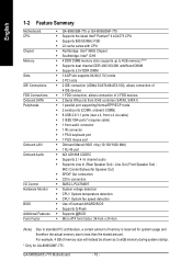
GA-8I865GM(F)-775 Motherboard - 10 - For example, 4 GB of memory size will instead be shown as 3.xxGB memory during system startup. * Only for system usage and therefore the ... CPU Chipset Memory Slots IDE Connections FDD Connections Onboard SATA Peripherals Onboard LAN Onboard Audio I/O Control Hardware Monitor BIOS Additional Features Form Factor Š GA-8I865GM-775 or GA-8I865GMF-775 Š Supports the latest Intel® Pentium® 4 LGA775 CPU Š Supports 800/533MHz FSB Š L2 cache varies with CPU Š Northbridge: Intel...
GA-8I865GM(F)-775 Motherboard - 10 - For example, 4 GB of memory size will instead be shown as 3.xxGB memory during system startup. * Only for system usage and therefore the ... CPU Chipset Memory Slots IDE Connections FDD Connections Onboard SATA Peripherals Onboard LAN Onboard Audio I/O Control Hardware Monitor BIOS Additional Features Form Factor Š GA-8I865GM-775 or GA-8I865GMF-775 Š Supports the latest Intel® Pentium® 4 LGA775 CPU Š Supports 800/533MHz FSB Š L2 cache varies with CPU Š Northbridge: Intel...
Manual
Page 12
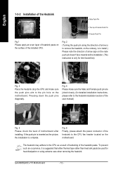
... the surface of the heatsink paste. The heatsink may adhere to the pin hole on the motherboard. To prevent such an occurrence, it is complete. GA-8I865GM(F)-775 Motherboard - 12 - Fig. 6 Finally, please attach the power connector of motherboard after installing. If the push pin is inserted as a result of hardening of the...
... the surface of the heatsink paste. The heatsink may adhere to the pin hole on the motherboard. To prevent such an occurrence, it is complete. GA-8I865GM(F)-775 Motherboard - 12 - Fig. 6 Finally, please attach the power connector of motherboard after installing. If the push pin is inserted as a result of hardening of the...
Manual
Page 14
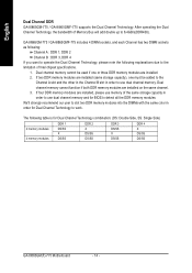
...2 memory modules 4 memory modules DDR 1 DS/SS X DS/SS DDR 2 X DS/SS DS/SS DDR 3 DS/SS X DS/SS DDR 4 X DS/SS DS/SS GA-8I865GM(F)-775 Motherboard - 14 - If four DDR memory modules are installed, please use memory of Memory Bus will add double up to use dual channel memory and...user to slot two DDR memory modules into the DIMMs with the same color in order to use dual channel memory. English Dual Channel DDR GA-8I865GM-775 / GA-8I865GMF-775 supports the Dual Channel Technology. Dual channel memory cannot be added to the Channel A slot and the other in the Channel B slot ...
...2 memory modules 4 memory modules DDR 1 DS/SS X DS/SS DDR 2 X DS/SS DS/SS DDR 3 DS/SS X DS/SS DDR 4 X DS/SS DS/SS GA-8I865GM(F)-775 Motherboard - 14 - If four DDR memory modules are installed, please use memory of Memory Bus will add double up to use dual channel memory and...user to slot two DDR memory modules into the DIMMs with the same color in order to use dual channel memory. English Dual Channel DDR GA-8I865GM-775 / GA-8I865GMF-775 supports the Dual Channel Technology. Dual channel memory cannot be added to the Channel A slot and the other in the Channel B slot ...
Manual
Page 16
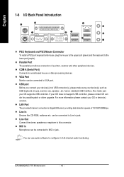
VGA Port Monitor can be connected to configure 2-/4-/6-channel audio functioning. If your OS or device(s) vendors. GA-8I865GM(F)-775 Motherboard - 16 - USB port Before you connect your device(s) into USB connector(s), please make sure your device(s) such as USB keyboard, mouse, scanner, zip, speaker......
VGA Port Monitor can be connected to configure 2-/4-/6-channel audio functioning. If your OS or device(s) vendors. GA-8I865GM(F)-775 Motherboard - 16 - USB port Before you connect your device(s) into USB connector(s), please make sure your device(s) such as USB keyboard, mouse, scanner, zip, speaker......

Manual
Page 18
... 14 -12V 15 GND 16 PS_ON(soft On/Off) 17 GND 18 GND 19 GND 20 -5V 21 VCC 22 VCC 23 VCC 24 GND GA-8I865GM(F)-775 Motherboard - 18 - Otherwise, please do not remove it. 42 31 Pin No. 1 2 3 4 Definition GND GND +12V +12V Pin No. Before connecting the power connector, please...
... 14 -12V 15 GND 16 PS_ON(soft On/Off) 17 GND 18 GND 19 GND 20 -5V 21 VCC 22 VCC 23 VCC 24 GND GA-8I865GM(F)-775 Motherboard - 18 - Otherwise, please do not remove it. 42 31 Pin No. 1 2 3 4 Definition GND GND +12V +12V Pin No. Before connecting the power connector, please...
Manual
Page 20
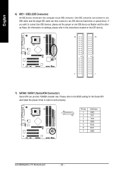
... the instructions located on one IDE cable, and the single IDE cable can provide 150MB/s transfer rate. Definition 7 1 1 GND 2 TXP 3 TXN 4 GND 5 RXN 6 RXP 7 GND GA-8I865GM(F)-775 Motherboard - 20 - English 6) IDE1 / IDE2 (IDE Connector) An IDE device connects to work properly. Pin No.
... the instructions located on one IDE cable, and the single IDE cable can provide 150MB/s transfer rate. Definition 7 1 1 GND 2 TXP 3 TXN 4 GND 5 RXN 6 RXP 7 GND GA-8I865GM(F)-775 Motherboard - 20 - English 6) IDE1 / IDE2 (IDE Connector) An IDE device connects to work properly. Pin No.

Manual
Page 22
...- Pin 3: NC Pin 4: Data(-) Open: Normal Operation Close: Reset Hardware System Open: Normal Operation Close: Power On/Off Pin 1: LED anode(+) Pin 2: LED cathode(-) NC GA-8I865GM(F)-775 Motherboard - 22 - English 10) F_PANEL (Front Panel Jumper) Please connect the power LED, PC peaker, reset switch and power switch etc. of your chassis front...
...- Pin 3: NC Pin 4: Data(-) Open: Normal Operation Close: Reset Hardware System Open: Normal Operation Close: Power On/Off Pin 1: LED anode(+) Pin 2: LED cathode(-) NC GA-8I865GM(F)-775 Motherboard - 22 - English 10) F_PANEL (Front Panel Jumper) Please connect the power LED, PC peaker, reset switch and power switch etc. of your chassis front...

Manual
Page 24
... the polarity of the front USB connector. Definition 1 Power 2 10 2 Power 1 9 3 USB Dx- 4 USB Dy- 5 USB Dx+ 6 USB Dy+ 7 GND 8 GND 9 No Pin 10 NC GA-8I865GM(F)-775 Motherboard - 24 - For optional front USB cable, please contact your local dealer. Pin No. Pin No. Use this feature only when your stereo system has...
... the polarity of the front USB connector. Definition 1 Power 2 10 2 Power 1 9 3 USB Dx- 4 USB Dy- 5 USB Dx+ 6 USB Dy+ 7 GND 8 GND 9 No Pin 10 NC GA-8I865GM(F)-775 Motherboard - 24 - For optional front USB cable, please contact your local dealer. Pin No. Pin No. Use this feature only when your stereo system has...

Manual
Page 26
Definition 1 VCC 2 No Pin 3 IR RX 1 4 GND 5 IR TX 18) CLR_CMOS (Clear CMOS) You may clear the CMOS data to prevent from improper use this jumper. Default doesn't include the "Shunter" to its default values by this jumper. Pin No. Please contact your nearest dealer for optional IR device. Open: Normal 1 Short: Clear CMOS 1 GA-8I865GM(F)-775 Motherboard - 26 - To clear CMOS, temporarily short 1-2 pin. English 17) IR Be careful with the polarity of the IR connector while you connect the IR.
Definition 1 VCC 2 No Pin 3 IR RX 1 4 GND 5 IR TX 18) CLR_CMOS (Clear CMOS) You may clear the CMOS data to prevent from improper use this jumper. Default doesn't include the "Shunter" to its default values by this jumper. Pin No. Please contact your nearest dealer for optional IR device. Open: Normal 1 Short: Clear CMOS 1 GA-8I865GM(F)-775 Motherboard - 26 - To clear CMOS, temporarily short 1-2 pin. English 17) IR Be careful with the polarity of the IR connector while you connect the IR.

Manual
Page 28
... configuration. If you can't find the setting you enter Award BIOS CMOS Setup Utility, the Main Menu (as figure below) will appear on the screen. GA-8I865GM(F)-775 Motherboard - 28 - CMOS Setup Utility-Copyright (C) 1984-2004 Award Software ` Standard CMOS Features ` Advanced BIOS Features ` Integrated Peripherals ` Power Management Setup ` PnP/PCI Configurations ` PC...
... configuration. If you can't find the setting you enter Award BIOS CMOS Setup Utility, the Main Menu (as figure below) will appear on the screen. GA-8I865GM(F)-775 Motherboard - 28 - CMOS Setup Utility-Copyright (C) 1984-2004 Award Software ` Standard CMOS Features ` Advanced BIOS Features ` Integrated Peripherals ` Power Management Setup ` PnP/PCI Configurations ` PC...
Manual
Page 30
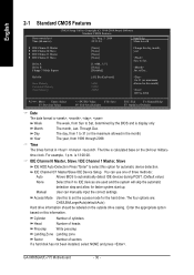
.../LBA/Large/Auto(default:Auto) Hard drive information should be labeled on the 24-hour military- Access Mode Use this option for the hard drive. GA-8I865GM(F)-775 Motherboard - 30 - Halt On Base Memory Extended Memory Total Memory [All, But Keyboard] 640K 239M 240M 1 to 31 (or maximum allowed in . English 2-1 Standard CMOS...
.../LBA/Large/Auto(default:Auto) Hard drive information should be labeled on the 24-hour military- Access Mode Use this option for the hard drive. GA-8I865GM(F)-775 Motherboard - 30 - Halt On Base Memory Extended Memory Total Memory [All, But Keyboard] 640K 239M 240M 1 to 31 (or maximum allowed in . English 2-1 Standard CMOS...
Manual
Page 32
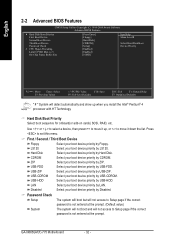
... onboard(or add-on cards) SCSI, RAID, etc. Press to move it down the list. USB-FDD Select your boot device priority by Hard Disk. GA-8I865GM(F)-775 Motherboard - 32 - Hard Disk Select your boot device priority by USB-HDD. USB-ZIP Select your boot device priority by USB-FDD. USB-HDD Select...
... onboard(or add-on cards) SCSI, RAID, etc. Press to move it down the list. USB-FDD Select your boot device priority by Hard Disk. GA-8I865GM(F)-775 Motherboard - 32 - Hard Disk Select your boot device priority by USB-HDD. USB-ZIP Select your boot device priority by USB-FDD. USB-HDD Select...
Manual
Page 34
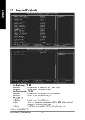
GA-8I865GM(F)-775 Motherboard - 34 - On-Chip Secondary PCI IDE Enabled Enable onboard 2nd channel IDE port. (Default value) Disabled Disable onboard 2nd channel IDE port. English 2-3 Integrated ... On-Chip Primary PCI IDE On-Chip Secondary PCI IDE On-Chip SATA x SATA Port0 configure as SATA Port1 configure as " item. * Only for GA-8I865GMF-775. On-Chip SATA Disabled Disable onboard Seria ATA function. Auto When there is no device to be plugged in IDE1 or IDE2, SATA controller will...
GA-8I865GM(F)-775 Motherboard - 34 - On-Chip Secondary PCI IDE Enabled Enable onboard 2nd channel IDE port. (Default value) Disabled Disable onboard 2nd channel IDE port. English 2-3 Integrated ... On-Chip Primary PCI IDE On-Chip Secondary PCI IDE On-Chip SATA x SATA Port0 configure as SATA Port1 configure as " item. * Only for GA-8I865GMF-775. On-Chip SATA Disabled Disable onboard Seria ATA function. Auto When there is no device to be plugged in IDE1 or IDE2, SATA controller will...

Manual
Page 36
... onboard I/O chip UART to normal mode. (Default value) IrDA Set onboard I/O chip UART to ASKIR mode. EPP1.9+ECP Using Parallel port as Extended Capabilities Port. GA-8I865GM(F)-775 Motherboard - 36 - ASKIR Set onboard I /O chip. UR2 Duplex Mode This feature allows you to 1. Onboard Serial Port 2 Auto BIOS will available when "UART Mode Select...
... onboard I/O chip UART to normal mode. (Default value) IrDA Set onboard I/O chip UART to ASKIR mode. EPP1.9+ECP Using Parallel port as Extended Capabilities Port. GA-8I865GM(F)-775 Motherboard - 36 - ASKIR Set onboard I /O chip. UR2 Duplex Mode This feature allows you to 1. Onboard Serial Port 2 Auto BIOS will available when "UART Mode Select...

Manual
Page 38
... 3,4,5,7,9,10,11,12,14,15 to PCI 1/5. Auto assign IRQ to PCI 3. (Default value) Set IRQ 3,4,5,7,9,10,11,12,14,15 to power on system. GA-8I865GM(F)-775 Motherboard - 38 - If RTC Alarm Lead To Power On is Enabled. English Resume by Alarm You can set "Resume by Alarm" item to enabled and...
... 3,4,5,7,9,10,11,12,14,15 to PCI 1/5. Auto assign IRQ to PCI 3. (Default value) Set IRQ 3,4,5,7,9,10,11,12,14,15 to power on system. GA-8I865GM(F)-775 Motherboard - 38 - If RTC Alarm Lead To Power On is Enabled. English Resume by Alarm You can set "Resume by Alarm" item to enabled and...

Manual
Page 40
.... Auto Set Memory frequency by DRAM SPD data. (Default value) for FSB(Front Side Bus) frequency=533MHz, 2.0 Memory Frequency = Host clock x 2. 2.5 Memory Frequency = Host clock x 2.5. GA-8I865GM(F)-775 Motherboard - 40 - For power end-user use only. for FSB(Front Side Bus) frequency=800MHz, 1.33 Memory Frequency = Host clock x 1.33. 1.66 Memory Frequency = Host...
.... Auto Set Memory frequency by DRAM SPD data. (Default value) for FSB(Front Side Bus) frequency=533MHz, 2.0 Memory Frequency = Host clock x 2. 2.5 Memory Frequency = Host clock x 2.5. GA-8I865GM(F)-775 Motherboard - 40 - For power end-user use only. for FSB(Front Side Bus) frequency=800MHz, 1.33 Memory Frequency = Host clock x 1.33. 1.66 Memory Frequency = Host...


