Manual
Page 1
GA-8I865GM-775 / GA-8I865GMF-775 Intel® Pentium® 4 LGA775 Processor Motherboard User's Manual Rev. 1001 12ME-8I865GMT-1001
GA-8I865GM-775 / GA-8I865GMF-775 Intel® Pentium® 4 LGA775 Processor Motherboard User's Manual Rev. 1001 12ME-8I865GMT-1001
Manual
Page 2
Motherboard GA-8I865GM-775 / GA-8I865GMF-775 Sep. 5, 2004 Motherboard GA-8I865GM-775 / GA-8I865GMF-775 Sep. 5, 2004
Motherboard GA-8I865GM-775 / GA-8I865GMF-775 Sep. 5, 2004 Motherboard GA-8I865GM-775 / GA-8I865GMF-775 Sep. 5, 2004
Manual
Page 4
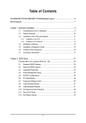
Table of Contents GA-8I865GM-775/GA-8I865GMF-775 Motherboard Layout 6 Block Diagram ...7 Chapter 1 Hardware Installation 9 1-1 Considerations Prior to Installation 9 1-2 Feature Summary 10 1-3 Installation of the CPU and Heatsink 11 1-3-1 Installation of the CPU ...
Table of Contents GA-8I865GM-775/GA-8I865GMF-775 Motherboard Layout 6 Block Diagram ...7 Chapter 1 Hardware Installation 9 1-1 Considerations Prior to Installation 9 1-2 Feature Summary 10 1-3 Installation of the CPU and Heatsink 11 1-3-1 Installation of the CPU ...
Manual
Page 6
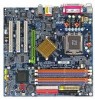
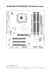
IDE1 GA-8I865GM-775/GA-8I865GMF-775 Motherboard Layout KB_MS ATX_12V LGA775 CPU_FAN ATX FDD COMA GA-8I865GM-775 (or GA-8I865GMF-775*) DDR1 DDR2 DDR3 DDR4 IDE2 LPT VGA R_USB USB LAN F_AUDIO LPC47M997 IR AUDIO BIOS SPDIF Marvell 8001 CODEC CD_IN AGP COMB Intel 865G BAT PCI1 PCI2 TSB43AB23* PCI3 F2_1394* F1_1394* Intel ICH5 SATA1 SATA0 F_USB1 F_USB2 PWR_LED F_PANEL CLR_CMOS SYS_FAN * Only for GA-8I865GMF-775. - 6 -
IDE1 GA-8I865GM-775/GA-8I865GMF-775 Motherboard Layout KB_MS ATX_12V LGA775 CPU_FAN ATX FDD COMA GA-8I865GM-775 (or GA-8I865GMF-775*) DDR1 DDR2 DDR3 DDR4 IDE2 LPT VGA R_USB USB LAN F_AUDIO LPC47M997 IR AUDIO BIOS SPDIF Marvell 8001 CODEC CD_IN AGP COMB Intel 865G BAT PCI1 PCI2 TSB43AB23* PCI3 F2_1394* F1_1394* Intel ICH5 SATA1 SATA0 F_USB1 F_USB2 PWR_LED F_PANEL CLR_CMOS SYS_FAN * Only for GA-8I865GMF-775. - 6 -
Manual
Page 10
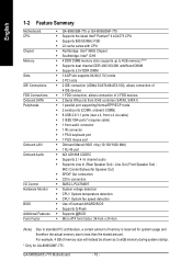
GA-8I865GM(F)-775 Motherboard - 10 - MIC (Center/Subwoofer Speaker Out) Š SPDIF Out connection Š CD In connection Š SMSC LPC47M997 Š System voltage detection Š CPU / System ... CPU Chipset Memory Slots IDE Connections FDD Connections Onboard SATA Peripherals Onboard LAN Onboard Audio I/O Control Hardware Monitor BIOS Additional Features Form Factor Š GA-8I865GM-775 or GA-8I865GMF-775 Š Supports the latest Intel® Pentium® 4 LGA775 CPU Š Supports 800/533MHz FSB Š L2 cache varies with CPU Š Northbridge: Intel...
GA-8I865GM(F)-775 Motherboard - 10 - MIC (Center/Subwoofer Speaker Out) Š SPDIF Out connection Š CD In connection Š SMSC LPC47M997 Š System voltage detection Š CPU / System ... CPU Chipset Memory Slots IDE Connections FDD Connections Onboard SATA Peripherals Onboard LAN Onboard Audio I/O Control Hardware Monitor BIOS Additional Features Form Factor Š GA-8I865GM-775 or GA-8I865GMF-775 Š Supports the latest Intel® Pentium® 4 LGA775 CPU Š Supports 800/533MHz FSB Š L2 cache varies with CPU Š Northbridge: Intel...
Manual
Page 12
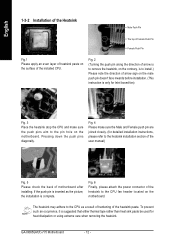
... installation is suggested that either thermal tape rather than heat sink paste be used for heat dissipation or using extreme care when removing the heatsink. GA-8I865GM(F)-775 Motherboard - 12 - Fig. 4 Please make sure the push pins aim to the pin hole on the motherboard. Fig. 6 Finally, please attach the power connector of...
... installation is suggested that either thermal tape rather than heat sink paste be used for heat dissipation or using extreme care when removing the heatsink. GA-8I865GM(F)-775 Motherboard - 12 - Fig. 4 Please make sure the push pins aim to the pin hole on the motherboard. Fig. 6 Finally, please attach the power connector of...
Manual
Page 14
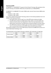
...) 2 memory modules 4 memory modules DDR 1 DS/SS X DS/SS DDR 2 X DS/SS DS/SS DDR 3 DS/SS X DS/SS DDR 4 X DS/SS DS/SS GA-8I865GM(F)-775 Motherboard - 14 - GA-8I865GM-775 / GA-8I865GMF-775 includes 4 DIMM sockets, and each Channel has two DIMM sockets as following: Channel A : DDR 1, DDR 2 Channel B : DDR 3, DDR 4 If you want to operate... Dual Channel Technology, the bandwidth of Intel chipset specifications. 1. Dual channel memory cannot function if both DDR memory modules are installed. 2. English Dual Channel DDR GA-8I865GM-775 / GA-8I865GMF-775 supports the Dual Channel Technology.
...) 2 memory modules 4 memory modules DDR 1 DS/SS X DS/SS DDR 2 X DS/SS DS/SS DDR 3 DS/SS X DS/SS DDR 4 X DS/SS DS/SS GA-8I865GM(F)-775 Motherboard - 14 - GA-8I865GM-775 / GA-8I865GMF-775 includes 4 DIMM sockets, and each Channel has two DIMM sockets as following: Channel A : DDR 1, DDR 2 Channel B : DDR 3, DDR 4 If you want to operate... Dual Channel Technology, the bandwidth of Intel chipset specifications. 1. Dual channel memory cannot function if both DDR memory modules are installed. 2. English Dual Channel DDR GA-8I865GM-775 / GA-8I865GMF-775 supports the Dual Channel Technology.
Manual
Page 16
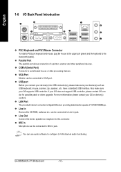
VGA Port Monitor can be connected to configure 2-/4-/6-channel audio functioning. have a standard USB interface. can be connected to Line In jack. GA-8I865GM(F)-775 Motherboard - 16 - Line In Devices like CD-ROM, walkman etc. MIC In Microphone can use audio software to VGA port. USB port Before you connect ...
VGA Port Monitor can be connected to configure 2-/4-/6-channel audio functioning. have a standard USB interface. can be connected to Line In jack. GA-8I865GM(F)-775 Motherboard - 16 - Line In Devices like CD-ROM, walkman etc. MIC In Microphone can use audio software to VGA port. USB port Before you connect ...

Manual
Page 18
... 14 -12V 15 GND 16 PS_ON(soft On/Off) 17 GND 18 GND 19 GND 20 -5V 21 VCC 22 VCC 23 VCC 24 GND GA-8I865GM(F)-775 Motherboard - 18 - Caution! Before connecting the power connector, please make sure that is 24 pins; It is recommended that a power supply that is not connected...
... 14 -12V 15 GND 16 PS_ON(soft On/Off) 17 GND 18 GND 19 GND 20 -5V 21 VCC 22 VCC 23 VCC 24 GND GA-8I865GM(F)-775 Motherboard - 18 - Caution! Before connecting the power connector, please make sure that is 24 pins; It is recommended that a power supply that is not connected...
Manual
Page 20
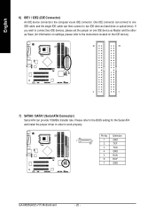
Definition 7 1 1 GND 2 TXP 3 TXN 4 GND 5 RXN 6 RXP 7 GND GA-8I865GM(F)-775 Motherboard - 20 - Please refer to the BIOS setting for information on one IDE cable, and the single IDE cable can provide 150MB/s transfer rate. Pin ...
Definition 7 1 1 GND 2 TXP 3 TXN 4 GND 5 RXN 6 RXP 7 GND GA-8I865GM(F)-775 Motherboard - 20 - Please refer to the BIOS setting for information on one IDE cable, and the single IDE cable can provide 150MB/s transfer rate. Pin ...

Manual
Page 22
.... Pin 3: NC Pin 4: Data(-) Open: Normal Operation Close: Reset Hardware System Open: Normal Operation Close: Power On/Off Pin 1: LED anode(+) Pin 2: LED cathode(-) NC GA-8I865GM(F)-775 Motherboard - 22 - PW+ PWSPEAK+ SPEAK- 2 20 1 19 HD+ HD-
.... Pin 3: NC Pin 4: Data(-) Open: Normal Operation Close: Reset Hardware System Open: Normal Operation Close: Power On/Off Pin 1: LED anode(+) Pin 2: LED cathode(-) NC GA-8I865GM(F)-775 Motherboard - 22 - PW+ PWSPEAK+ SPEAK- 2 20 1 19 HD+ HD-

Manual
Page 24
... SPDIF cable, please contact your local dealer. Definition 1 Power 2 10 2 Power 1 9 3 USB Dx- 4 USB Dy- 5 USB Dx+ 6 USB Dy+ 7 GND 8 GND 9 No Pin 10 NC GA-8I865GM(F)-775 Motherboard - 24 - Use this feature only when your stereo system has digital input function. Check the pin assignment carefully while you connect the SPDIF cable...
... SPDIF cable, please contact your local dealer. Definition 1 Power 2 10 2 Power 1 9 3 USB Dx- 4 USB Dy- 5 USB Dx+ 6 USB Dy+ 7 GND 8 GND 9 No Pin 10 NC GA-8I865GM(F)-775 Motherboard - 24 - Use this feature only when your stereo system has digital input function. Check the pin assignment carefully while you connect the SPDIF cable...

Manual
Page 26
Pin No. To clear CMOS, temporarily short 1-2 pin. Open: Normal 1 Short: Clear CMOS 1 GA-8I865GM(F)-775 Motherboard - 26 - Definition 1 VCC 2 No Pin 3 IR RX 1 4 GND 5 IR TX 18) CLR_CMOS (Clear CMOS) You may clear the CMOS data to prevent from improper use this jumper. English 17) IR Be careful with the polarity of the IR connector while you connect the IR. Please contact your nearest dealer for optional IR device. Default doesn't include the "Shunter" to its default values by this jumper.
Pin No. To clear CMOS, temporarily short 1-2 pin. Open: Normal 1 Short: Clear CMOS 1 GA-8I865GM(F)-775 Motherboard - 26 - Definition 1 VCC 2 No Pin 3 IR RX 1 4 GND 5 IR TX 18) CLR_CMOS (Clear CMOS) You may clear the CMOS data to prevent from improper use this jumper. English 17) IR Be careful with the polarity of the IR connector while you connect the IR. Please contact your nearest dealer for optional IR device. Default doesn't include the "Shunter" to its default values by this jumper.

Manual
Page 28
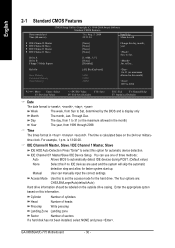
GA-8I865GM(F)-775 Motherboard - 28 - Use arrow keys to select among the items and press to search the advanced option hidden. „ Standard CMOS Features This setup page ...
GA-8I865GM(F)-775 Motherboard - 28 - Use arrow keys to select among the items and press to search the advanced option hidden. „ Standard CMOS Features This setup page ...
Manual
Page 30
... to Sat. For example, 1 p.m. The four options are used and the system will skip the automatic detection step and allow for faster system start up. GA-8I865GM(F)-775 Motherboard - 30 - to Sat, determined by the BIOS and is , , , . Through Dec. IDE Channel 0 Master, Slave / IDE Channel 1 Master, Slave IDE HDD Auto-Detection Press...
... to Sat. For example, 1 p.m. The four options are used and the system will skip the automatic detection step and allow for faster system start up. GA-8I865GM(F)-775 Motherboard - 30 - to Sat, determined by the BIOS and is , , , . Through Dec. IDE Channel 0 Master, Slave / IDE Channel 1 Master, Slave IDE HDD Auto-Detection Press...
Manual
Page 32
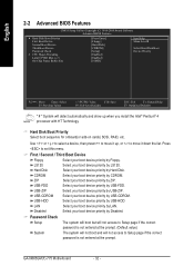
..., RAID, etc. First / Second / Third Boot Device Floppy Select your boot device priority by LS120. USB-CDROM Select your boot device priority by USB-HDD. GA-8I865GM(F)-775 Motherboard - 32 - USB-HDD Select your boot device priority by Floppy. to 3 On-Chip Frame Buffer Size [Press Enter] [Floppy] [Hard Disk] [CDROM] [Setup] [Enabled...
..., RAID, etc. First / Second / Third Boot Device Floppy Select your boot device priority by LS120. USB-CDROM Select your boot device priority by USB-HDD. GA-8I865GM(F)-775 Motherboard - 32 - USB-HDD Select your boot device priority by Floppy. to 3 On-Chip Frame Buffer Size [Press Enter] [Floppy] [Hard Disk] [CDROM] [Setup] [Enabled...
Manual
Page 34
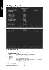
GA-8I865GM(F)-775 Motherboard - 34 - English 2-3 Integrated Peripherals CMOS Setup Utility-Copyright (C) 1984-2004 Award Software Integrated Peripherals On-Chip Primary PCI IDE On-Chip Secondary PCI IDE On-Chip SATA x SATA Port0 configure as SATA Port1 configure as " item. * Only for GA-8I865GMF-775. On-Chip SATA Disabled Disable onboard Seria ATA function. Auto When...
GA-8I865GM(F)-775 Motherboard - 34 - English 2-3 Integrated Peripherals CMOS Setup Utility-Copyright (C) 1984-2004 Award Software Integrated Peripherals On-Chip Primary PCI IDE On-Chip Secondary PCI IDE On-Chip SATA x SATA Port0 configure as SATA Port1 configure as " item. * Only for GA-8I865GMF-775. On-Chip SATA Disabled Disable onboard Seria ATA function. Auto When...

Manual
Page 36
... UART to normal mode. (Default value) IrDA Set onboard I/O chip UART to ASKIR mode. ECP Using Parallel port as Enhanced Parallel Port 1.9 and SPP mode. GA-8I865GM(F)-775 Motherboard - 36 - ASKIR Set onboard I /O chip. Half IR Function Duplex Half. (Default value) Full IR Function Duplex Full. EPP1.9+SPP Using Parallel port as Extended...
... UART to normal mode. (Default value) IrDA Set onboard I/O chip UART to ASKIR mode. ECP Using Parallel port as Enhanced Parallel Port 1.9 and SPP mode. GA-8I865GM(F)-775 Motherboard - 36 - ASKIR Set onboard I /O chip. Half IR Function Duplex Half. (Default value) Full IR Function Duplex Full. EPP1.9+SPP Using Parallel port as Extended...

Manual
Page 38
Auto assign IRQ to PCI 2. (Default value) Set IRQ 3,4,5,7,9,10,11,12,14,15 to PCI 1/5. GA-8I865GM(F)-775 Motherboard - 38 - Date (of Month) Alarm : Everyday, 1~31 Time (hh: mm: ss) Alarm : (0~23) : (0~59) : (0~59) 2-5 PnP/PCI Configurations CMOS Setup Utility-Copyright (C) 1984-2004 ...
Auto assign IRQ to PCI 2. (Default value) Set IRQ 3,4,5,7,9,10,11,12,14,15 to PCI 1/5. GA-8I865GM(F)-775 Motherboard - 38 - Date (of Month) Alarm : Everyday, 1~31 Time (hh: mm: ss) Alarm : (0~23) : (0~59) : (0~59) 2-5 PnP/PCI Configurations CMOS Setup Utility-Copyright (C) 1984-2004 ...

Manual
Page 40
... CPU detection. for FSB(Front Side Bus) frequency=800MHz, 1.33 Memory Frequency = Host clock x 1.33. 1.66 Memory Frequency = Host clock x 1.66. 2.0 Memory Frequency = Host clock x 2. GA-8I865GM(F)-775 Motherboard - 40 - English 2-7 Frequency/Voltage Control CMOS Setup Utility-Copyright (C) 1984-2004 Award Software Frequency/Voltage Control CPU Clock Ratio Memory Frequency For Memory Frequency...
... CPU detection. for FSB(Front Side Bus) frequency=800MHz, 1.33 Memory Frequency = Host clock x 1.33. 1.66 Memory Frequency = Host clock x 1.66. 2.0 Memory Frequency = Host clock x 2. GA-8I865GM(F)-775 Motherboard - 40 - English 2-7 Frequency/Voltage Control CMOS Setup Utility-Copyright (C) 1984-2004 Award Software Frequency/Voltage Control CPU Clock Ratio Memory Frequency For Memory Frequency...


