
Manual
Page 5
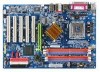
Table of Contents ItemChecklist ...7 OptionalAccessories ...7 GA-8I865G775-G(-RH) Motherboard Layout 8 Block Diagram ...9 Chapter 1 Hardware Installation 11 1-1 Considerations Prior to Installation 11 1-2 Feature Summary 12 1-3 Installation of the CPU and Heatsink 14 1-3-1 Installation of the CPU 14 1-3-2 Installation of the Heatsink 15 1-4 Installation of Memory 16 1-5 Installation of Expansion Cards 17 1-6 I/O Back Panel Introduction 18 1-7 Connectors...
Table of Contents ItemChecklist ...7 OptionalAccessories ...7 GA-8I865G775-G(-RH) Motherboard Layout 8 Block Diagram ...9 Chapter 1 Hardware Installation 11 1-1 Considerations Prior to Installation 11 1-2 Feature Summary 12 1-3 Installation of the CPU and Heatsink 14 1-3-1 Installation of the CPU 14 1-3-2 Installation of the Heatsink 15 1-4 Installation of Memory 16 1-5 Installation of Expansion Cards 17 1-6 I/O Back Panel Introduction 18 1-7 Connectors...

Manual
Page 11
...that the power supply is best to improper installation. 4. Damage due to wear an electrostatic discharge (ESD) cuff when handling electronic components (CPU, RAM). 4. It is switched off the computer and unplug its components. 5. Prior to natural disaster, accident or human cause. 2.... cord. 2. Damage due to installation, please do not place the computer system on the motherboard. Thus, prior to be an unofficial Gigabyte product. - 11 - Prior to the installation of the product, please consult a certified computer technician. Product determined to installation, please ...
...that the power supply is best to improper installation. 4. Damage due to wear an electrostatic discharge (ESD) cuff when handling electronic components (CPU, RAM). 4. It is switched off the computer and unplug its components. 5. Prior to natural disaster, accident or human cause. 2.... cord. 2. Damage due to installation, please do not place the computer system on the motherboard. Thus, prior to be an unofficial Gigabyte product. - 11 - Prior to the installation of the product, please consult a certified computer technician. Product determined to installation, please ...

Manual
Page 12
...; Supports LGA775 Intel® Processor Pentium® 4(Note 1) Š L2 cache varies with CPU Front Side Bus Š Supports 800/533MHz FSB Chipset Š Northbridge:Intel® 865G Š Southbridge: Intel® ... CPU fan connector Š 1 system fan connector Š 1 front panel connector Š 1 front audio connector Š 1 COMB connector Š 1 CD In connector Š 1 AUX In connector Š 1 Surround Center connector Š 1 SPDIF Out connector Š 1 power LED connector Š 2 USB 2.0/1.1 connectors for additional 4 ports by cables GA-8I865G775-G(-RH...
...; Supports LGA775 Intel® Processor Pentium® 4(Note 1) Š L2 cache varies with CPU Front Side Bus Š Supports 800/533MHz FSB Chipset Š Northbridge:Intel® 865G Š Southbridge: Intel® ... CPU fan connector Š 1 system fan connector Š 1 front panel connector Š 1 front audio connector Š 1 COMB connector Š 1 CD In connector Š 1 AUX In connector Š 1 Surround Center connector Š 1 SPDIF Out connector Š 1 power LED connector Š 2 USB 2.0/1.1 connectors for additional 4 ports by cables GA-8I865G775-G(-RH...

Manual
Page 13
...) I/O Control Š IT8712 chip Hardware Monitor Š System voltage detection Š CPU temperature detection Š CPU / System fan speed detection Š CPU warning temperature Š CPU System fan failure warning Š CPU smart fan control BIOS Š 1 4Mbit flash ROM Š Use of licensed AWARD...Norton Internet Security (OEM version) Form Factor Š ATX form factor; 30.5cm x 21cm (Note 1) For further CPU support information, please go to GIGABYTE's website. (Note 2) Due to standard PC architecture, a certain amount of memory size will instead be shown as 3.xxGB...
...) I/O Control Š IT8712 chip Hardware Monitor Š System voltage detection Š CPU temperature detection Š CPU / System fan speed detection Š CPU warning temperature Š CPU System fan failure warning Š CPU smart fan control BIOS Š 1 4Mbit flash ROM Š Use of licensed AWARD...Norton Internet Security (OEM version) Form Factor Š ATX form factor; 30.5cm x 21cm (Note 1) For further CPU support information, please go to GIGABYTE's website. (Note 2) Due to standard PC architecture, a certain amount of memory size will instead be shown as 3.xxGB...
Manual
Page 14
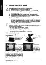
... with the triangle and gently insert the CPU into position. (Grasping the CPU firmly between the CPU and heatsink. 4. Chipset: An Intel® Chipset that the motherboard supports the CPU. 2. Fig. 2 Remove the plastic covering on the CPU socket to the CPU during installation.) GA-8I865G775-G(-RH) Motherboard - 14 - Fig. 4 Once the CPU is not recommended that might cause...
... with the triangle and gently insert the CPU into position. (Grasping the CPU firmly between the CPU and heatsink. 4. Chipset: An Intel® Chipset that the motherboard supports the CPU. 2. Fig. 2 Remove the plastic covering on the CPU socket to the CPU during installation.) GA-8I865G775-G(-RH) Motherboard - 14 - Fig. 4 Once the CPU is not recommended that might cause...

Manual
Page 15
...sign on the male push pin doesn't face inwards before installation. (This instruction is only for Intel boxed fan) Fig. 3 Place the heatsink atop the CPU and make sure the Male and Female push pin are joined closely. (for detailed installation instructions, please refer to the... heatsink, on the contrary, is to install.) Please note the direction of motherboard after installing. Fig. 4 Please make sure the push pins aim to the CPU fan header located on the motherboard. English 1-3-2 Installation of the Heatsink Male Push Pin The top of Female Push Pin Female Push Pin Fig.1 Please...
...sign on the male push pin doesn't face inwards before installation. (This instruction is only for Intel boxed fan) Fig. 3 Place the heatsink atop the CPU and make sure the Male and Female push pin are joined closely. (for detailed installation instructions, please refer to the... heatsink, on the contrary, is to install.) Please note the direction of motherboard after installing. Fig. 4 Please make sure the push pins aim to the CPU fan header located on the motherboard. English 1-3-2 Installation of the Heatsink Male Push Pin The top of Female Push Pin Female Push Pin Fig.1 Please...

Manual
Page 20
... unable to start . Align the power connector with its proper location on /off) 15 GND 16 GND 17 GND 18 -5V 19 +5V 20 +5V GA-8I865G775-G(-RH) Motherboard - 20 - If you use a power supply that is not connected, the system will not start . Definition 10 20 1 3.3V 2 3.3V 3 GND 4 +5V ... 11 11 3.3V 12 -12V 13 GND 14 PS_ON(soft on the motherboard and connect tightly. The ATX_12V power connector mainly supplies power to the CPU. Please use a 24-pin ATX power supply, please remove the small cover on the power connector on the motherboard. If a power supply is ...
... unable to start . Align the power connector with its proper location on /off) 15 GND 16 GND 17 GND 18 -5V 19 +5V 20 +5V GA-8I865G775-G(-RH) Motherboard - 20 - If you use a power supply that is not connected, the system will not start . Definition 10 20 1 3.3V 2 3.3V 3 GND 4 +5V ... 11 11 3.3V 12 -12V 13 GND 14 PS_ON(soft on the motherboard and connect tightly. The ATX_12V power connector mainly supplies power to the CPU. Please use a 24-pin ATX power supply, please remove the small cover on the power connector on the motherboard. If a power supply is ...

Manual
Page 21
... drive or optical drive). A red power connector wire indicates a positive connection and requires a +12V power voltage. Remember to connect the CPU/system fan cable to the CPU_FAN/SYS_FAN connector to prevent CPU damage or system hanging caused by overheating. 1 CPU_FAN 1 SYS_FAN Pin No. 1 2 3 4 Definition GND +12V Sense Speed Control (Only for CPU_FAN...
... drive or optical drive). A red power connector wire indicates a positive connection and requires a +12V power voltage. Remember to connect the CPU/system fan cable to the CPU_FAN/SYS_FAN connector to prevent CPU damage or system hanging caused by overheating. 1 CPU_FAN 1 SYS_FAN Pin No. 1 2 3 4 Definition GND +12V Sense Speed Control (Only for CPU_FAN...

Manual
Page 33
.... „ PC Health Status This setup page is the System auto detect Temperature, voltage, fan, speed. „ MB Intelligent Tweaker(M.I.T.) This setup page is control CPU clock and frequency ratio. „ Load Fail-Safe Defaults Fail-Safe Defaults indicates the value of the system parameters which the system would be in...
.... „ PC Health Status This setup page is the System auto detect Temperature, voltage, fan, speed. „ MB Intelligent Tweaker(M.I.T.) This setup page is control CPU clock and frequency ratio. „ Load Fail-Safe Defaults Fail-Safe Defaults indicates the value of the system parameters which the system would be in...

Manual
Page 35
... Precomp Write precomp Landing Zone Landing zone Sector Number of sectors Drive A / Drive B The category identifies the types of memory located above 1 MB in the CPU's memory address map. Floppy 3 Mode Support (for any error that may be prompted. No Errors The system boot will not stop for Japan Area) Disabled...
... Precomp Write precomp Landing Zone Landing zone Sector Number of sectors Drive A / Drive B The category identifies the types of memory located above 1 MB in the CPU's memory address map. Floppy 3 Mode Support (for any error that may be prompted. No Errors The system boot will not stop for Japan Area) Disabled...

Manual
Page 36
...the list. Use < > or < > to select a device, then press to move it up, or to 3 No-Execute Memory Protect (Note) CPU Enhanced Halt (C1E) (Note) CPU Thermal Monitor 2(TM2) (Note) CPU EIST Function (Note) On-Chip Frame Buffer Size [Press Enter] [Floppy] [Hard Disk] [CDROM] [Setup] [Enabled] [Disabled] [Enabled] [...your boot device priority by ZIP. USB-FDD Select your boot device priority by USB-FDD. LAN Select your boot device priority by LAN. GA-8I865G775-G(-RH) Motherboard - 36 - Hard Disk Boot Priority Select boot sequence for onboard(or add-on cards) SCSI, RAID, etc. USB-HDD...
...the list. Use < > or < > to select a device, then press to move it up, or to 3 No-Execute Memory Protect (Note) CPU Enhanced Halt (C1E) (Note) CPU Thermal Monitor 2(TM2) (Note) CPU EIST Function (Note) On-Chip Frame Buffer Size [Press Enter] [Floppy] [Hard Disk] [CDROM] [Setup] [Enabled] [Disabled] [Enabled] [...your boot device priority by ZIP. USB-FDD Select your boot device priority by USB-FDD. LAN Select your boot device priority by LAN. GA-8I865G775-G(-RH) Motherboard - 36 - Hard Disk Boot Priority Select boot sequence for onboard(or add-on cards) SCSI, RAID, etc. USB-HDD...
Manual
Page 37
...size to 1MB. 4MB 8MB 16MB 32MB Set on -chip frame buffer size to 4MB. English CPU Hyper-Threading Enabled Disabled Enables CPU Hyper Threading Feature. Disabled Disables CPUID Limit for operating system with multi processors mode supported. (Default value) ...Disables CPU Hyper Threading. Please note that this function. - 37 - CPU EIST Function (Note) Enabled Disabled Enable CPU EIST function. (Default value) Disable EIST function. Limit CPUID Max. BIOS Setup CPU Enhanced Halt (C1E) (Note) Enabled Enable CPU Enhanced Halt (C1E) function. ...
...size to 1MB. 4MB 8MB 16MB 32MB Set on -chip frame buffer size to 4MB. English CPU Hyper-Threading Enabled Disabled Enables CPU Hyper Threading Feature. Disabled Disables CPUID Limit for operating system with multi processors mode supported. (Default value) ...Disables CPU Hyper Threading. Please note that this function. - 37 - CPU EIST Function (Note) Enabled Disabled Enable CPU EIST function. (Default value) Disable EIST function. Limit CPUID Max. BIOS Setup CPU Enhanced Halt (C1E) (Note) Enabled Enable CPU Enhanced Halt (C1E) function. ...

Manual
Page 44
..." will show "Yes". If the case have been opened, "Case Opened" will restart. Current CPU/SYSTEM FAN Speed (RPM) Detect CPU/SYSTEM Fan speed status automatically. Monitor CPU temperature at 80oC / 176oF. 90oC / 194oF Disabled Monitor CPU temperature at 70oC / 158oF. GA-8I865G775-G(-RH) Motherboard - 44 - Current Voltage(V) Vcore / DDR25V / +3.3V / +12V Detect system's voltage status...
..." will show "Yes". If the case have been opened, "Case Opened" will restart. Current CPU/SYSTEM FAN Speed (RPM) Detect CPU/SYSTEM Fan speed status automatically. Monitor CPU temperature at 80oC / 176oF. 90oC / 194oF Disabled Monitor CPU temperature at 70oC / 158oF. GA-8I865G775-G(-RH) Motherboard - 44 - Current Voltage(V) Vcore / DDR25V / +3.3V / +12V Detect system's voltage status...

Manual
Page 45
...speed with a 4-pin fan power cable. With such CPU fans, selecting PWM will run at different speed depending on their requirements. (Default Value) CPU Smart FAN Mode This option is available only when CPU Smart FAN Control is enabled, CPU fan will not effectively reduce the fan speed. - ...45 - BIOS Setup However, some 4-pin CPU fan power cables are not designed following Intel 4-...
...speed with a 4-pin fan power cable. With such CPU fans, selecting PWM will run at different speed depending on their requirements. (Default Value) CPU Smart FAN Mode This option is available only when CPU Smart FAN Control is enabled, CPU fan will not effectively reduce the fan speed. - ...45 - BIOS Setup However, some 4-pin CPU fan power cables are not designed following Intel 4-...
Manual
Page 46
... option will show up when you use only. Disabled Disable CPU Host Clock Control. (Default value) Enabled Enable CPU Host Clock Control. Serial ATA device is not changeable. GA-8I865G775-G(-RH) Motherboard - 46 - The option will be available when "CPU Host Clock Control" is set "CPU Host Frequency" to 200MHz. For power End-User use only...
... option will show up when you use only. Disabled Disable CPU Host Clock Control. (Default value) Enabled Enable CPU Host Clock Control. Serial ATA device is not changeable. GA-8I865G775-G(-RH) Motherboard - 46 - The option will be available when "CPU Host Clock Control" is set "CPU Host Frequency" to 200MHz. For power End-User use only...

Manual
Page 47
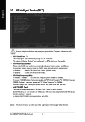
... OverVoltage Control to Normal. (Default value) Set FSB OverVoltage Control to +0.6V. AGP/PCI/SRC Frequency (Mhz) The values depend on "CPU Host Frequency(Mhz)" item. Incorrect using it may damage to +0.3V. For power End-User use only! Set FSB OverVoltage Control to ...1.6000V. (Default value: Normal) Normal CPU Vcore Display your CPU Vcore Voltage. - 47 - CPU Voltage Control Supports adjustable CPU Vcore from 0.8375V to +0.2V. English Memory Frequency For Wrong frequency may occur. Auto Set Memory ...
... OverVoltage Control to Normal. (Default value) Set FSB OverVoltage Control to +0.6V. AGP/PCI/SRC Frequency (Mhz) The values depend on "CPU Host Frequency(Mhz)" item. Incorrect using it may damage to +0.3V. For power End-User use only! Set FSB OverVoltage Control to ...1.6000V. (Default value: Normal) Normal CPU Vcore Display your CPU Vcore Voltage. - 47 - CPU Voltage Control Supports adjustable CPU Vcore from 0.8375V to +0.2V. English Memory Frequency For Wrong frequency may occur. Auto Set Memory ...

Manual
Page 57
... Help button Display EasyTuneTM 5 Help file 11. GO Confirmation and Execution button 6. Display screen Display panel of both CPU cooling fan and North-Bridge Chipset cooling fan, 4) PC health for enhancing system performance, 2) C.I.A. English Chapter 4... and manageability utility. Overclocking Enters the Overclocking setting page 2. "Easy Mode" & "Advance Mode" Toggles between Easy and Advance Mode 7. GIGABYTE Logo Log on different motherboards. - 57 - and M.I .B./2 setting page 3. C.I.A./C.I.A.2 and M.I.B./M.I.B.2 Enters the C.I.A./2 and M.I .B. Appendix ...
... Help button Display EasyTuneTM 5 Help file 11. GO Confirmation and Execution button 6. Display screen Display panel of both CPU cooling fan and North-Bridge Chipset cooling fan, 4) PC health for enhancing system performance, 2) C.I.A. English Chapter 4... and manageability utility. Overclocking Enters the Overclocking setting page 2. "Easy Mode" & "Advance Mode" Toggles between Easy and Advance Mode 7. GIGABYTE Logo Log on different motherboards. - 57 - and M.I .B./2 setting page 3. C.I.A./C.I.A.2 and M.I.B./M.I.B.2 Enters the C.I.A./2 and M.I .B. Appendix ...


