
Manual
Page 3
...page on your motherboard revision before updating motherboard BIOS, drivers, or when looking for technical information. Disclaimer Information in the use GIGABYTE's unique features, read the User's Manual. Changes to use of this product, GIGABYTE provides the following types of documentations: For ... For product-related information, check on our website at: http://www.gigabyte.com Identifying Your Motherboard Revision The revision number on our website. For example, "REV: 1.0" means the revision of GIGABYTE. No part of the product, read the Quick Installation Guide included ...
...page on your motherboard revision before updating motherboard BIOS, drivers, or when looking for technical information. Disclaimer Information in the use GIGABYTE's unique features, read the User's Manual. Changes to use of this product, GIGABYTE provides the following types of documentations: For ... For product-related information, check on our website at: http://www.gigabyte.com Identifying Your Motherboard Revision The revision number on our website. For example, "REV: 1.0" means the revision of GIGABYTE. No part of the product, read the Quick Installation Guide included ...

Manual
Page 4
Table of Contents Box Contents...6 Optional Items...6 GA-880G-UD3H Motherboard Layout 7 GA-880G-UD3H Motherboard Block Diagram 8 Chapter 1 Hardware Installation 9 1-1 Installation Precautions 9 1-2 Product Specifications 10 1-3 Installing the CPU and CPU Cooler...8482; Configuration 19 1-7 Back Panel Connectors 20 1-8 Internal Connectors 23 Chapter 2 BIOS Setup 33 2-1 Startup Screen 34 2-2 The Main Menu 35 2-3 MB Intelligent Tweaker(M.I.T 37 2-4 Standard CMOS Features 44 2-5 Advanced BIOS Features 46 2-6 Integrated Peripherals 48 2-7 Power Management Setup 51 2-8 PnP/PCI ...
Table of Contents Box Contents...6 Optional Items...6 GA-880G-UD3H Motherboard Layout 7 GA-880G-UD3H Motherboard Block Diagram 8 Chapter 1 Hardware Installation 9 1-1 Installation Precautions 9 1-2 Product Specifications 10 1-3 Installing the CPU and CPU Cooler...8482; Configuration 19 1-7 Back Panel Connectors 20 1-8 Internal Connectors 23 Chapter 2 BIOS Setup 33 2-1 Startup Screen 34 2-2 The Main Menu 35 2-3 MB Intelligent Tweaker(M.I.T 37 2-4 Standard CMOS Features 44 2-5 Advanced BIOS Features 46 2-6 Integrated Peripherals 48 2-7 Power Management Setup 51 2-8 PnP/PCI ...
Manual
Page 5
... 60 3-4 Contact...61 3-5 System...61 3-6 Download Center 62 3-7 New Utilities...62 Chapter 4 Unique Features 63 4-1 Xpress Recovery2 63 4-2 BIOS Update Utilities 66 4-2-1 Updating the BIOS with the Q-Flash Utility 66 4-2-2 Updating the BIOS with the @BIOS Utility 69 4-3 EasyTune 6...70 4-4 Easy Energy Saver 71 4-5 Q-Share...73 4-6 SMART Recovery 74 4-7 Auto Green...75 Chapter 5 Appendix...
... 60 3-4 Contact...61 3-5 System...61 3-6 Download Center 62 3-7 New Utilities...62 Chapter 4 Unique Features 63 4-1 Xpress Recovery2 63 4-2 BIOS Update Utilities 66 4-2-1 Updating the BIOS with the Q-Flash Utility 66 4-2-2 Updating the BIOS with the @BIOS Utility 69 4-3 EasyTune 6...70 4-4 Easy Energy Saver 71 4-5 Q-Share...73 4-6 SMART Recovery 74 4-7 Auto Green...75 Chapter 5 Appendix...

Manual
Page 8
... is populated with the PCIEX4_1 slot. The PCIEX1_2 and PCIEX1_3 slots share bandwidth with a x4 card, the PCIEX1_2 and PCIEX1_3 slots become unavailable. - 8 - GA-880G-UD3H Motherboard Block Diagram 1 PCI Express x16 1 PCI Express x4 (Note 3) AM3 CPU CPU CLK+/- (200 MHz) DDR3 1866 (O.C.) (Note 1)/ 1333/1066 MHz...LAN 6 SATA 3Gb/s ATA-133/100/66/33 IDE Channel PCI Bus T.I. TSB43AB23 3 IEEE 1394a AMD 880G D-Sub DVI-D (Note 2) HDMI (Note 2) 12 USB Ports AMD SB710 Dual BIOS CODEC LPC Bus iTE IT8718 Floppy LPT Port COM Port PS/2 KB/Mouse Surround Speaker Out Center/Subwoofer Speaker...
... is populated with the PCIEX4_1 slot. The PCIEX1_2 and PCIEX1_3 slots share bandwidth with a x4 card, the PCIEX1_2 and PCIEX1_3 slots become unavailable. - 8 - GA-880G-UD3H Motherboard Block Diagram 1 PCI Express x16 1 PCI Express x4 (Note 3) AM3 CPU CPU CLK+/- (200 MHz) DDR3 1866 (O.C.) (Note 1)/ 1333/1066 MHz...LAN 6 SATA 3Gb/s ATA-133/100/66/33 IDE Channel PCI Bus T.I. TSB43AB23 3 IEEE 1394a AMD 880G D-Sub DVI-D (Note 2) HDMI (Note 2) 12 USB Ports AMD SB710 Dual BIOS CODEC LPC Bus iTE IT8718 Floppy LPT Port COM Port PS/2 KB/Mouse Surround Speaker Out Center/Subwoofer Speaker...

Manual
Page 12
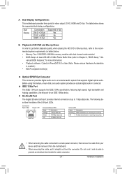
... 4 GB of physical memory is not supported. (Note 5) The PCIEX1_2 and PCIEX1_3 slots share bandwidth with the PCIEX4_1 slot. Hardware Installation - 12 - I/O Controller w Hardware Monitor w w w w w w BIOS w w w w Unique Features w w w w w w w w w w w w Bundled Software w iTE IT8718 chip System voltage detection CPU/System temperature detection CPU/System/Power fan speed detection CPU overheating warning CPU/System...
... 4 GB of physical memory is not supported. (Note 5) The PCIEX1_2 and PCIEX1_3 slots share bandwidth with the PCIEX4_1 slot. Hardware Installation - 12 - I/O Controller w Hardware Monitor w w w w w w BIOS w w w w Unique Features w w w w w w w w w w w w Bundled Software w iTE IT8718 chip System voltage detection CPU/System temperature detection CPU/System/Power fan speed detection CPU overheating warning CPU/System...
Manual
Page 16
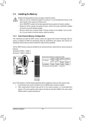
After the memory is recommended that the motherboard supports the memory. Dual Channel mode cannot be used . (Go to GIGABYTE's website for optimum performance. DS/SS DS/SS Four Modules DS/SS DS/SS DS/SS DS/SS (SS=Single-Sided, DS=Double-Sided, "-...; Make sure that memory of the memory. If you begin to prevent hardware damage. • Memory modules have a foolproof design. It is installed, the BIOS will double the original memory bandwidth. 1-4 Installing the Memory Read the following guidelines before you are divided into two channels and each channel has two...
After the memory is recommended that the motherboard supports the memory. Dual Channel mode cannot be used . (Go to GIGABYTE's website for optimum performance. DS/SS DS/SS Four Modules DS/SS DS/SS DS/SS DS/SS (SS=Single-Sided, DS=Double-Sided, "-...; Make sure that memory of the memory. If you begin to prevent hardware damage. • Memory modules have a foolproof design. It is installed, the BIOS will double the original memory bandwidth. 1-4 Installing the Memory Read the following guidelines before you are divided into two channels and each channel has two...

Manual
Page 18
...securely seated in your expansion card. • Always turn off the computer and unplug the power cord from the slot. If necessary, go to BIOS Setup to correctly install your card. Example: Installing and Removing a PCI Express Graphics Card: • Installing a Graphics Card: Gently push down ...Express x1 Slot PCI Express x16 Slot (PCIEX16_1) PCI Express x16 Slot (PCIEX4_1) PCI Slot Follow the steps below to make any required BIOS changes for your computer. After installing all expansion cards, replace the chassis cover(s). 6. Make sure the card is fully inserted into the slot. ...
...securely seated in your expansion card. • Always turn off the computer and unplug the power cord from the slot. If necessary, go to BIOS Setup to correctly install your card. Example: Installing and Removing a PCI Express Graphics Card: • Installing a Graphics Card: Gently push down ...Express x1 Slot PCI Express x16 Slot (PCIEX16_1) PCI Express x16 Slot (PCIEX4_1) PCI Slot Follow the steps below to make any required BIOS changes for your computer. After installing all expansion cards, replace the chassis cover(s). 6. Make sure the card is fully inserted into the slot. ...

Manual
Page 19
...Set UMA Frame Buffer Size to Disabled. - Set Surround View to 256MB or 512MB. (Note 2) - D. Windows 7/Vista operating system - BIOS Setup Enter BIOS Setup to UMA. (Note 2) - C. Set Internal Graphics Mode to set the following instructions on the back panel. Set Init Display First... Card" and install an ATI Hybrid CrossFireX-supported graphics card on the PCI Express slot. Read the following items under the Advanced BIOS Features menu: - An ATI Hybrid CrossFireX-supported motherboard and correct driver - 1-6 Setup of the ATI Hybrid CrossFireX™ Configuration ...
...Set UMA Frame Buffer Size to Disabled. - Set Surround View to 256MB or 512MB. (Note 2) - D. Windows 7/Vista operating system - BIOS Setup Enter BIOS Setup to UMA. (Note 2) - C. Set Internal Graphics Mode to set the following instructions on the back panel. Set Init Display First... Card" and install an ATI Hybrid CrossFireX-supported graphics card on the PCI Express slot. Read the following items under the Advanced BIOS Features menu: - An ATI Hybrid CrossFireX-supported motherboard and correct driver - 1-6 Setup of the ATI Hybrid CrossFireX™ Configuration ...
Manual
Page 21
...ensure that supports digital optical audio. RJ-45 LAN Port The Gigabit Ethernet LAN port provides Internet connection at up to Chapter 2, "BIOS Setup," "Ad- Connection/ Speed LED Activity LED LAN Port Connection/Speed LED: State Description Orange 1 Gbps data rate Green 100 ... cable connector. - 21 - Dual Display Combination DVI-D + D-Sub DVI-D + HDMI HDMI + D-Sub Supported or Not Yes No Yes B. vanced BIOS Features," for more information) • Playback software: CyberLink PowerDVD 8.0 or later (Note: Please ensure Hardware Acceleration is occurring • When removing the ...
...ensure that supports digital optical audio. RJ-45 LAN Port The Gigabit Ethernet LAN port provides Internet connection at up to Chapter 2, "BIOS Setup," "Ad- Connection/ Speed LED Activity LED LAN Port Connection/Speed LED: State Description Orange 1 Gbps data rate Green 100 ... cable connector. - 21 - Dual Display Combination DVI-D + D-Sub DVI-D + HDMI HDMI + D-Sub Supported or Not Yes No Yes B. vanced BIOS Features," for more information) • Playback software: CyberLink PowerDVD 8.0 or later (Note: Please ensure Hardware Acceleration is occurring • When removing the ...

Manual
Page 27
...drive activity LED, speaker and etc. The LED keeps blinking when the sys- When connecting your system using the power switch (refer to Chapter 2, "BIOS Setup," "Power Management Setup," for information about beep codes. • HD (Hard Drive Activity LED, Blue) Connects to the power status indicator on... when the system is detected, the BIOS may configure the way to turn off (S5). • PW (Power Switch, Red): Connects to this header, make sure the wire assignments and...
...drive activity LED, speaker and etc. The LED keeps blinking when the sys- When connecting your system using the power switch (refer to Chapter 2, "BIOS Setup," "Power Management Setup," for information about beep codes. • HD (Hard Drive Activity LED, Blue) Connects to the power status indicator on... when the system is detected, the BIOS may configure the way to turn off (S5). • PW (Power Switch, Red): Connects to this header, make sure the wire assignments and...

Manual
Page 31
... do so may cause damage to the motherboard. • After system restart, go to BIOS Setup to load factory defaults (select Load Optimized Defaults) or manually configure the BIOS settings (refer to Chapter 2, "BIOS Setup," for a few seconds. Hardware Installation Open: Normal Short: Clear CMOS Values •...temporarily short the two pins or use a metal object like a screwdriver to factory defaults. date information and BIOS configurations) and reset the CMOS values to touch the two pins for BIOS configurations). - 31 - To clear the CMOS values, place a jumper cap on your computer, be ...
... do so may cause damage to the motherboard. • After system restart, go to BIOS Setup to load factory defaults (select Load Optimized Defaults) or manually configure the BIOS settings (refer to Chapter 2, "BIOS Setup," for a few seconds. Hardware Installation Open: Normal Short: Clear CMOS Values •...temporarily short the two pins or use a metal object like a screwdriver to factory defaults. date information and BIOS configurations) and reset the CMOS values to touch the two pins for BIOS configurations). - 31 - To clear the CMOS values, place a jumper cap on your computer, be ...

Manual
Page 32
... the negative side (-) of the battery holder, making them short for one . 18) BAT (Battery) The battery provides power to keep the values (such as BIOS configurations, date, and time information) in the CMOS when the computer is replaced with an incorrect model. • Contact the place of purchase or local...
... the negative side (-) of the battery holder, making them short for one . 18) BAT (Battery) The battery provides power to keep the values (such as BIOS configurations, date, and time information) in the CMOS when the computer is replaced with an incorrect model. • Contact the place of purchase or local...

Manual
Page 33
...(POST) during the POST. Refer to activate certain system features. To see more advanced BIOS Setup menu options, you not flash the BIOS. To upgrade the BIOS, use either the GIGABYTE Q-Flash or @BIOS utility. • Q-Flash allows the user to quickly and easily upgrade or back up... BIOS without entering the operating system. • @BIOS is recommended that allows the user to modify basic ...
...(POST) during the POST. Refer to activate certain system features. To see more advanced BIOS Setup menu options, you not flash the BIOS. To upgrade the BIOS, use either the GIGABYTE Q-Flash or @BIOS utility. • Q-Flash allows the user to quickly and easily upgrade or back up... BIOS without entering the operating system. • @BIOS is recommended that allows the user to modify basic ...
Manual
Page 34
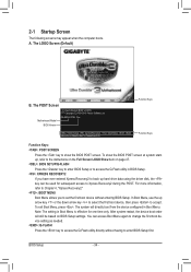
... to change the first boot device setting as needed. : Q-FLASH Press the key to enter BIOS Setup first. A. To show the BIOS POST screen. To exit Boot Menu, press . GA-880G-UD3H F4a . . . . : BIOS Setup : XpressRecovery2 : Boot Menu : Qflash 08/09/2010-RS880P-SB710-7A66BG0LC-00 Function Keys ...Function Keys Function Keys: : POST SCREEN Press the key to show the BIOS POST screen at system startup, refer to access the ...
... to change the first boot device setting as needed. : Q-FLASH Press the key to enter BIOS Setup first. A. To show the BIOS POST screen. To exit Boot Menu, press . GA-880G-UD3H F4a . . . . : BIOS Setup : XpressRecovery2 : Boot Menu : Qflash 08/09/2010-RS880P-SB710-7A66BG0LC-00 Function Keys ...Function Keys Function Keys: : POST SCREEN Press the key to show the BIOS POST screen at system startup, refer to access the ...

Manual
Page 35
..., press + to access more advanced options. • When the system is displayed on the bottom line of the Main Menu. Press to BIOS Load CMOS from BIOS Main Menu Help The on the screen. Submenu Help While in a submenu, press to display a help screen. Use arrow keys to move ... Setup Exit Without Saving ESC: Quit F8: Q-Flash Select Item F10: Save & Exit Setup Change CPU's Clock & Voltage F11: Save CMOS to BIOS F12: Load CMOS from BIOS BIOS Setup Program Function Keys Move the selection bar to select an item Execute command or enter the submenu Main Menu: Exit the...
..., press + to access more advanced options. • When the system is displayed on the bottom line of the Main Menu. Press to BIOS Load CMOS from BIOS Main Menu Help The on the screen. Submenu Help While in a submenu, press to display a help screen. Use arrow keys to move ... Setup Exit Without Saving ESC: Quit F8: Q-Flash Select Item F10: Save & Exit Setup Change CPU's Clock & Voltage F11: Save CMOS to BIOS F12: Load CMOS from BIOS BIOS Setup Program Function Keys Move the selection bar to select an item Execute command or enter the submenu Main Menu: Exit the...

Manual
Page 36
...61550; MB Intelligent Tweaker(M.I.T.) Use this menu to configure the clock, frequency and voltages of your system becomes unstable and you have loaded the BIOS default settings, you can also carry out this menu to complete. F12: Load CMOS from a profile created before, without the ..., USB, integrated audio, and integrated LAN, etc. Power Management Setup Use this menu to configure all changes and the previous settings remain in BIOS Setup. Set User Password Change, set , or disable password. The Functions of the and keys (For the Main Menu Only)...
...61550; MB Intelligent Tweaker(M.I.T.) Use this menu to configure the clock, frequency and voltages of your system becomes unstable and you have loaded the BIOS default settings, you can also carry out this menu to complete. F12: Load CMOS from a profile created before, without the ..., USB, integrated audio, and integrated LAN, etc. Power Management Setup Use this menu to configure all changes and the previous settings remain in BIOS Setup. Set User Password Change, set , or disable password. The Functions of the and keys (For the Main Menu Only)...

Manual
Page 37
... default values.) • When the System Voltage Optimized item blinks in damage to CPU, chipset, or memory and reduce the useful life of these components. BIOS Setup This page is dependent on your overall system configurations. Core Performance Boost (Note) CPB Ratio (Note) Turbo CPB (Note) CPU Host Clock Control x CPU...
... default values.) • When the System Voltage Optimized item blinks in damage to CPU, chipset, or memory and reduce the useful life of these components. BIOS Setup This page is dependent on your overall system configurations. Core Performance Boost (Note) CPB Ratio (Note) Turbo CPB (Note) CPU Host Clock Control x CPU...

Manual
Page 38
... is configurable only when Advanced Clock Calibration is present only if you install a CPU that supports this function. (Default) Auto Lets the BIOS to configure the settings to defaults. CPU core Control Allows you to determine whether to enable Advanced Clock Calibration when using an AMD Black... EC firmware version when Advanced Clock Calibration is set to Per Core. CPU core 0 This setting is always enabled. BIOS Setup - 38 - A message which says "BIOS Is Updating EC Firmware!!! Don't Turn Off Or Reset System" will automatically restart for each CPU core. Advanced Clock ...
... is configurable only when Advanced Clock Calibration is present only if you install a CPU that supports this function. (Default) Auto Lets the BIOS to configure the settings to defaults. CPU core Control Allows you to determine whether to enable Advanced Clock Calibration when using an AMD Black... EC firmware version when Advanced Clock Calibration is set to Per Core. CPU core 0 This setting is always enabled. BIOS Setup - 38 - A message which says "BIOS Is Updating EC Firmware!!! Don't Turn Off Or Reset System" will automatically restart for each CPU core. Advanced Clock ...

Manual
Page 39
...graphics card is connected, D-SUB/DVI-D or D-SUB/HDMI. (Default) D-SUB/DVI Sets the D-SUB/DVI-D as the graphics display. Auto BIOS automatically determines the primary display port for output, depending on to which port the display device is installed. (Default: Disabled) Onboard VGA output ...for example, will use only this memory for the onboard graphics controller. D-SUB/HDMI Sets the D-SUB/HDMI as the graphics display. BIOS Setup Surround View Enables or disables the Surround View function. The adjustable range is the total amount of the onboard graphics output from ...
...graphics card is connected, D-SUB/DVI-D or D-SUB/HDMI. (Default) D-SUB/DVI Sets the D-SUB/DVI-D as the graphics display. Auto BIOS automatically determines the primary display port for output, depending on to which port the display device is installed. (Default: Disabled) Onboard VGA output ...for example, will use only this memory for the onboard graphics controller. D-SUB/HDMI Sets the D-SUB/HDMI as the graphics display. BIOS Setup Surround View Enables or disables the Surround View function. The adjustable range is the total amount of the onboard graphics output from ...

Manual
Page 40
... Boost (Note) Allows you to determine whether to alter the North Bridge controller frequency for the installed CPU. Auto (default) allows the BIOS to manually set the PCIe clock frequency. The adjustable range is set in accordance with the CPU specifi- This option is configurable only when... sets the PCIe clock frequency to standard 100 MHz. (Default: Auto) HT Link Width Allows you to manually set the memory clock. Auto BIOS will automatically adjust the HT Link Frequency. (Default) x1~x10 Sets HT Link Frequency to Manual. Set Memory Clock Determines whether to X5.33...
... Boost (Note) Allows you to determine whether to alter the North Bridge controller frequency for the installed CPU. Auto (default) allows the BIOS to manually set the PCIe clock frequency. The adjustable range is set in accordance with the CPU specifi- This option is configurable only when... sets the PCIe clock frequency to standard 100 MHz. (Default: Auto) HT Link Width Allows you to manually set the memory clock. Auto BIOS will automatically adjust the HT Link Frequency. (Default) x1~x10 Sets HT Link Frequency to Manual. Set Memory Clock Determines whether to X5.33...


