Manual
Page 1
G1.Guerrilla LGA1366 socket motherboard for Intel® Core™ i7 processor family User's Manual Rev. 1002 12ME-G1GUERI-1002R
G1.Guerrilla LGA1366 socket motherboard for Intel® Core™ i7 processor family User's Manual Rev. 1002 12ME-G1GUERI-1002R
Manual
Page 2
Motherboard G1.Guerrilla Feb. 15, 2011 Motherboard G1.Guerrilla Feb. 15, 2011
Motherboard G1.Guerrilla Feb. 15, 2011 Motherboard G1.Guerrilla Feb. 15, 2011
Manual
Page 4
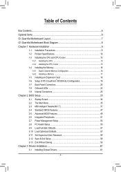
Table of Contents Box Contents...6 Optional Items...6 G1.Guerrilla Motherboard Layout 7 G1.Guerrilla Motherboard Block Diagram 8 Chapter 1 Hardware Installation 9 1-1 Installation Precautions 9 1-2 Product Specifications 10 1-3 Installing the CPU and CPU Cooler 13 1-3-1 Installing the CPU 13 1-3-2 Installing the CPU ...
Table of Contents Box Contents...6 Optional Items...6 G1.Guerrilla Motherboard Layout 7 G1.Guerrilla Motherboard Block Diagram 8 Chapter 1 Hardware Installation 9 1-1 Installation Precautions 9 1-2 Product Specifications 10 1-3 Installing the CPU and CPU Cooler 13 1-3-1 Installing the CPU 13 1-3-2 Installing the CPU ...
Manual
Page 6
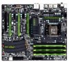
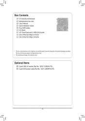
Optional Items 2-port USB 2.0 bracket (Part No. 12CR1-1UB030-5*R) 2-port SATA power cable (Part No. 12CF1-2SERPW-0*R) - 6 - The box contents are for reference only. Box Contents G1.Guerrilla motherboard Motherboard driver disk User's Manual Quick Installation Guide Four SATA cables I/O Shield 3.5" Front Panel with 2 USB 3.0/2.0 ports One 2-Way SLI bridge connector One 3-Way SLI bridge connector • The box contents above are subject to change without notice. • The motherboard image is for reference only and the actual items shall depend on the product package you obtain.
Optional Items 2-port USB 2.0 bracket (Part No. 12CR1-1UB030-5*R) 2-port SATA power cable (Part No. 12CF1-2SERPW-0*R) - 6 - The box contents are for reference only. Box Contents G1.Guerrilla motherboard Motherboard driver disk User's Manual Quick Installation Guide Four SATA cables I/O Shield 3.5" Front Panel with 2 USB 3.0/2.0 ports One 2-Way SLI bridge connector One 3-Way SLI bridge connector • The box contents above are subject to change without notice. • The motherboard image is for reference only and the actual items shall depend on the product package you obtain.
Manual
Page 7
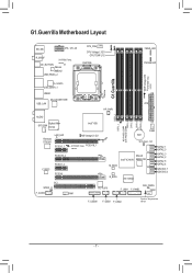
... Bigfoot Killer SYS_FAN E2100 Intel® X58 Renesas D720200 LAN_LED PCIEX1_1 NB Voltage L1/2/3 SYSTEM1 Temp. LED PHASE LED G1.Guerrilla DDR Voltage LED SYSTEM3 Temp. PCIEX16_1 sensor PCIEX16_2 CODEC PCIEX1_2 PCIEX8 PCI SPDIF_O F_AUDIO FAN1 M_BIOS B_BIOS VLI VL810 FAN3 ... SATA2_4 GSATA3_7 GSATA3_6 iTE IT8720 CLR_CMOS F_USB1 F_PANEL FAN2 F_USB30 F_USB3 F_USB2 System Temperature sensor - 7 - G1.Guerrilla Motherboard Layout KB_MS ATX_12V_2X R_SPDIF SYSTEM2 Temp. OC_BUTTON sensor JMicron JMB362 USB_ESATA_2 CPU_FAN CPU Voltage L1/2/3 CPU TEMP L1/2 LGA1366 FREQ....
... Bigfoot Killer SYS_FAN E2100 Intel® X58 Renesas D720200 LAN_LED PCIEX1_1 NB Voltage L1/2/3 SYSTEM1 Temp. LED PHASE LED G1.Guerrilla DDR Voltage LED SYSTEM3 Temp. PCIEX16_1 sensor PCIEX16_2 CODEC PCIEX1_2 PCIEX8 PCI SPDIF_O F_AUDIO FAN1 M_BIOS B_BIOS VLI VL810 FAN3 ... SATA2_4 GSATA3_7 GSATA3_6 iTE IT8720 CLR_CMOS F_USB1 F_PANEL FAN2 F_USB30 F_USB3 F_USB2 System Temperature sensor - 7 - G1.Guerrilla Motherboard Layout KB_MS ATX_12V_2X R_SPDIF SYSTEM2 Temp. OC_BUTTON sensor JMicron JMB362 USB_ESATA_2 CPU_FAN CPU Voltage L1/2/3 CPU TEMP L1/2 LGA1366 FREQ....
Manual
Page 8
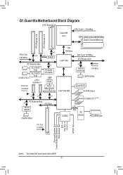
G1.Guerrilla Motherboard Block Diagram 2 PCI Express x8 CPU CLK+/- (133 MHz) LGA1366 CPU DDR3 2200/1333/1066/800 MHz Dual/3 Channel Memory 1 PCI Express x16 1 PCI ...
G1.Guerrilla Motherboard Block Diagram 2 PCI Express x8 CPU CLK+/- (133 MHz) LGA1366 CPU DDR3 2200/1333/1066/800 MHz Dual/3 Channel Memory 1 PCI Express x16 1 PCI ...
Manual
Page 34
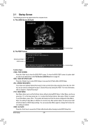
Guerrilla F1h . . . . : BIOS Setup : XpressRecovery2 : Boot Menu : Qflash 01/11/2011-X58-ICH10-7A89QG0SC-00 Function Keys Function Keys: : POST SCREEN Press the key to show ... Screen LOGO Show item on BIOS Setup settings. The system will still be used for one time only. BIOS Setup - 34 - Motherboard Model BIOS Version G1. To show the BIOS POST screen. The LOGO Screen (Default) Function Keys B. For more information, refer to Chapter 4, "Xpress Recovery2." : BOOT MENU Boot Menu allows...
Guerrilla F1h . . . . : BIOS Setup : XpressRecovery2 : Boot Menu : Qflash 01/11/2011-X58-ICH10-7A89QG0SC-00 Function Keys Function Keys: : POST SCREEN Press the key to show ... Screen LOGO Show item on BIOS Setup settings. The system will still be used for one time only. BIOS Setup - 34 - Motherboard Model BIOS Version G1. To show the BIOS POST screen. The LOGO Screen (Default) Function Keys B. For more information, refer to Chapter 4, "Xpress Recovery2." : BOOT MENU Boot Menu allows...
Manual
Page 68
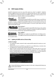
... download the latest compressed BIOS update file that support DualBIOS have two BIOS onboard, a main BIOS and a backup BIOS. G1. 4-2 BIOS Update Utilities GIGABYTE motherboards provide two unique BIOS update tools, Q-Flash™ and @BIOS™. Normally, the system works on the next ...the new BIOS file (e.g. Guerrilla F1h . . . . : BIOS Setup : XpressRecovery2 : Boot Menu : Qflash 01/11/2011-X58-ICH10-7A89QG0SC-00 Because BIOS flashing is @BIOS™? @BIOS allows you can access Q-Flash by adding one more physical BIOS chip. Unique Features - 68 - GIGABYTE Q-Flash and @BIOS ...
... download the latest compressed BIOS update file that support DualBIOS have two BIOS onboard, a main BIOS and a backup BIOS. G1. 4-2 BIOS Update Utilities GIGABYTE motherboards provide two unique BIOS update tools, Q-Flash™ and @BIOS™. Normally, the system works on the next ...the new BIOS file (e.g. Guerrilla F1h . . . . : BIOS Setup : XpressRecovery2 : Boot Menu : Qflash 01/11/2011-X58-ICH10-7A89QG0SC-00 Because BIOS flashing is @BIOS™? @BIOS allows you can access Q-Flash by adding one more physical BIOS chip. Unique Features - 68 - GIGABYTE Q-Flash and @BIOS ...

